
Model-Driven Engineering of a Railway Interlocking System
Fabio Scippacercola
1
, Roberto Pietrantuono
1
, Stefano Russo
1
, Andr
´
as Zentai
2
1
DIETI, Universit
`
a degli Studi di Napoli Federico II, Via Claudio 21, 80125 Napoli, Italy
2
Prolan Process Control Co., Szentendrei
´
ut 1-3, H-2011 Budakal
´
asz, Hungary
Keywords:
Model-Driven Design, Model-Driven Testing, Model-Driven Architecture, Safety-critical systems.
Abstract:
Model-Driven Engineering (MDE) promises to enhance system development by reducing development time,
and increasing productivity and quality. MDE is gaining popularity in several industry sectors, and is attractive
also for critical systems where they can reduce efforts and costs for verification and validation (V&V), and
can ease certification. Incorporating model-driven techniques into a legacy well-proven development cycle is
not simply a matter of placing models and transformations in the design and implementation phases.
We present the experience in the model-driven design and V&V of a safety-critical system in the railway
domain, namely the Prolan Block, a railway interlocking system manufactured by the Hungarian company
Prolan Co., required to be CENELEC SIL-4 compliant. The experience has been carried out in an industrial-
academic partnership within the EU project CECRIS. We discuss the challenges and the lessons learnt in this
pilot project of introducing MD design and testing techniques into the company’s traditional V-model process.
1 INTRODUCTION
Model-Driven Engineering (MDE) promises to en-
hance system development and testing by improv-
ing quality and increasing productivity. It has gained
popularity in some industry sectors, and is appealing
also for critical systems, where it can reduce efforts
and costs for development, verification and valida-
tion, and can provide support for product certification.
MDE is attractive due to the benefits it can pro-
vide in terms of quality of artifacts and of support for
automation. Several issues need however to be ad-
dressed in order to increase the industrial consensus
on their applicability. Many companies still consider
its adoption risky, as it requires changes in consol-
idated processes, and advanced engineering skills –
focus is on modeling, rather than on implementation.
Full comprehension of MDE risks and benefits is a
non trivial task, especially for safety-critical systems,
demanding for high levels of integrity and for certifi-
cation. More empirical studies are needed to increase
the knowledge on MDE success and failure factors
(Mohagheghi and Dehlen, 2008).
In this paper we discuss the challenges and lessons
learnt in introducing MDE for development and test-
ing in a real industrial context. Benefits and draw-
backs have been assessed in a pilot project conducted
in Prolan Control Co., a Hungarian company manu-
facturing process control and rail signaling systems.
In the industrial-academic partnership within the Eu-
ropean project “CErtification of CRItical Systems”
(CECRIS)
1
, this pilot experience aimed at introduc-
ing innovation in the development process of Prolan
Block, a safety-critical system for railway interlock-
ing that must be CENELEC EN50126, EN50128 and
EN50129 SIL-4 certified.
The proposed process, tailored to the applica-
tion domain needs, provided a complete applicable
methodology to support verification and validation in
a conventional V-Model, as suggested by CENELEC
standards. We discuss the challenges that emerged,
especially related to organizational factors and to the
degree of maturity of the supported tools. The results
provide hints about the application of model-driven
approaches, useful for companies and practitioners
that develop systems in safety-critical domains.
The rest of the paper is structured as follows. Sec-
tion 2 recalls concepts about Model-Driven Engineer-
ing, while Section 3 surveys the related work. Sec-
tion 4 describes the proposed development process;
Section 5 shows its application to the pilot project.
Section 6 discusses lessons learnt and the challenges
we faced. Section 7 concludes the papers and dis-
cusses future work.
1
website: www.cecris-project.eu
509
Scippacercola F., Pietrantuono R., Russo S. and Zentai A..
Model-Driven Engineering of a Railway Interlocking System.
DOI: 10.5220/0005244805090519
In Proceedings of the 3rd International Conference on Model-Driven Engineering and Software Development (MODELSWARD-2015), pages 509-519
ISBN: 978-989-758-083-3
Copyright
c
2015 SCITEPRESS (Science and Technology Publications, Lda.)

2 BACKGROUND
Model-Driven Engineering (MDE) refers to engineer-
ing processes and activities in which models are key
artifacts of the work (Brambilla et al., 2012). Model-
Driven Architecture (MDA) is the particular Model-
Driven Development (MDD) approach proposed by
the object standardization organization OMG (OMG,
2003).
MDE is founded on concepts of models and trans-
formations: instead of producing (textual) documents
as artifacts – requirements, design, code, test arti-
facts – in MDE engineers focus on models as pri-
mary artifacts. Models are defined in (semi-)formal
languages, that are typically machine-understandable
and drawn with the support of tools. Other artifacts
are derived through defined transformations: model-
to-model transformations (M2M), or model-to-text
transformation (M2T) from models to textual docu-
ments, source code or testing artifacts (such as test
cases and test scripts).
MDA is based on OMG standards and focuses on
software development. It introduces several abstrac-
tion levels for the separation of concerns in forward
engineering: the Computation Independent Model
(CIM), Platform Independent Model (PIM) and Plat-
form Specific Model (PSM). The CIM is at the high-
est level of abstraction; it neglects the processing and
the internal structure of the system and offers a model
that is independent from computation details. It fo-
cuses on the environment and on requirements, using
a vocabulary that is familiar to system’s domain prac-
titioners. The PIM takes into account the computation
details: it is a model that focuses on the operations
of the system, but abstracts the relations that concern
a particular technology or execution platform, such
as the hardware interface, the programming language
and the middleware. Finally, several PSMs may be
defined by refining the PIM, each one bound to spe-
cific implementation technologies and platforms. In
general, as argued by (Kent, 2002), MDE approaches
can identify different levels of decomposition and can
employ ad hoc or domain specific languages for mod-
els and transformations, whereas MDA is bound to
OMG’s standards.
MDA adopts the Unified Modeling Language
(UML), a general purpose language for software en-
gineering. The version 2.0 of UML (OMG, 2005)
introduced several improvements in the language in
order to enable UML to MDA (France et al., 2006).
One of the characteristics of UML is its capability
to be easily extended by mechanisms defined in the
standard: by UML Profiles, Tagged Values and Con-
straints, custom domain specific languages (DSLs)
can be defined, reusing and extending the elements
of the UML language.
Another OMG’s standard of interest to our work is
SysML (OMG, 2008). This modeling language par-
tially overlaps with UML 2.0, but it focuses on system
engineering, providing specific support for capturing
functional and performance requirements, quantita-
tive constraints, and information flows.
Model-Driven Testing (MDT) is a MDE activity
for V&V (Baker et al., 2007). It is not an OMG stan-
dard, but it is based on a UML standard profile, the
UML Testing Profile (UTP), which adapts UML as a
test specification language. In MDT, test infrastruc-
ture, test cases, and test scripts are derived by UTP
models through transformations.
3 RELATED WORK
There are several experience reports on the applica-
tion of MDE in complete or pilot projects. A sys-
tematic review of them can be found in (Mohagheghi
and Dehlen, 2008). MDE is generally perceived as
positive in practice, especially because it improves
the productivity, shortens the development time, in-
creases the quality of generated artifacts, and auto-
mates several activities in the development process.
However, some critical open challenges have been
also identified. For instance, in some cases the auto-
matic code generation, an important feature of MDE,
turned out to be partial, requiring the use of DSLs;
in other cases, the development processes were per-
ceived as no suited for MDE, because not thought to
exploit model-driven techniques.
Indeed, MDE lacks of well-defined processes and
it is generally introduced adapting traditional devel-
opment processes. A survey on few MDA-Based de-
velopment processes is in (Asadi and Ramsin, 2008).
In (Carrozza et al., 2012; Carrozza et al., 2013) an
adaptation is described of a V-Model process com-
pliant with MIL-STD-498 for exploiting MDA and
MDT approaches for air traffic control domain. We
build on that work for the definition of the process
presented hereafter.
The study in (Whittle et al., 2014) surveyed MDE
practices from a rather wide spread of companies.
Authors notice how MDE is not confined to a niche
market but is generally adopted everywhere. The ma-
jor part of practitioners make large use of DSLs, and
believe that benefits of MDE are not mainly in code
generation. It is interesting to note how data sug-
gest that the structure and business of an organiza-
tion have an impact on the success of MDE: model-
driven approaches seem more appropriate for compa-
MODELSWARD2015-3rdInternationalConferenceonModel-DrivenEngineeringandSoftwareDevelopment
510

nies that target specific domains than companies de-
veloping generic software. The results of the study
(Agner et al., 2013) slightly differ from the previous
mentioned survey. This one noticed a little adoption
of MDE in Brazilian companies that develop embed-
ded software. Few differences can be also found in
a preliminary survey of model-driven approaches in
Italian industry (Torchiano et al., 2011): here UML
is preferred to DSLs. This heterogeneity may be a
symptom of areas of immaturity of model-driven ap-
proaches with respect to their industrial application,
thus more investigation is required.
MDE has been applied to safety-critical systems,
for which verification and validation activities are cru-
cial and account for a large part of costs, and where
MDE is hoped to provide benefits also in view of cer-
tification. To this aim, specific challenges have to be
faced. For instance, model transformations, like au-
tomatic code generation, must be properly addressed
considering the rules of certification standards.
In the railway domain MDE has been widely ex-
perimented. Authors in (Ferrari et al., 2013) report a
successful application of Simulink/Stateflow models
for the development of an on-board equipment of an
automatic Train Protection System. By adopting par-
ticular restrictions and solutions on models, and by
using a model-based testing approach called Transla-
tion Validation, the authors were able to certify the
system according to the CENELEC standards. An-
other interesting application of MDD for the auto-
matic generation of proper configuration of computer
based interlocking systems is presented in (Svendsen
et al., 2008), in which secondary artifacts were auto-
matically generated by model transformation in order
to support CENELEC certification.
As for certification, important advantages of MD
approaches lie in the support for requirements trace-
ability and for formal methods in V&V activities.
With respect to formal methods, in (Marrone et al.,
2014), a MDE technique is proposed for the as-
sessment of railway control systems. It is based
on specialized UML profiles that enable translations
to specific formalisms, with the goal of support-
ing V&V through the automatic generation of test
cases and through model checking. Similarly, a solu-
tion for integrating model checking with various syn-
chronous dataflow languages adopted by commercial
MDD tools (MATLAB Simulink or SCADE) is dis-
cussed in the airborne domain in (Miller et al., 2010).
SCADE (Esterel Technologies, 2014) is a DO-178B
qualified model-based development environment con-
ceived specifically to address mission and safety-
critical embedded applications. A feasibility study
into the use of the SCADE suite for the verification
of railway control systems can be found in (Lawrence
and Seisenberger, 2011), while a success story of its
application in railway domain is reported in (Invensys
Rail, 2014). Other interesting approaches that focus
on how to enhance traceability and documentation ca-
pabilities of MDE to ease safety inspections and certi-
fication processes can be found in (Nejati et al., 2012;
Panesar-Walawege et al., 2011).
Despite good solutions for solving isolated prob-
lems and few examples of certification-compliant
MDE-based processes, certification is still an open
challenge for MDE. For instance, automatic code gen-
eration can even lead to an increase of efforts and
costs for certification, as reported in (Whittle et al.,
2014). Therefore, benefits and drawbacks that model-
driven techniques bring must be specifically evaluated
depending on the applications.
4 MODEL-DRIVEN APPROACH
The development process adopted in Prolan is a clas-
sic V-model (Fig. 1), whose activities can be grouped
in those concerning development (left side) and those
focusing on verification and validation (right side).
As for the left side, the development starts by
defining the system’s environment and requirements
(functional and non-functional). Then, System De-
sign and Component Design are carried out. The for-
mer defines a high level system architecture and dis-
tinguishes the parts to be realized by hardware from
those to be implemented by software. The require-
ments are then allocated to components, and new re-
quirements can be elicited in order to point out the
proper interactions among the elements. The Compo-
nent Design phase defines the internal architecture of
each component. Finally, the development side of the
‘V’ proceeds with the implementation phase.
V&V activities – at component level, integration
Validation
Design
System
Requirements
Specification
System
Design
Component
Design
Implementation
Component
Verification
Integration
Verification
Validation
Integration
Verification
Design
Component
Verification
Design
Development*
Verifica1on*and*Valida1on*
Figure 1: A V-Model process.
Model-DrivenEngineeringofaRailwayInterlockingSystem
511

level, and system level – are performed in the right
side of the V-model, preceded by the corresponding
planning activities: for instance, a validation plan is
produced as soon as system requirements are speci-
fied; the actual Validation is then performed on the
right side after Integration Verification, in order to as-
sess the product conformance to requirements.
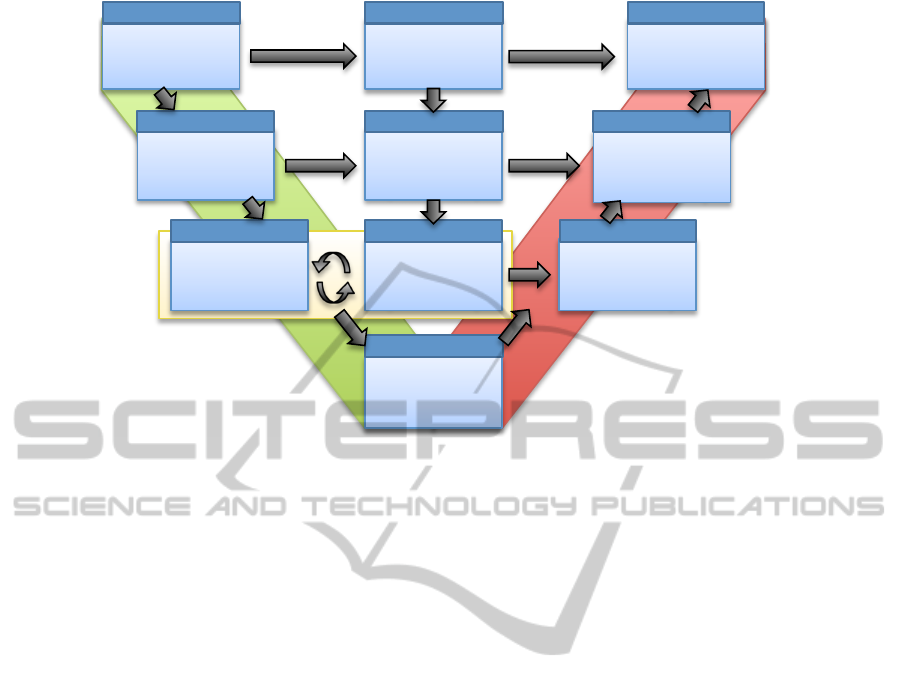
Our work is based on an adaptation of the de-
scribed V-model to introduce MDA and MDT tech-
niques (Fig. 2). On the left side of the V-model we
follow the MDA approach. At each step we focus on
one of the three viewpoints of the system (Compu-
tation Independent Viewpoint, Platform Independent
Viewpoint and Platform Specific Viewpoint), used to
define the CIM, the PIM and the PSM. The same ab-
stractions are adopted for defining the key models in
the activities of the center and right side of the ‘V’,
but both focusing on V&V activities. The methodol-
ogy allows engineers to define additional models in
order to support the V&V activities by exploiting dif-
ferent views of the system.
In System Requirements Specification, we define
a CIM for modeling the environment and the system
requirements. The CIM is defined in SysML; this
language is particularly suited in this phase, as it of-
fers requirements diagrams and allows to model both
hardware and software components.
System Design refines the CIM into a PIM, adding
computation details by defining the components and
the high level architecture of the system. The require-
ments are assigned to the elements of the system in
a way to keep them traceable. In this phase the PIM
describes, for each component, the requirements, the
interfaces, and the behavior, namely, the expected I/O
relations at components’ interfaces. UML Protocol
State Machines are suited at this stage, because they
can describe I/O relations without providing an inter-
nal description of the elements of the system.
Component Design completes the PIM with the
internal design of the elements. Considering the soft-
ware, this model is expressed in UML and should be
specific enough to be subject to simulation and model
checking. Since the Component Design focuses on
describing the dynamic behavior of the elements, it
can exploit UML Behavioral State Machines.
In the Implementation phase, the PIM is refined
into one or more PSMs, which are bound to target
platforms, adding low level details to the PIM con-
cerning implementation. For instance, a PSM adapts
the generic types of the variables with the actual ones
provided by a programming language, and binds data
and function calls to the interfaces of the middleware
and OS that have been chosen for the instantiation.
The PSM can be translated into code to provide a par-
tial or a total implementation of the system.
The Validation Design exploits the CIM to define
an environment model named Computation Indepen-
dent Test model (CIT). The CIT is unaware of com-
putation details; it models the behavior of the actors
and of the environment. System requirements are ex-
pressed as properties or conditions in the model, such
as “no collisions between trains” must occur. The CIT
is useful to validate the system against its expected
usage by external actors, and to create a simulated en-
vironment in which engineers can assess the system’s
behavior. The model also enables engineers to per-
form special kinds of assessment, like performance
testing, because CIT can generate a representative op-
erational profile for the system.
Integration Verification Design defines a model
of the expected behavior of the system’s compo-
nents, independent from their inner design. We re-
fer to it as Black Box Platform Independent Test
model (BB-PIT). This model provides static and dy-
namic views of the system’s components, and it
is mainly used to support functional testing in the
unit/integration/system verification. The static de-
scription supports the generation of the test infras-
tructure, such as stubs and drivers for unit and inte-
gration testing. The dynamic description is composed
by: (i) behavioral models, such as UML Behavioral
State Machines, defined starting by requirements as-
signed to each component in the PIM model; (ii) test
cases, which are specified by Sequence, Activity and
State Machines diagrams using the UTP profile. Be-
havioral models are useful to support the definition of
test and verification plans and for the automatic gen-
eration of test cases. A BB-PIT can model the be-
havior of one component with more state machines,
each focusing on a different subset of functionalities,
with the possibility of composing test suites by group-
ing tests derived by several state machines. In addi-
tion, a BB-PIT supports the detection of design faults
by comparing the behavior it describes with the one
defined in the PIM. In fact, the behavior of a com-
ponent is modeled differently in the PIM and in the
BB-PIT, due to the different purposes they support: a
PIM specifies how to build the system, and represents
the specification that an actual implementation must
comply with; a BB-PIT describes the expected be-
havior in a way to verify its correspondence between
requirements and implementation (e.g., by using the
BB-PIT for test case generation, the description rep-
resents the specification that test cases must comply
with). It is finally worth noting that, since BB-PIT
derives from requirements and is barely influenced by
design details, it can support validation too.
Component Verification Design refines the BB-
MODELSWARD2015-3rdInternationalConferenceonModel-DrivenEngineeringandSoftwareDevelopment
512
CIT
CIM
(SysML)
PIM
(SysML/UML)
PIM
(UML)
PSM
(UML)
White box
PST
(UML/UTP)
Black box
PST
(UML/UTP)
Validation
Model
Black box
PIT
(UML/UTP)
Grey box
PIT
(UML/UTP)
!"#$%&'()*$+&'$*$%",-$+.&
!"#$%&'()*$+&/0/&
12(%3&#$.$45"+&"6&627%.8&
Sys. Req. Spec.
&
System Design&
Component Design&
Validation Design&
Integr. Ver. Design&
Comp. Ver. Design&
Implementation&
Comp. Verif.&
Integration Verif.&
Validation&
Figure 2: The proposed model-driven V-Model. Boxes show the activities, the models produced, and the formalisms used. The
arrows represent dependency between artifacts. The Component Design has a dependency with the Component Verification
Design if it exploits the test model to early detect faults.
PIT defining a Grey Box PIT model (GB-PIT), since
it benefits from the PIM at Component Design-level,
which provides an partial internal view of the sys-
tem. The GB-PIT enables additional verification tech-
niques that can exploit structural features for assess-
ing correctness. Following this flow, engineers fo-
cus on a functional V&V modeling in the Integration
Verification Design, and then move to functional and
structural V&V modeling in this phase. Moreover,
since an executable PIM is available in this phase,
the PIT allows performing a preliminary verification
and validation of the design model, in order to detect
defects at an early stage. In addition, by exploiting
the CIT properties on the PIM, model checking tech-
niques can assess the absence of any undesired condi-
tion in operation.
The V&V activities of the right side of V-Model
refine the CIT and the PITs considering new de-
tails deriving from the target platform, from the code
implementation, and from the PSM. Therefore, the
BB-PIT and the GB-PIT, when are refined during
these activities, become the Black Box and the White
Box Platform Specific Test (respectively, BB-PST and
WB-PST). For instance, the BB-PST can exploit the
new knowledge about the target platform arithmetic
to define a new test suite; while a WB-PST can adopt
a coverage based on the complete code of the system.
Finally, testing plans, test cases, and artifacts support-
ing the V&V are derived by the PSTs through (auto-
matic) transformations.
5 PILOT PROJECT
In order to evaluate the feasibility of the proposed
MDE ‘V’ process with respect to a real industrial
context, we set up a pilot project in the company se-
lecting a subset of requirements for the Prolan Block
(PB), a safety-critical system for railway interlock-
ing that must be CENELEC EN50126, EN50128 and
EN50129 SIL-4 certified. The system is deployed
on railway segments, which are named blocks. Each
block is equipped with a PB, with sensors for de-
tecting incoming and outgoing trains, and with traf-
fic lights that control the interlocking. The PB man-
ages the block, receiving data from sensors, and prop-
erly setting the semaphores according to its internal
state. The overall distributed railway control system
consists of interacting PBs, assuring that no collision
will happen on the railway, regulating the speed of
trains by signals. Each PB interacts with the two ad-
jacent PBs (the ones in the previous and next blocks)
through a redundant network, and receives data and
commands by stations and by human operators. Since
the interlocking is dependent on the state of the next
blocks, the PBs communicate to each other in order
to update their knowledge about the state of adjacent
blocks.
In the System Requirements Specification, we
defined a CIM model by SysML using MagicDraw
(No Magic, Inc., 2014). In the CIM, we describe the
environment and a subset of requirements for the sys-
tem. We employed Use Cases, Activity Diagrams and
Model-DrivenEngineeringofaRailwayInterlockingSystem
513
MagicDraw, 1-1 /Users/nonplay/Documents/Dropbox/Prolan Work/Shared Andras_Fabio/Models/Prolan Block/ProlanTerkoz.mdzip Next is a 3-aspect signal 19-ago-2014 13.10.23
Next is a 3-aspect signal Next is a 3-aspect signal[State Machine] stm [ ]
Yellow
Green
Red
According to the direction
Dark
On-state
OFF-state
switch off
switch off
change of direction
Block is free
Block is oc c upied
Next signal is yellow
Block is oc c upied
change of direction
switch off
change of direction
switch offswitch on
switch off
change of direction
change of direction
switch off
switch on
switch on
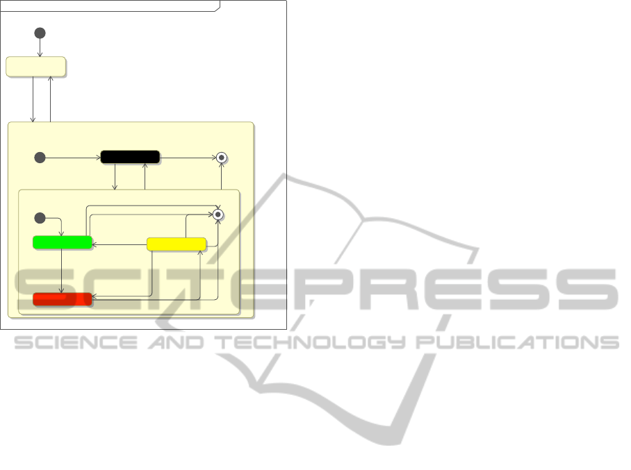
Figure 3: CIM state diagram showing the required dynamic
behavior of three lights semaphore.
Sequence Diagrams, as well as SysML Requirements
Diagrams. The first three types of diagram are used
mainly to specify functional requirements, while the
last one found to be particularly useful to describe
non-functional requirements. Moreover, the usage of
SysML Requirements Diagrams allowed us to easily
define relationships among requirements, such as the
ones of containment and refinement. We also adopted
Behavioral diagrams (State Machines, Activity
diagrams and Sequence diagrams) to describe the
expected behavior of the system at a high level.
We provided a simple description of the environ-
ment from the available information, by defining the
external entities and the data (messages and signals)
exchanged with the system in the CIM. A CIM di-
agram is shown in Fig. 3, where a State Machine is
used to represent the requirements on the aspects of
the traffic light, according to the events in the system.
In total, we modeled 41 Use Cases, and used 33 Se-
quence diagrams, 29 Activity diagrams, 6 State Ma-
chine diagrams and 6 SysML Requirement diagrams
to describe the functional and non-functional require-
ments.
In the System Design phase, we identified the main
software components: for each of them, we specified
the interfaces and requirements. In this phase, we
also elicited new requirements for components, and
added them to the system requirements specification.
The System Design model is specified by UML di-
agrams, namely by Component diagrams and Class
diagrams, again in MagicDraw. The components’ in-
terfaces are not bound to any programming language
or platform, but they are defined using generic ele-
ments, because at this stage we abstracted away from
platform-specific details.
The identified system contains five components:
the TrackOccupancyDetector, the NetworkCommuni-
cator, the ISController, the HMIController and the
ProlanBlockCoreLogic. The first four components
are introduced to mask the complexity of interacting
with hardware, and to provide high-level simple inter-
faces for the ProlanBlockCoreLogic.
The TrackOccupancyDetector receives signals by
the axle counter sensors and transforms low level sig-
nals (like axle detected) in high level events (such as
“train entered in the block” and “train has left the
block”). It also must manage device failures by noti-
fying special events in case of exceptional conditions.
The ISController works analogously; it sets the as-
pect of the semaphore, accordingly with the Prolan-
BlockCoreLogic, and copes with device failures (for
instance, the burnout of lights). The NetworkCommu-
nicator abstracts the operations to interact with the
network and the adjacent PBs, while the HMICon-
troller masks the human-machine interface. Finally,
the ProlanBlockCoreLogic implements the logic for
correctly setting the interlocking system by interact-
ing with all the other components.
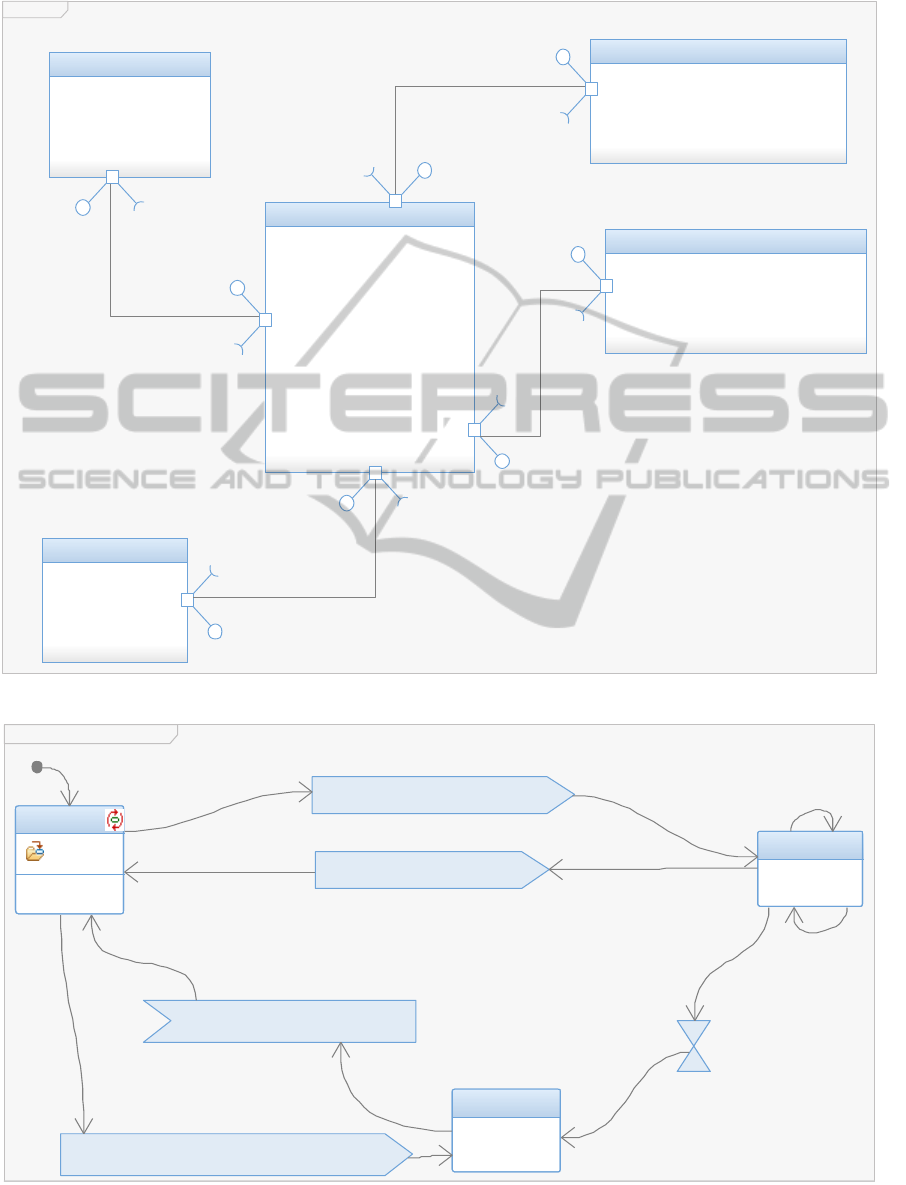
In the Component Design stage, we refine the pre-
vious model, and provide a PIM describing the low-
level design. The static view uses an UML Object
Diagram (Fig. 4), while the dynamic view consists of
UML State Machines associated with classes realiz-
ing the five components.
The PIM is defined using IBM Rhapsody Devel-
oper (hereinafter: Rhapsody) (IBM Corp., 2014b),
following guidelines to let the model be platform-
independent. For instance, to define the behavior
of exchanging messages among state machines, we
avoided inserting custom source code, but prefered
the standard UML elements of send signal action and
receive signal action. Furthermore, we adopted Rhap-
sody datatypes in lieu of target language datatypes for
the declaration of variables, because specific transla-
tion rules are defined for the former. In this way, the
system turned out to be almost entirely defined, with
only few parts to complete by specific platform code.
The PIM State Machine diagram for the Track-
OccupancyDetector is in Fig. 5: the component has
memory of axles counted by sensors at the entrance
and at the exit of the block; when the difference is not
equal to zero, a train must be in the block. Anomalous
conditions are triggered after a timeout elapsed with a
MODELSWARD2015-3rdInternationalConferenceonModel-DrivenEngineeringandSoftwareDevelopment
514
PBObjects
:Pro la nBlo c k Co re Logic
1
HMIControllerReq
IHMIControllerListener
IHMIController
IConventionalISListener
IConventionalISController
ConvISReq
ITrackOccupanyListener
ITrackOccupancyDetector
TrackOccReq
INetworkManagerListener
INetworkManager
NetworkPortReq
IHMIController
IHMIControllerListener
HMIControllerReq
ConvISReq
IConventionalISController
IConventionalISListener
ITrackOccupanyListener
ITrackOccupancyDetector
TrackOccReq
INetworkManager
NetworkPortReq
INetworkManagerListener
:Tr a c k Occ upa ncy De t e c t o r
1
ITrackOccupancyDetector
ITrackOccupanyListener
TrackOccPro
ITrackOccupancyDetector
TrackOccPro
ITrackOccupanyListener
:ISCo nt ro lle r
1
IConventionalISController
IConventionalISListener
ConvISPro
IConventionalISController
ConvISPro
IConventionalISListener
:Net wor k Com m unica to r
1
INetworkManager
INetworkManagerListener
NetworkPortPro
INetworkManager
INetworkManagerListener
NetworkPortPro
:HM ICo nt ro lle r
1
IHMIController
IHMIControllerListener
HMIControllerPro
IHMIController
IHMIControllerListener
HMIControllerPro
or
Figure 4: Object diagram representing the instances of the components of the system.
TrackOccupancyDetectorSM
ZeroSum
count = 0
NoZeroSum
axleInEvt/count = count + 1
axleOutEvt[count > 1]/count = count - 1
Failed
PBFailureEvt("TrackDetectors") to TrackOccPro
axleOutEvt/count = count - 1
trainInBlockEvt to TrackOccPro
axleInEvt/count = count + 1
trainOutBlockEvt to TrackOccPro
axleOutEvt[count == 1]/count = count - 1
TRACK_OCCUPANCY_TM
trackOccupancyDetectorResetEvt
Figure 5: The PIM diagram representing the behavior of the TrackOccupancyDetector.
Model-DrivenEngineeringofaRailwayInterlockingSystem
515

train not leaving the block, or when axle-in and axle-
out counts do not sum to zero.
We then created a PSM, as a refinement of the PIM
model, during the Implementation phase. We set sev-
eral tagged values and tool-dependent parameters to
enrich the PIM, and then used the additional infor-
mation for translating the model into code. The au-
tomatic translation of the PSM in C++ source code
generated around 7.5 thousands of lines of code. The
code is readable, understandable, and almost com-
plete. On this code, we implemented very few modi-
fications to implement the interactions with the hard-
ware that Prolan chose for deployment.
As for the central part of the ‘V’, we focused on
the Integration Verification Design and Component
Verification Design phases.
2
The PIT model should adopt useful abstractions
to support V&V and must be independent unaware
of platform specific details. In the Integration Veri-
fication Design, Prolan plans to exploit the BB-PIT
to support functional testing, by employing automatic
techniques for test cases generation. Therefore, we
composed the BB-PIT by adding a behavioral de-
scription of each component, using state machines.
These are then exploited to (automatically) generate
test cases, adopting adequacy criteria based on struc-
tural elements of the model (the full coverage of states
and transitions). Test cases are represented using
UML-UTP Sequence, Activity or State Machine dia-
grams. The graphical notation is less error-prone than
the textual format and enables to translate test cases
in multiple target testing platforms, enhancing read-
ability, reusability, and maintainability.
In this pilot project we adopted Conformiq De-
signer (Conformiq Inc., 2014) to generate automati-
cally test cases. Since Conformiq is not fully UML
compliant, we provided a behavioral description of
components in QML, a custom language required by
the tool. QML is a language based on a subset of
UML State Machines syntax with a Java-like action
language. Conformiq enables to generate tests by us-
ing an adequacy criterion based on requirements. The
tool allows defining the system requirements and trac-
ing them with respect to the behavior they specify in
the model, by means of QML annotation on transi-
tions and events. Then, test cases are automatically
generated in order to cover the elements of the model
(statements or transition) that have been annotated.
2
The definition of a detailed CIT will be subject of fu-
ture work. We are currently working on a model of train
drivers, of station’s managers and of incoming train traffic
by adopting Markov Decision Process for modeling the be-
havior of human actions, and Markov chains for modeling
operational workload and device failures.
We generated test cases for the ProlanBlockCore-
Logic, achieving the full coverage of requirements as
well as of all states and transitions. As output, Con-
formiq provided us with a sequence diagram represen-
tation of test cases (with the possibility of exporting
them in several target languages
3
, such as Java and
TTCN-3), and the traceability matrix, correlating test
cases with the features they cover.
In the Component Verification Design, the PIT
is refined with extra details deriving from the PIM.
The GB-PIT is used to generate structural test cases
to cover the elements of the design model. To this
aim, we adopted the Automatic Test Generator (ATG)
(IBM Corp., 2014a) of Rhapsody for deriving addi-
tional test cases based on structural coverage. ATG
generated ten test cases for the ProlanBlockCoreL-
ogic, as IBM-UTP Sequence Diagrams (IBM-UTP
is a custom profile available in Rhapsody). The
achieved coverage on the PIM is of 91%, with 19/21
states and 22/24 transitions being covered. We were
not able to configure properly the ATG in order to
cover the remaining two states and two transitions that
are crossed in correspondence of a time event trigger.
Therefore, we preferred to add manually one test case
to the GB-PIT in order to reach the full coverage.
Unfortunately, due to limits of the tool, we were
not able to perform simulation on the PIM at this
stage. Rhapsody cannot simulate the PIM; however,
it is able to animate the model in order to observe
the current program execution. This is a feature that
Prolan engineers found useful and easy to exploit to
get an immediate feedback on program behaviour.
More in detail, by means of the Rhapsody Panel
Diagrams, we easily created a user interface inter-
acting with the model, which allows to animate the
system execution (Fig. 6). By model animation, en-
gineers are allowed to run test cases on a preliminary
PSM, observing the effects on the model and enabling
an early detection of design faults.
To complete the picture, besides deriving test
cases from behavioral descriptions, we automati-
cally generated the testing infrastructure (such as the
drivers and stubs), by means of the Rhapsody Test-
Conductor Add On (IBM Corp., 2014c). The tool
generated around 3.5 thousands of lines of code to
provide a testing infrastructure for our system.
Finally, we moved to the right side of the ‘V’,
where PITs are refined into PSTs. At this stage, we
applied an adequacy criterion for testing based on
the source code considering the statements coverage
and the modified condition/decision (MC/DC) cover-
3
Even though Conformiq can be extended with plugins
for test scripts generation, at the time of writing we could
import test cases in Rhapsody only manually.
MODELSWARD2015-3rdInternationalConferenceonModel-DrivenEngineeringandSoftwareDevelopment
516

Panel Diagram
RED
YELLOW
GREEN
Red Light Failed
Yellow Light Failed
Green Light Failed
Push
Red Light Failure
Push
Yellow Light Failure
Push
Green Light Failure
ProlanBlock in SafeState
Axles Counted
Push
AxleIn Event
Push
AxleOut Event
Push
NextPBYellowState
Push
NextPBRedState
Push
NextPBGreenState
Figure 6: The Rhapsody Panel diagram for the PB.
age. We investigated on the support provided by the
adopted tools to this end. The ATG of Rhapsody al-
lows generating test cases to cover the source code
added manually by the user. It adopts an adequacy
criterion based on statement and on MC/DC cover-
age. However, although this first form of automation
is certainly useful, it turned out to be not satisfying in
our case, since it covered only 2/9 MC/DC test obli-
gation. This calls for better solutions to exploit the
benefits of models in these activities.
6 DISCUSSION
By completing the pilot project, we assessed the fea-
sibility, the advantages, and the drawbacks of the in-
troduced model-driven approaches in the framework
of a conventional ‘V’ model process.
The proposed process led to an improvement in
the development and testing practices. Requirements
engineers found the usage of model-driven approach
important to produce better specifications and to de-
tect more inconsistencies and missing specifications
than using the previous document-centric process.
Same feeling had the system and test designers who,
exploiting models, built quickly prototypes and test
models, and exploited the tool utilities, such as the
model animation, to cross-check their design. A gain
of productivity and quality was also recognized in
testing, because of the automatic generation of test
plans and test cases, and because of a more structured
test design process, that better exploits the interplay
between developer and tester views.
Regarding the implementation, the benefits were
not immediately evident, since the lack of a quali-
fied tool for railway standards limits the advantages
of code generation. Therefore, Prolan is still unde-
cided if the efforts for certifying automatically gener-
ated code does worth the costs for code development.
On the other hand, we recognized that MDE is fruitful
for the new capabilities that models introduce in the
overall development process, and for the better qual-
ity of produced artifacts. The automatic generation
of the code shall not be considered as a crucial fac-
tor to adopt model-driven approaches. Similar results
were observed in (Whittle et al., 2014), where code
generation was not the key factor that justified the in-
troduction of MDE.
Indeed, model-driven approaches enable engi-
neers to work on a more abstract level than the
document-centric approaches, focusing on the prob-
lem and leaving other artifacts to be derived through
transformations. Models enable to introduce new
techniques in the development, such as simulation
(model animation) and early fault detection, as well
as in V&V activities, e.g., automatic test case genera-
tion and model checking. Furthermore, requirements
between the model’s elements and the artifacts were
traced accurately, easing the generation of traceability
reports useful for certification purposes.
However, despite these advantages, the industrial
adoption of model-driven approaches presents a num-
ber of still open issues, that we experienced in our
pilot project. We proposed a general framework
for a model-driven ‘V’ process based on MDA and
MDT. Our experience shows that each activity must
Model-DrivenEngineeringofaRailwayInterlockingSystem
517

be adapted to the industrial context and to its domain-
specific needs; there is no one instantiation that can
fit all domains and applications. This is also due
to the limited support provided by tools, which can
adopt DSLs and do not provide full compatibility and
transformations with other languages. For instance,
in the activity of Integration Verification Design we
needed to use QML to automatize the generation of
test cases using Conformiq. Analogously, we noted
that Markov chain models could be suited for mod-
eling the CIT, without burdening the modelers with
more complex formalisms. Another example is pro-
vided by temporal logic formula, which could com-
plement the CIM specification to introduce particular
model checking techniques. UML 2.0 turned out to
be suited for our purposes, but it was still necessary
to exploit advanced features of the language (such as
the Connection Points in the State Machines) that are
often unknown to less experienced modelers or to en-
gineers using previous versions of UML.
Three commercial technologies have been
adopted in this study as support tools for the defined
process. We experienced little integrations between
the tools, and not full compliance with OMG’s
standards. Import and export of models among the
tools led to several problems, including the lack of
support for keeping the models consistent in the
various tools. Keeping consistency manually should
be avoided as it is error-prone. Moreover, since
the adopted tools are closed source and uncertified,
their adoption in safety-critical contexts can pose
problems, if products must undergo certification.
Therefore, we still noticed an immaturity of software
for MDE: there is a need of better integration among
tools, and more flexibility is required to support a
wider range of activities. MDE tools should not limit
the activities of engineers, but should support and
adapt to them. It is interesting to note how similar
issues were identified in (Staron, 2006) and they are
still open after about eight years.
Besides tools interoperability and integration,
other big issues to face concern skills and organiza-
tion: MDE innovation requires engineers with new
skills and strong modeling abilities, and companies
have to consider re-organizing their structure to bet-
ter fit the deep changes brought by model-driven ap-
proaches. Indeed, the management is required to
re-arrange the forces inside the company in order
to adapt consolidated practices to the transforma-
tion. The importance of developers and testers will
change, and analogously the roles assigned to require-
ments engineers and designers will become more rel-
evant. These variations impact deeply on human-
organizational factors; they translate in a severe man-
agerial issue that must be coped with in industries.
Overall, the pilot project highlighted how to in-
stantiate a model-driven ‘V’ process, able to support
a wide range of activities typical of embedded critical
systems development, favoring a clearer separation of
models used in the V&V activities. Future work will
further investigate the benefits of the proposed pro-
cess in other industrial contexts.
7 CONCLUSIONS
We presented our experience of knowledge transfer in
a company that develops safety-critical systems in the
railway domain, where we introduced model-driven
approaches by conducting a pilot project on a real in-
dustrial interlocking system that must be CENELEC
EN50126, EN50128 and EN50129 SIL-4 certified. In
this project, a V-model process modified based on
MDA and MDT was experimented: it extends the tra-
ditional process adopted by the company introducing
the MDA concepts of Computation Independent, Plat-
form Independent and Platform Specific views dur-
ing development as well as V&V activities. By ex-
ploiting the different abstractions, we showed how we
successfully supported a broad range of engineering
modeling and verification practices that enable to de-
tect faults at an early stage of development, taking ad-
vantage of automation offered by support tools.
Even if MDE is becoming a mature technology
that can provide fruitful results which are not lim-
ited to code generation, we still experienced open
challenges that must be properly addressed when in-
tegrating these approaches into existing well-proven
development processes. However, our experience is
that model-driven approaches are ready to be con-
cretely introduced in industries and they can lead to
better quality and reduced development cost in safety-
critical domains.
ACKNOWLEDGEMENTS
This research has been supported by the People
Programme (Marie Curie Actions) of the EU FP7
Programme 2007-2013 under REA grant agreement
n.324334 CECRIS (CErtification of CRItical Sys-
tems, www.cecris-project.eu).
REFERENCES
Agner, L. T. W., Soares, I. W., Stadzisz, P. C., and Sim
˜
ao,
J. M. (2013). A Brazilian Survey on UML and
MODELSWARD2015-3rdInternationalConferenceonModel-DrivenEngineeringandSoftwareDevelopment
518

Model-driven Practices for Embedded Software De-
velopment. J. Syst. Softw., 86(4):997–1005.
Asadi, M. and Ramsin, R. (2008). MDA-Based Method-
ologies: An Analytical Survey. In Schieferdecker,
I. and Hartman, A., editors, Model Driven Architec-
ture Foundations and Applications, volume 5095 of
Lecture Notes in Computer Science, pages 419–431.
Springer Berlin Heidelberg.
Baker, P., Dai, Z. R., Grabowski, J., Haugen, O., Schiefer-
decker, I., and Williams, C. (2007). Model-Driven
Testing: Using the UML Testing Profile. Springer-
Verlag New York, Inc., Secaucus, NJ, USA.
Brambilla, M., Cabot, J., and Wimmer, M. (2012). Model-
Driven Software Engineering in Practice. Morgan &
Claypool Publishers, 1
st
edition.
Carrozza, G., Faella, M., Fucci, F., Pietrantuono, R., and
Russo, S. (2012). Integrating MDT in an Industrial
Process in the Air Traffic Control Domain. In Soft-
ware Reliability Engineering Workshops (ISSREW),
2012 IEEE 23rd International Symposium on, pages
225–230.
Carrozza, G., Faella, M., Fucci, F., Pietrantuono, R., and
Russo, S. (2013). Engineering Air Traffic Control
Systems with a Model-Driven Approach. IEEE Softw.,
30(3):42–48.
Conformiq Inc. (2014). Conformiq Designer.
www.conformiq.com/products/conformiq-designer/.
Esterel Technologies (2014). SCADE Suite Product De-
scription. http://www.estereltechnolgies.com.
Ferrari, A., Fantechi, A., Magnani, G., Grasso, D., and
Tempestini, M. (2013). The Metr
ˆ
o Rio Case Study.
Sci. Comput. Program., 78(7):828–842.
France, R. B., Ghosh, S., Dinh-Trong, T., and Solberg, A.
(2006). Model-Driven Development Using UML 2.0:
Promises and Pitfalls. Computer, 39(2):59–66.
IBM Corp. (2014a). Rational Rhapsody Auto-
matic Test Generator Add On, User Guide.
http://pic.dhe.ibm.com/infocenter/rhaphlp/v7r5/ -
topic/com.ibm.rhapsody.oem.pdf.doc/pdf/ATG
User Guide.pdf.
IBM Corp. (2014b). Rational Rhapsody Devel-
oper. http://www-03.ibm.com/software/ prod-
ucts/it/ratirhap.
IBM Corp. (2014c). Rational Rhapsody TestConductor Add
On, User Guide. http://pic.dhe.ibm.com/infocenter/-
rhaphlp/v7r6/topic/com.ibm.rhp.oem.pdf.doc/pdf/-
RTC User Guide.pdf.
Invensys Rail (2014). Invensys Rail Discovers Ag-
ile Development Process with SCADE Suite.
http://www.esterel-technologies.com/success-
stories/invensys-rail/.
Kent, S. (2002). Model Driven Engineering. In Proceedings
of the Third International Conference on Integrated
Formal Methods, IFM ’02, pages 286–298, London,
UK, UK. Springer-Verlag.
Lawrence, A. and Seisenberger, M. (2011). Verification
of railway interlockings in SCADE. MRes Thesis,
Swansea University.
Marrone, S., Flammini, F., Mazzocca, N., Nardone, R., and
Vittorini, V. (2014). Towards Model-Driven V&V as-
sessment of railway control systems. International
Journal on Software Tools for Technology Transfer,
pages 1–15.
Miller, S. P., Whalen, M. W., and Cofer, D. D. (2010).
Software Model Checking Takes off. Commun. ACM,
53(2):58–64.
Mohagheghi, P. and Dehlen, V. (2008). Where Is the Proof?
- A Review of Experiences from Applying MDE in
Industry. In Proceedings of the 4th European Con-
ference on Model Driven Architecture: Foundations
and Applications, ECMDA-FA ’08, pages 432–443,
Berlin, Heidelberg. Springer-Verlag.
Nejati, S., Sabetzadeh, M., Falessi, D., Briand, L., and Coq,
T. (2012). A SysML-based approach to traceability
management and design slicing in support of safety
certification: Framework, tool support, and case stud-
ies. Information and Software Technology, 54(6):569
– 590.
No Magic, Inc. (2014). MagicDraw. http://www. no-
magic.com/products/magicdraw.html.
OMG (2003). MDA Guide. http://www.omg.org/cgi-
bin/doc?omg/03-06-01. Version 1.0.1.
OMG (2005). Unified Modeling Language (UML) Super-
structure. http://doc.omg.org/formal/2005-07-04.pdf.
Version 2.0.
OMG (2008). Systems Modeling Language (SysML).
http://www.omg.org/docs/formal/08-11-02.pdf. Ver-
sion 1.1.
Panesar-Walawege, R., Sabetzadeh, M., and Briand, L.
(2011). A Model-Driven Engineering Approach to
Support the Verification of Compliance to Safety
Standards. In Software Reliability Engineering (IS-
SRE), 2011 IEEE 22nd International Symposium on,
pages 30–39.
Staron, M. (2006). Adopting model driven software de-
velopment in industry a case study at two compa-
nies. In Nierstrasz, O., Whittle, J., Harel, D., and
Reggio, G., editors, Model Driven Engineering Lan-
guages and Systems, volume 4199 of Lecture Notes in
Computer Science, pages 57–72. Springer Berlin Hei-
delberg.
Svendsen, A., Olsen, G. K., Endresen, J., Moen, T., Carl-
son, E., Alme, K.-J., and Haugen, O. (2008). The Fu-
ture of Train Signaling. In Proceedings of the 11th In-
ternational Conference on Model Driven Engineering
Languages and Systems, MoDELS ’08, pages 128–
142, Berlin, Heidelberg. Springer-Verlag.
Torchiano, M., Tomassetti, F., Ricca, F., Tiso, A., and Reg-
gio, G. (2011). Preliminary Findings from a Survey on
the MD* State of the Practice. In Empirical Software
Engineering and Measurement (ESEM), 2011 Inter-
national Symposium on, pages 372–375.
Whittle, J., Hutchinson, J., and Rouncefield, M. (2014). The
State of Practice in Model-Driven Engineering. Soft-
ware, IEEE, 31(3):79–85.
Model-DrivenEngineeringofaRailwayInterlockingSystem
519
