
Performance Evaluation of the Clustering Based Sequence Equalizer in
Direct Detection Optical Communication Links
Kristina Georgoulakis and George-Othon Glentis
University of Peloponnese, Department of Informatics and Telecommunications, Tripoli, Greece
Keywords:
Optical Communication, Direct Detection, Electronic Equalization, Maximum Likelihood Sequence Estima-
tion, Cluster based Equalizer.
Abstract:
In this paper the performance of the Clustering Based Sequence Equalizer is investigated in the context of
Intensity Modulated Direct Detection optical communications links operating at 10Gb/s, when non-return to
zero on-off keyed and optical differential encoded phase shift keyed transmission is employed. The afore-
mentioned equalizer provides an attractive implementation of the Maximum Likelihood Sequence Estimation,
comprising of two successive steps, namely a) nonparametric estimation of the channel response using a clus-
ter based approach and b) sequence estimation using the Viterbi algorithm. The performance of the cluster
based equalizer in fiber links is investigated my means of computer simulation.
1 INTRODUCTION
The Intensity Modulated Direct Detection set up
(IM/DD) has been extensively used for 10Gb/s up
to 40Gb/s commercial optical communication links
(Stavdas, 2010). In the IM/DD systems the opti-
cal to electrical conversion is directly realized via a
nonlinear device, the photodetector, which acts as a
square-law function (Agrawal, 2012). Chromatic dis-
persion (CD) is perhaps the dominant linear impair-
ment which is liable of electronic equalization. When
a train of pulses is transmitted, excessive dispersion
can force successive pulses to overlap resulting in In-
tersymbol Interference (ISI). Electronic equalization,
applied in the receiver part, is used to mitigate ei-
ther the residual CD resulting from the incomplete
optical compensation or the accumulated CD result-
ing from uncompensated optical transmission (Singer
et al., 2008).
Equalization methods based on the Maximum
Likelihood Sequence Estimation (MLSE) have been
proposed as a powerful tool for mitigating the effect
of the ISI in wireless as well as in wireline com-
munication systems (Proakis, 2001). The MLSE ap-
proach has been successfully applied in the context
of electronic equalization of optical communication
links (Agazzi et al., 2005; Foggi et al., 2006a; Foggi
et al., 2006b; Bosco and Poggiolini, 2006; Hueda
et al., 2007; Poggiolini et al., 2008; Bosco et al.,
2009; Alfiad et al., 2009; Bosco et al., 2010; Mag-
gio et al., 2014), for IM/DD non-return to zero on-
off keyed (NRZ-OOK) and for optical differential en-
coded phase shift keyed (NRZ-DPSK) transmission
set up. The MLSE electronic equalizer has been im-
plemented using the Viterbi algorithm (VA) (Proakis,
2001). The histogram method, as well as, paramet-
ric closed form approximations of the received signal
probability density function (PDF) have been utilized
for the computation of the branch metrics associated
to the VA implementation (Agazzi et al., 2005; Hueda
et al., 2007), requiring however a huge amount of data
in order to obtain reliable results. Alternatively, the
VA branch metrics can be computed at a much lower
cost, adopting a Gaussian approximation for the per-
tinent PDFs, either directly from the received data
(Alfiad et al., 2009), or by means of channel identi-
fication using a second order Volterra model (Chung,
2010).
The Clustering Based Sequence Equalizer
(CBSE) provides an attractive alternative to the
implementation of the MLSE method (Theodor-
idis et al., 1995; Georgoulakis and Theodoridis,
1997; Georgoulakis and Theodoridis, 2000). The
implementation of the MLSE equalizer requires
the estimation of the response of the transmission
channel. According to the CBSE appoach, the
design of the equalizer is treated as a classification
task (Theodoridis and Koutroumbas, 2008), thus
freeing itself from the need of an explicit adoption
of specific models for the channel as well as for the
113
Georgoulakis K. and Glentis G..
Performance Evaluation of the Clustering Based Sequence Equalizer in Direct Detection Optical Communication Links.
DOI: 10.5220/0005342601130120
In Proceedings of the 3rd International Conference on Photonics, Optics and Laser Technology (PHOTOPTICS-2015), pages 113-120
ISBN: 978-989-758-092-5
Copyright
c
2015 SCITEPRESS (Science and Technology Publications, Lda.)

interference. The CBSE approach comprises of two
successive steps, namely a) estimation of the channel
response to the transmitted data using a cluster based
approach and b) the estimation of the transmitted
sequence using the Viterbi algorithm. The main
advantage of the cluster based approach that specific
modeling of the channel or the interference is no
longer required. Moreover, the CBSE is able to cope
with either one-dimensional (1D) or two-dimensional
(2D) formulations of the received data, providing in
the later case, the advantage of using, apart from the
Euclidean, the Mahalanobis distance. One dimen-
sional CBSE implementations of the MLSE have
been proposed in the context electronic equalization
of IM/DD optical links, either implicitly (Foggi et al.,
2006b), or explicitly (Lisnanski and Weiss, 2006;
Yang et al., 2008). The application of the 2D CBSE
approach in the case of IM/DD NRZ-OOK signaling
has been discussed in (Georgoulakis et al., 2010).
In this paper, the performance of the CBSE equal-
izers is evaluated in the context of IM/DD opti-
cal communication links, when NRZ-OOK or NRZ-
DPSK transmission is employed. The performance
of the CBSE equalizers is investigated by means of
computer simulation, both for 1D as well as for 2D
formulation of the received data. In the later case,
both the Euclidean and the Mahalanobis distance are
considered for the computation of the branch metrics
of the VA. The required Optical Signal to Noise Ratio
(OSNR) for an achieved Bit Error Rate (BER) lower
that 10
−3
is used as a performance index. Moreover,
the performance of each method in a typical metro op-
tical link that consists of short or medium long haul
optical transmission system hence comprising multi-
ple fiber spans, each of length equal to 100 Km, is
investigated in terms of the achieved BER. The com-
putational complexity of each approach is also dis-
cussed. Finally, design guidelines for the selection
of the appropriate modulation format and the elec-
tronic equalization method are drawn, based on the
overall performance of each approach, in terms of the
achieved BER and the complexity of each method.
2 MLSE AND CBSE CONCEPTS
Consider the discrete time system described by the
following equation
y(n) = c(n) + w(n) (1)
where
c(n) = f (I(n),I(n− 1),...,I(n− M+ 1)) (2)
is the noiseless channel output sequence, f(.) is the
function representing the channel action, I(n) is an
equiprobable sequence of the transmitted data taken
from a binary alphabet, i.e. I(n) ∈ {0,1}, and w(n)
is the disturbance or the noise signal. The channel
memory is represented by M while the channel length
is given by L = M + 1. The MLSE selects, among
all possible transmitted sequences, the one that mini-
mizes the cost
min
{I
n
}
∑
n
(e(n))
2
(3)
where
e(n) = y(n) − c(n) (4)
The minimization of (4) is performed efficiently using
the Viterbi algorithm (Proakis, 2001).
The implementation of the MLSE equalizer re-
quires the estimation of the channel response, c(n) in
(2), for a given input sequence I(n),I(n− 1),...,I(n−
M+ 1). This in turn requires either the a priori knowl-
edge of the channel, or the identification of the chan-
nel, usually employing a parametric model, based on
the available data set. Alternatively, the channel re-
sponse to the input sequence can be estimated using
a non parametric technique known as clustering, due
to the fact the input is taken from a finite alphabet
(binary in our case) (Georgoulakis and Theodoridis,
1997). The clustering based concept focuses on the
clusters, which the received data form. The received
data y(n) form a set of B = 2
M+1
clusters in the 1D
space. Each cluster is represented by a suitably cho-
sen representative which corresponds to an estimate
of the noiseless channel response, i.e. ˆc(n) ∈ {c
m
,m =
0,1, ...,B− 1} . The clusters are usually estimated us-
ing a training sequence, although blind cluster estima-
tion may be applied (Georgoulakis and Theodoridis,
2000). Subsequently, the transmitted sequence is es-
timated using (3), by means of the VA. The resulting
MLSE implementation is known as the 1D CBSE ap-
proach.
The number of the states of the VA, in the 1D
CBSE case, is given by S = 2
M
. The number of the
branches associated to the states of the VA coincides
to the number of clusters. Given a set of training data
{I(n),y(n)}, n = 1,2,...,N, the cluster representa-
tives are estimated by averagingthose values of the re-
ceived data that belong to a certain cluster. Let I(n) =
[I(n),I(n− 1),...,I(n− M+ 1)]
T
be a vector that car-
ries the transmitted bits upon which the output signals
y(n) are constructed. Clearly, I(n) ∈ {I
0
,I
1
,.. .I
B−1
},
where I
m
denotes the binary representation of the in-
teger m, with m = 0, 1,. .., B − 1. The cluster repre-
sentatives are computed as
c
m
=
1
N
m
∑
n
(y(n)|I(n) = I
m
) (5)
PHOTOPTICS2015-InternationalConferenceonPhotonics,OpticsandLaserTechnology
114

with N
m
denoting the cardinality of the set {I(n) =
I
m
}, n = 1,2, ...,N. During the decision mode, the
branch metrics associated to each cluster of the VA
are estimated as
V
m
= (y(n) − c
m
)
2
, m = 0,1, ... ,B− 1. (6)
The branch metrics are subsequently utilized to up-
date of the metrics associated to each state of the VA
using a compare add select unit. The detection of the
transmitted symbol
ˆ
I(n− D) is performed by means
of the trace back search unit, with D ≈ 5M represent-
ing the depth of the search (Proakis, 2001).
The 2D CBSE is formulated in a similar way; the
new input is the pair of data at consequent time in-
stances n and n− 1, Thus a received signal of a higher
dimension is constructed as
y(n) =
y(n)
y(n− 1)
. (7)
The advantages of this approach over the 1D counter-
part are a) better cluster classification, and b) the abil-
ity to cope with nonwhite interference. (Georgoulakis
and Theodoridis, 1997).
The 2D CBSE minimizes the cost function
min
{I
n
}
∑
n
e
T
(n)We(n)
(8)
where
e(n) = y(n) −
f (I(n),.. .,I(n− M + 1))
f (I(n− 1),...,I(n− M)))
(9)
is the error between the received 2D data and the cor-
responding channel response. W is an appropriately
chosen weighting matrix of dimensions equal to 2×2.
The number of the states of the 2D VA is given by
S
+
= 2
M+1
and the number of the associated branches
is given by B
+
= 2
M+2
.
Let I
+
(n) = [I(n),I(n− 1),.. .,I(n− M+ 1)I(n−
M)]
T
be a vector that carries the transmitted bits upon
which the output signal vector y(n) depends upon at
the time instant n. It holds I
+
(n) ∈ {I
0
,I
1
,.. .I
B
+
−1
},
where I
m
denotes the binary representation of the in-
teger m, with m = 0,1, ... ,B
+
. During the training
mode the cluster representatives are computed as
c
m
=
1
N
+
m
∑
y(n)|I
+
(n) = I
+
m
(10)
with N
+
m
denoting the cardinality of the set {I
+
(n) =
I
+
m
}, n = 1,2, ... ,N. The choice of W =
1 0
0 1
re-
sults to the standard Euclidean distance. In this case,
the branch metrics associated to the 2D VA are esti-
mated as
V
E
m
= (y(n) − c
m
)
T
(y(n) − c
m
) (11)
A/D
OOK CBSE
OBPF
ELPF
I(n)
^
y (n)
1
y (n)
2
y(t)
Figure 1: The NRZ-OOK receiver.
with m = 0,1,.. .,B
+
− 1. Alternatively, the weight-
ing matrix in (8) may be set equal to the inverse of
the estimated error covariance matrix corresponding
to each one 2D data cluster, i.e.,
W
m
= Σ
−1
m
, m = 0,1,.. .,B
+
− 1, (12)
where
Σ
m
= (13)
1
N
+
m
∑
(y(n) − c
m
)(y(n) − c
m
)
T
|I
+
(n) = I
+
m
.
This particular choice of the weighting matrix results
to the so called Mahalanobis metric, where the branch
metrics of the 2D VA are computed as
V
M
m
= (y(n) − c
m
)Σ
−1
m
(y(n) − c
m
)
T
. (14)
3 CBSE IN OOK SIGNALING
The schematic diagram of the NRZ-OOK receiver is
depicted in Figure 1. After optical band pass filter-
ing, the optical signal is converted to an electrical sig-
nal by means of a photodetector. The electrical signal
is subsequently passed through an electrical low pass
filter and sampled by an Analog to Digital (A/D) de-
vice. Fractionally spaced sampling is employed, as in
this case the performance of the electronic equalizers
becomes less sensitive to the sampling phase of the
receiver (Singer et al., 2008).
Let T
s
being the symbol period and let y(t) be the
electrical signal that is produced at the receiver. Let
y
1
(n) ∈ ℜ and y
2
(n) ∈ ℜ denote the received signal
sampled at time instances nT
s
and nT
s
+ T
2
/2 respec-
tively (fractionally spaced at T
s
/2 is assumed). The
receiver diversity, due to the fractionally spaced sam-
pling, is incorporated into the MLSE cost as
min
{I
n
}
"
∑
n
2
∑
i=1
(y(n) − c
i
(n))
2
!#
. (15)
Here, c
i
(n) , f
i
(I(n),I(n− 1),...,I(n− M+ 1)), i =
1,2 denote the channel response to the input sequence
I(n),I(n− 1),.. .,I(n− M+ 1).
When the 1D CBSE is considered, two set of clus-
ters c
m,1
and c
m,2
, m = 0,1,. .., B − 1, are estimated
PerformanceEvaluationoftheClusteringBasedSequenceEqualizerinDirectDetectionOpticalCommunicationLinks
115
2 3 4 5 6 7 8 9
10
1
10
2
10
3
10
4
10
5
Complexity
Channel Memory
CBSE OOK
V1
V2E
V2M
Figure 2: Computational complexity of the CBSE equal-
izer in the case of NRZ-OOK signaling, for the 1D imple-
mentation (V1), the 2D implementation using the Euclidean
metric (V2E) and for the 2D implementation using the Ma-
halanobis metric (V2M).
during the training mode using (5). Each one of them
corresponds to the fractionally spaced received sig-
nals y
1
(n) and y
2
(n). During the decision mode, the
computation of the branch metrics associated to the
1D VA are computed using (6) as
V
m
=
2
∑
i=1
(y
i
(n) − c
m,i
)
2
, m = 0,...,B− 1. (16)
In the case of the 2D CBSE, the cluster representa-
tives c
m,1
and c
m,2
, m = 0,1, ... ,B
+
− 1 are estimated
using (10). When the Euclidean metric is considered,
the branch metrics of the 2D VA are computed as
V
E
m
=
2
∑
i=1
(y
i
(n) − c
m,i
)
T
(y(n) − c
m
) (17)
with m = 0,1,.. .,B
+
− 1. In the case when the Ma-
halanobis metric is adopted, the branch metrics are
V
M
m
=
2
∑
i=1
(y
1
(n) − c
m,i
)Σ
−1
m,i
(y
i
(n) − c
m,i
)
T
. (18)
Σ
m,1
and Σ
m,2
are the covariance matrices computed
using (13) for each one of the received signals y
1
(n)
and y
2
(n).
The computational complexity of the CBSE
equalizer in the case of NRZ-OOK signaling, mea-
sured in terms of the required multiplications, is given
by C
1D
OOK
= 2
M+2
, C
2DE
OOK
= 2
M+4
and C
2DM
OOK
= 5 ×
2
M+3
, for the 1D implementation, the 2D implemen-
tation using the Euclidean metric and for the 2D im-
plementation using the Mahalanobis metric, respec-
tively. The computational complexity of the NRZ-
OOK CBSE equalizers is illustrated in Figure 2, for
various values of the assumed channel memory M.
A/D
A/D
DPSK CBSE
MZDI
ELPF
ELPF
Ts
OBPF
I(n)
^
y (n)
1,c
y (n)
1,d
y (n)
2,c
y (n)
2,d
y(t)
Constructive Branch
Destructive Branch
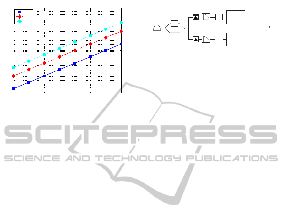
Figure 3: The NRZ-DPSK receiver.
4 CBSE IN DPSK SIGNALING
The NRZ-DPSK transmission has received increased
attention as, compared to the NRZ-OOK counterpart,
a 3dB improvement is achieved at the back-to-back
operation, (Wang and Kahn, 2004; Alfiad et al., 2009;
Bosco et al., 2010). The electronic equalization of
optical NRZ-DPSK transmission is treated in a simi-
lar way, noting however that in this case the equalizer
is designed using jointly the constructive and the de-
structive signals available at the receiver, at the output
of a pair of balanced photo-detectors used for the de-
modulation of the optical DPSK signal (Alfiad et al.,
2009). The schematic diagram of the NRZ-DPSK re-
ceiver when joint MLSE equalization is employed is
depicted in Figure 3. At the receiver side the sig-
nal is processed by a Mach-Zahnder delay interfer-
ometer which extracts the information from the op-
tical phase between two adjacent symbols, produc-
ing the constructive (upper branch) and the destruc-
tive (lower branch) output signals. These signals are
subsequently fed into two photodetectors and after
being filtered by the corresponding electrical filters
and fractionally sampled, are both used as input to
the MLSE equalizer (Alfiad et al., 2009; Bosco et al.,
2010).
As in the case of OOK signaling, fractionally
spaced sampling is considered. Thus, at each time
instant, four signals are available at the receiver. Let
y
1,c
(n) ∈ ℜ and y
2,c
(n) ∈ ℜ denote the received sig-
nals at the constructive branch of the DPSK receiver
sampled at time instances nT
s
and nT
s
+ T
2
/2. More-
over, let y
1,d
(n) ∈ ℜ and y
2,d
(n) ∈ ℜ be the corre-
sponding received signals at the destructive branch of
the DPSK receiver. The DPSK receiver diversity im-
plies the following MLSE cost
min
{I
n
}
"
∑
n
2
∑
i=1
(y
i,c
(n) − c
i,c
(n))
2
!
+
∑
n
2
∑
i=1
(y
i,d
(n) − c
i,d
(n))
2
!#
(19)
where c
1,c
(n), c
2,c
, c
1,d
and c
2,d
denote the channel re-
PHOTOPTICS2015-InternationalConferenceonPhotonics,OpticsandLaserTechnology
116

2 3 4 5 6 7 8 9
10
1
10
2
10
3
10
4
10
5
Complexity
Channel Memory
CBSE DPSK
V1
V2E
V2M
Figure 4: Computational complexity of the CBSE equal-
izer in the case of NRZ-DPSK signaling, for the 1D imple-
mentation (V1), the 2D implementation using the Euclidean
metric (V2E) and for the 2D implementation using the Ma-
halanobis metric (V2M).
sponse to the input sequence I(n),I(n− 1),.. .,I(n −
M + 1).
The 1D CBSE in the case of DPSK signaling
involves the computation of four sets of clusters,
namely the c
m,1,c
and c
m,2,c
that correspond to the
constructive branch of the receiver, as well as the
c
m,1,d
and c
m,2,d
which correspond to the destructive
branch of the receiver, m = 0, 1,. .., B, using (5) ap-
plied on the received signals y
1,c
(n), y
2,c
(n), y
1,d
(n)
and y
2,d
(n). During the decision mode, the computa-
tion of the branch metrics associated to the 1D VA, are
computed using (6), tailored to the DPSK diversity as
V =
2
∑
i=1
(y
i,c
(n) − c
m,i,c
)
2
+
2
∑
i=1
(y
i,d
(n) − c
m,i,d
)
2
.
The 2D CBSE can be derived following the approach
applied in the OOK case, noting however that the re-
ceiver diversity includes apart from the fractionally
spaced signaling, the diversity due to the constructive
and the destructive branches of the DPSK receiver.
The computational complexity of the CBSE
equalizer in the case of NRZ-DPSK signaling, is
given byC
1D
DPSK
= 2
M+3
, C
2DE
DPSK
= 2
M+5
and C
2DM
DPSK
=
5 × 2
M+4
, for the 1D implementation, the 2D im-
plementation using the Euclidean metric and for the
2D implementation using the Mahalanobis metric,
respectively. The computational complexity of the
NRZ-DPSK CBSE equalizers is illustrated in Figure
4, for various values of the assumed channel mem-
ory M. Clearly, the computational complexity of the
CBSE equalization methods in the case of DPSK sig-
naling is twice of that required in the case of OOK
signaling.
0 1 2 3 4
8
10
12
14
16
18
20
Required OSNR @ BER<10
−3
CD x 1700 ps/nm
Without Equalization
OOK
DPSK
Figure 5: Required OSNR for BER=10
−3
without elec-
tronic equalization, for OOK as well as for DPSK signaling
at 10Gb/s.
5 PERFORMANCE EVALUATION
The electronic equalization schemes are used to mit-
igate either the residual dispersion resulting from in-
complete optical compensation or the total dispersion
resulting from uncompensated optical transmission.
Here we focus on the later case, when uncompensated
optical transmission is considered. The performance
of the MLSE electronic equalizers has been investi-
gated in the past, for the IM/DD NRZ-OOK as well as
for the NRZ-DPSK signaling at 10Gb/s, using the 1D
VA method (Bosco and Poggiolini, 2006; Rosenkranz
and Xia, 2007; Chen et al., 2007; Poggiolini et al.,
2008; ?; Bosco et al., 2009). We extend the perfor-
mance analysis of the aforementioned methods, con-
sidering the 1D CBSE as well as the 2D CBSE ap-
proach described in the preceding Section. The re-
quired OSNR for an achieved BER < 10
−3
is used as
a performance index. Moreover, the performance of
each method in a typical metro optical link compris-
ing multiple fiber spans, each of length equal to 100
Km, is investigated in terms of the achieved BER.
The numerically simulated optical link operating
at 10Gb/s consists of a transmitter comprising a 1mW
CW laser at 1550 nm with an external modulator hav-
ing extinction ratio of 25 dB and a Standard Single
Mode Fiber with dispersion coefficient 17 ps/nm/km.
When NRZ-OOK transmission is considered, on the
receiver side, there is an optical filter with 20GHz
bandwidth with a 3rd order Gaussian frequency re-
sponse representing the corresponding demultiplexer
output. The photodetector is a PIN diode with a sen-
sitivity of 0.83 A/W and the receiver includes an elec-
trical filter with 4th order Bessel frequency response
with a cut-off frequency of 7GHz. The output is frac-
tionally sampled and is fed as input to the CBSE
PerformanceEvaluationoftheClusteringBasedSequenceEqualizerinDirectDetectionOpticalCommunicationLinks
117

2 4 6 8 10
8
10
12
14
16
18
20
Required OSNR @ BER<10
−3
CD x 1700 ps/nm
OOK−V1
M=2
M=3
M=4
M=5
M=6
M=7
M=8
M=9
BB
BB+3dB
(a)
2 4 6 8 10
8
10
12
14
16
18
20
Required OSNR @ BER<10
−3
CD x 1700 ps/nm
OOK−V2E
M=2
M=3
M=4
M=5
M=6
M=7
M=8
M=9
BB
BB+3dB
(b)
2 4 6 8 10
8
10
12
14
16
18
20
Required OSNR @ BER<10
−3
CD x 1700 ps/nm
OOK−V2M
M=2
M=3
M=4
M=5
M=6
M=7
M=8
M=9
BB
BB+3dB
(c)
2 4 6 8 10
8
10
12
14
16
18
20
Required OSNR @ BER<10
−3
CD x 1700 ps/nm
DPSK−V1
M=2
M=3
M=4
M=5
M=6
M=7
M=8
M=9
BB
BB+3dB
(d)
2 4 6 8 10
8
10
12
14
16
18
20
Required OSNR @ BER<10
−3
CD x 1700 ps/nm
DPSK−V2E
M=2
M=3
M=4
M=5
M=6
M=7
M=8
M=9
BB
BB+3dB
(e)
2 4 6 8 10
8
10
12
14
16
18
20
Required OSNR @ BER<10
−3
CD x 1700 ps/nm
DPSK−V2M
M=2
M=3
M=4
M=5
M=6
M=7
M=8
M=9
BB
BB+3dB
(f)
Figure 6: Required OSNR for OOK and DPSK signaling with CBSE equalization, for the the 1D implementation (V1), the
2D implementation using the Euclidean metric (V2E) and for the 2D implementation using the Mahalanobis metric (V2M),
for various sizes of the assumed channel memory M, 10Gb/s.
0 2 4 6 8 10
10
−6
10
−5
10
−4
10
−3
10
−2
10
−1
10
0
Length x 100Km
BER
OOK−V1D
M=2
M=3
M=4
M=5
M=6
M=7
M=8
M=9
FEC−LIMIT
(a)
0 2 4 6 8 10
10
−6
10
−5
10
−4
10
−3
10
−2
10
−1
10
0
Length x 100Km
BER
OOK−V2DE
M=2
M=3
M=4
M=5
M=6
M=7
M=8
M=9
FEC−LIMIT
(b)
0 2 4 6 8 10
10
−6
10
−5
10
−4
10
−3
10
−2
10
−1
10
0
Length x 100Km
BER
OOK−V2DM
M=2
M=3
M=4
M=5
M=6
M=7
M=8
M=9
FEC−LIMIT
(c)
0 2 4 6 8 10
10
−6
10
−5
10
−4
10
−3
10
−2
10
−1
10
0
Length x 100Km
BER
DPSK−V1D
M=2
M=3
M=4
M=5
M=6
M=7
M=8
M=9
FEC−LIMIT
(d)
0 2 4 6 8 10
10
−6
10
−5
10
−4
10
−3
10
−2
10
−1
10
0
Length x 100Km
BER
DPSK−V2DE
M=2
M=3
M=4
M=5
M=6
M=7
M=8
M=9
FEC−LIMIT
(e)
0 2 4 6 8 10
10
−6
10
−5
10
−4
10
−3
10
−2
10
−1
10
0
Length x 100Km
BER
DPSK−V2DM
M=2
M=3
M=4
M=5
M=6
M=7
M=8
M=9
FEC−LIMIT
(f)
Figure 7: Achieve BER for electronically equalized transmission over a typical optical communication link, comprising of
multiple spans, of length equal to L = 100Km, 10Gb/s.
equalizers. In the case of NRZ-DPSK transmission,
the DPSK modulator is implemented using a standard
Mach-Zehnder modulator. At the receiver side the
signal is processed by a Mach-Zahnder delay interfer-
ometer. These signals are subsequently fed into two
photodetectors and after being filtered by the corre-
PHOTOPTICS2015-InternationalConferenceonPhotonics,OpticsandLaserTechnology
118

Table 1: Selected signaling and CBSE approach for particu-
lar values of the target BER. Notation V1, V2E and V2M is
used to indicate the CBSE approach, i.e. the 1D implemen-
tation, the 2D implementation using the Euclidean metric
and the 2D implementation using the Mahalanobis metric,
respectively. The assumed channel length and the required
computational complexity of each method are indicated as
[M/C].
L Km BER< 10
−3
BER< 10
−5
100 OOK V1 OOK V1
[2/16] [2/16]
200 OOK V1 OOK V1
[2/16] [2/16]
300 OOK V1 OOK V1
[2/16] [3/32]
400 OOK V2E OOK V2E
[2/32] [3/64]
500 OOK V2E OOK V2E
[4/128] [4/128]
600 OOK V2E OOK V1
[4/128] [6/256]
700 OOK V2E OOK V2E
[6/256] [8/2048]
800 OOK V2E OOK V2E
[7/1024] [9/4096]
900 OOK V2E DPSK V2M
[8/2048] [7/10240]
1000 DPSK V2E DPSK V2M
[9/8192] [8/20480]
sponding electrical filters and being fractionally sam-
pled. In both cases, the system is optically amplified
using a single polarization Erbium Doped Fibre Am-
plifier such that the powerat the receiverinput is equal
to the transmitted power, which is set equal to 0dBm.
The input signal I(n) is a binary sequence of
length equal to N = 2
20
. In all cases, the given results
are obtained by averaging the output of ten indepen-
dent computer experiments. The experimental con-
ditions impose a lower bound on the estimated BER,
given by BER > 10
−6
. The required OSNR versus
the accumulated CD for uncompensated NRZ-OOK
as well as for NRZ-DPSK transmission is depicted in
Figure 5. The performance of the CBSE equalizers
is illustrated in Figure 6, where it is shown the re-
quired OSNR versus the accumulated CD for the 1D
and the 2D CBSE approaches, for various values of
the assumed channel memory, varying from M = 2
and going up to M = 9. The attained performance is
compared against the the back-to-back performance
corresponding to the OOK and to the DPSK signal-
ing. For both modulation formats, the 2D CBSE us-
ing the Mahalanobis metric demonstrates the better
performance within the margin of the 3dB penalty,
followed by the 2D CBSE using the Euclidean met-
ric. The 1D CBSE has the worst performance, noting
however that it requires the least amount of computa-
tion. In all cases, the DPSK signaling performs better
than the OOK counterpart, at the expense of an in-
crease in the complexity of the transponder circuitry
and the amount of computations required by the elec-
tronic equalization modules.
The achieved BER for each modulation format,
when the CBSE approach is used for the implemen-
tation of the MLSE, is illustrated in Figure 7, for
uncompensated optical transmission over a distance
of up to 1000 Km, with the optical link compris-
ing of multiple fiber spans, each of length equal to
100 Km. Once again, the DPSK signaling outper-
forms the OOK counterpart, however at an expense
of complexity. Subsequently, the performance of each
method in terms of the required computational com-
plexity is investigated, for two different target BER,
specificaly for BER < 10
−3
and for BER < 10
−5
. The
results are tabulated in Table 1, where the selected
method, as well as the computational complexity of
each CBSE approach is presented. In the case when
the target BER is achieved by more than one meth-
ods, that which corresponds to the minimum assumed
channel lenght M is selected.
6 CONCLUSIONS
The performance of the electronic equalization using
the CBSE approach has been investigated by means of
computer simulation, in the context of IM/DD optical
communications links operating at 10Gb/s, for NRZ-
OOK as well as for NRZ-DPSK signaling. The 1D
CBSE, as well as the 2D CBSE using the Euclidean
or the Mahalanobis distance for the computation of
the branch metrics of the VA, provide an attractive ap-
proach for the implementation of the MLSE, bypass-
ing the need of explicit estimation of the optical chan-
nel response. In principle, the electronically equal-
ized DPSK signaling outperforms the OOK counter-
part. Finally, the application of the CBSE method is
considered in a simulated typical metro optical trans-
mission link. For a given value of the target BER,
the required computational complexity is investigated
for different modulation formats and for the various
discussed CBSE approaches.
ACKNOWLEDGEMENTS
This work was funded through a grant (THALES
PROTOMI, MIS 377322) in the framework of the
O.P. Education and Lifelong Learning from Commu-
nity (ESF) and national funds.
The authors would like to thank Dr. Christos Ma-
trakidis for providing the code for the simulation of
PerformanceEvaluationoftheClusteringBasedSequenceEqualizerinDirectDetectionOpticalCommunicationLinks
119

the optical communications link.
REFERENCES
Agazzi, O., Hueda, M., Carrer, H., and Crivelli, D. (2005).
Maximum likelihood sequence estimation in disper-
sive optical channels. J. Lightwave Tech., 23(2):479–
762.
Agrawal, G. (2012). Fiber Optic Communication Systems.
Wiley.
Alfiad, M. S., Borrne, V. D., Hauske, Fand Napoli, A., and
Koonen, A. M. J. (2009). Maximum-Likelihood se-
quence estimation for optical Phase-Shift Keyed mod-
ulation formats. 27(20):4583–4594.
Bosco, G., Cano, I., Poggiolini, P., Li, L., and Chen, M.
(2010). MLSE-based DQPSK transmission in 43 Gb/s
DWDM long-haul dispersion-managed optical sys-
tems. Journal of Lightwave Technology, 28(10):1573–
1581.
Bosco, G., Fonseca, D., Klonidis, D., Poggiolini, P.,
Rosenkranz, W., Teixeira, A., Tomkos, I., and Xia, C.
(2009). Electronic channel equalization techniques.
pages 23–47.
Bosco, G. and Poggiolini, P. (2006). Long-distance effec-
tiveness of MLSE IMDD receivers. IEEE Photonics
Technology Letters, 18(9):1037–1039.
Chen, W., Buchali, F., Yi, X., Shieh, W., Evans, J. S., and
Tucker, R. S. (2007). Chromatic dspersion and PMD
mitigation at 10 Gb/s using Viterbi equalization for
DPSK and DQPSK modulation formats. Optics ex-
press, 15(9):5271–6.
Chung, W. (2010). Channel estimation methods based
on Volterra kernels for MLSD in optical communi-
cation systems. IEEE Photonics Technology Letters,
22(4):2009–2011.
Foggi, T., Colavolpe, G., Forestieri, E., and Prati, G.
(2006a). Channel estimation algorithms for MLSD
in optical communication systems. IEEE Photonics
Technology Letters, 18(19):1984–1986.
Foggi, T., Forestieri, E., Colavolpe, G., and Prati, G.
(2006b). Maximum-likelihood sequence detection
with closed-form metrics in OOK optical systems im-
paired by GVD and PMD. Journal of Lightwave Tech-
nology, 24(8):3073–3087.
Georgoulakis, K., Matrakidis, C., Glentis, G. O., and
Stavdas, A. (2010). Fractionally spaced clustering
based equalizer for optical channels. In OSA SPPCom
Conference, Karlsruhe Germany.
Georgoulakis, K. and Theodoridis, S. (1997). Efficient clus-
tering techniques for channel equalization in hostile
environments. Signal Processing, 58(2):153–164.
Georgoulakis, K. and Theodoridis, S. (2000). Blind and
semi-blind equalization using hidden markov mod-
els and clustering techniques. Signal Processing,
80(9):1795 – 1805.
Hueda, M. R., Crivelli, D. E., Carrer, H. S., and Agazzi,
O. E. (2007). Parametric estimation of IM/DD op-
tical channels using new closed-form approximations
of the signal PDF. Journal of Lightwave Technology,
25(3):957–975.
Lisnanski, R. and Weiss, A. J. (2006). Low complexity gen-
eralized EM algorithm for blind channel estimation
and data detection in optical communication systems.
Signal Processing, 86(11):3393–3403.
Maggio, G. N., Hueda, M. R., and Agazzi, O. E. (2014). Re-
duced complexity MLSD receivers for nonlinear op-
tical channels. IEEE Photonics Technology Letters,
26(4):398–401.
Poggiolini, P., Bosco, G., Benlachtar, Y., Savory, S. J.,
Bayvel, P., Killey, R. I., and Prat, J. (2008). Long-haul
10 Gbit/s linear and non-linear IMDD transmission
over uncompensated standard fiber using a SQRT-
metric MLSE receiver. Optics express, 16(17):12919–
36.
Proakis, J. G. (2001). Digital Communications. McGRaw -
Hill, 4th edition edition.
Rosenkranz, W. and Xia, C. (2007). Electrical equalization
for advanced optical communication systems. AEU -
International Journal of Electronics and Communica-
tions, 61(3):153–157.
Singer, A., Shanbag, N., and Bae, H. (2008). Electronic dis-
persion compensation. IEEE Signal Proc. Magazine,
pages 110–130.
Stavdas, A., editor (2010). Core and Metro Networks. Wi-
ley.
Theodoridis, S., Cowan, C., and See, C. (1995). Schemes
for equalization of communication channels with non-
linear impairments. IEE Proceedings on Communica-
tions, 142(3):165–171.
Theodoridis, S., and Koutroumbas, K.(2001). Pattern
Recognition . Academic Press, 4th edition.
Wang, J. and Kahn, J. (2004). Impact of cromatic and
polarization-mode dispersions on DPSK systems us-
ing interferometric demodulation and direct detection.
J. Lightwave Tech., 22(2):362–371.
Yang, C., Yang, F., and Wang, Z. (2008). Clustering based
adaptive channel estimator for optical fiber communi-
cation systems. IEEE Photonics Technology Letters,
20(20):1670 – 1672.
PHOTOPTICS2015-InternationalConferenceonPhotonics,OpticsandLaserTechnology
120
