
Model-driven Engineering in Support of Development, Test and
Maintenance of Communication Middleware
A Preliminary Industrial Case-Study
Deniz Akdur
1,2
and Vahid Garousi
3
1
ASELSAN Inc., Ankara, Turkey
2
Department of Information Systems, METU, Ankara, Turkey
3
System and Software Quality Engineering Research Group (SySoQual),
Department of Software Engineering, Atilim University, Ankara, Turkey
1 INTRODUCTION
Embedded real-time software and systems (ERTS
2
)
are widespread and can be found in many devices in
our everyday life (Ebert, 2009), e.g., in cars
(Schäuffele and Zurawka, 2005), TVs (Paulin et al.,
1997), aviation (Rushby, 2011), etc. Development
and testing of embedded software is usually more
challenging (Graaf et al., 2003; Broy, 2006)
compared to regular software systems. Many ERTS
2
are also distributed systems in which collections of
independent computers interoperate. It is crucial to
systematically design, develop and test such
distributed real-time and embedded (DRE) systems.
The scale and complexity of DRE systems
makes it infeasible to deploy them in disconnected,
standalone configurations (Gokhale et al., 2008).
Therefore, communication is the heart of all
distributed systems. The latest modern DRE systems
have numerous components in which interfaces and
middleware communication layer play crucial roles.
A communication middleware provides an
environment that enables two applications to set up a
conversation and exchange data (Krafzig et al.,
2004). Defects in those components could lead to
minor issues or even life-threatening system failures.
For example, message-communication-related faults
such as wrong message sizes exchanged between the
interfaces might be left uncovered during testing
activities. Delays in integration can create huge costs
and extra effort might be needed to verify all internal
business logic and interfaces. Furthermore, late
defect correction in live systems after deployment
for these types of software systems costs much more
compared to regular software systems due to the
close hardware interactions. Thus, it is very crucial
to verify communication interfaces between
different hardware and software modules earlier to
ensure proper interoperability. Moreover, it has been
observed in several industrial contexts that when
hardware, software modules and related
communication interfaces evolve in those systems,
synchronization of source code with other artifacts
(e.g., documentation) becomes a major challenge.
In a specific industrial context, ASELSAN Inc.,
one of Turkey's leading defense companies
(ASELSAN, 2014), all the above challenges were
regularly faced and thus, to address them, we design,
implement and evaluate a toolset in the context of
Radar & Electronic Warfare Systems (REWS)
division. In this paper, we report our progress in this
ongoing R&D project. The solution approach is
based on the Model-Driven Engineering (MDE)
which is in support of development, test and
maintenance of communication middleware. The
toolset has been developed using the Eclipse
Modeling Framework (EMF) and is titled: Model-
ComM, standing for Model-driven Communication
Middleware, which automatically generates code,
document and test driver for communication
interfaces of each component depending on the type
of protocol and the architecture of the system. This
tool is currently in use by many teams in the
company, as we report in this paper.
The approach and the case study reported in this
paper is only one component of the PhD dissertation
of the first author. The thesis' overall plan is to focus
on a comprehensive investigation of industrial and
empirical evidence of using MDE, which has a
multidisciplinary research methodology. Firstly, the
thesis plans to investigate recent modeling usage and
its adoption with describing and understanding the
industrial experience, which is based on survey and
exploratory & improving case study strategies with
interviews. Secondly, to show the positive impact of
MDE by addressing the lack of empirical results in
the industry (Frankel, 2002; Hutchinson et al.,
2014), this study uses an industrial evidence to
ensure the cost effectiveness and benefit of MDE by
11
Akdur D. and Garousi V..
Model-driven Engineering in Support of Development, Test and Maintenance of Communication Middleware - A Preliminary Industrial Case-Study.
Copyright
c
2015 SCITEPRESS (Science and Technology Publications, Lda.)
realizing technology transfer (Gorschek et al., 2006)
via Model-ComM, which is based on Action
Research (AR) (Santos and Travassos, 2009).
The remainder of this paper is organized as
follows. Section 2 discusses the motivations and
problem statement. Section 3 presents the related
work and need for the proposed approach. In Section
4, the solution is presented. Section 5 examines the
preliminary evaluation of the approach, in which the
applicability and usefulness of the approach by
applying it to prototype radar control software are
shown. Finally, Section 6 presents conclusions and
our ongoing/ future directions.
2 MOTIVATIONS AND PROBLEM
STATEMENT
2.1 Context and Problem Domain
The industrial context in which our project is carried
out focuses on developing radar software. The
REWS division has approximately about 40 active
projects as of 2014 and the expectation is to double
this number within five years. In addition to this,
developing hybrid systems, which are "systems of
systems", will become another major challenge by
combining various radars and electronic warfare
systems in a single product. All of these will result
in a major increase in complexity of software for
new products and will highlight for importance of
more systematic software engineering practices.
As a DRE system, a radar system is an object
detection system which uses electromagnetic waves
to determine the range, altitude, direction or speed of
objects such as aircrafts, ships and guided missiles
(Stimson, 1998) by requiring several basic
components, which are yet other embedded systems
(Skolnik, 2001). A radar controller software receives
inputs from a variety of sensors, such as
temperature, rotation and radiation; and sends them
to various display units.
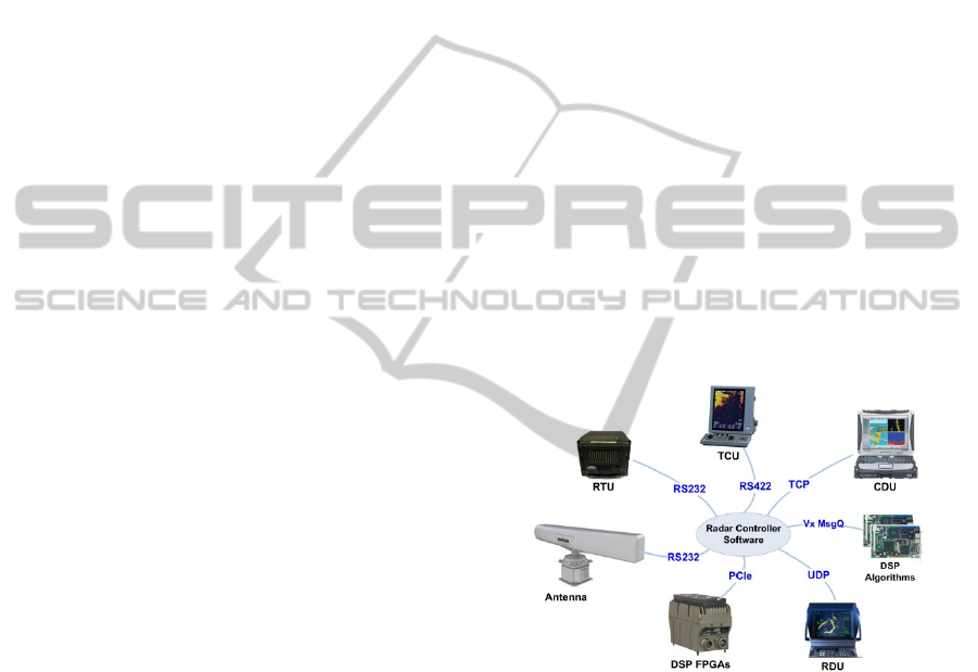
In a typical ASELSAN radar system, the
electromagnetic sub-system operate by radiating
energy into space and detecting the echoed signal
reflected from an object with the help of hardware
units such as the Receiver Transmitter Unit (RTU),
Digital Signal Processing (DSP)-based Field
Programmable Gate Array (FPGA) and antenna.
During this process, DSP algorithms are applied to
determine objects’ attributes and then the controller
software sends the location of a potential target to
the various displays like Control Display Unit
(CDU), Transceiver Compatibility Unit (TCU) or
Remote Display Unit (RDU). In this scenario, the
radar controller software usually has a large number
of both internal and external interfaces with different
units via different communication protocols such as
RS232, RS422, vxWork Message Queue (Vx
MsgQ), TCP, UDP, Peripheral Component
Interconnect Express (PCIe) to enable the system to
have close communication with other embedded
systems as shown in Figure 1.
To highlight the need for our approach to help
development of these systems, a possible message-
communication-related fault which could lead to
system failures is discussed next. A possible
scenario might occur in PCIe-based communication
protocol with FPGA, which provide support for high
sampling rate and low power consumption required
by sophisticated radars (Skolnik, 2001). However
this kind of protocol should be carefully used since it
is directly related with memory in embedded
systems (Bittner, 2012). If during message parsing,
any parameter is wrongly read, it can easily lead to
abnormalities and even a system crash, (Barry and
Crowley, 2012), which might cause even a life-
threatening situation when the radar is operating.
Figure 1: Architecture of the DRE system under study.
The above example clearly show that
verification and validation of the message interface
is important as well as fast implementation of these
communication modules for the sake of proper
interoperability. Therefore, it is obviously essential
to guarantee that these interfaces should be
compatible with each other and it is better to get all
these data from one central source. Moreover, it has
been observed that keeping source code and
documentation synchronized becomes a major
challenge. In other words, according to several
sources, e.g., (Lindvall, 2003), software maintenance
for DRE systems is challenging in general.
In summary, the real-world problem domain that
our ongoing project and this paper intend to address
MODELSWARD2015-DoctoralConsortium
12

is: the need for more systematic approaches in
development, test and maintenance of
communication middleware, as a subarea of DRE
system, in the projects under study.
2.2 Challenges and Needs
We discuss in this section the industry challenges
and needs, in further detail, that have triggered the
need for this project. For confidentiality reasons,
only non-classified information about the system
and the project will be disclosed in this paper.
In the radar controller software projects under
investigation, various types of software architecture
models have been used and various types of
interfaces were being designed, developed and
utilized by various sub-systems. During the
development process of the interfaces, the teams
have faced several major challenges which, after
systematic and extensive meetings with the
engineering teams, we grouped and summarized
them under the following four challenge areas:
- Challenge area 1: Inefficient usage of development
effort: In development of the middleware,
developers have regularly complained about
unnecessary waste of time on manually writing
communication interfaces, which include message
parsing or assembling operations. They generally
wanted to spend instead most of their time and effort
on the actual system scenarios (“business logic”). It
would have been nice to automate, as much as
possible, the “mechanical” task of writing the code
for communication interface modules by relieving
the programmer from a very error-prone task.
- Challenge area 2: Unsynchronized interface
artifacts across various software development
lifecycle (SDLC) phases: Since the projects have
various release cycles and are ongoing, it has
happened many times that a new version for a
particular artifact (e.g., interface) was released and
this update was not broadcasted to all shareholders.
Sometimes, the entire situation was becoming ad-
hoc and caused last-minute surprise and chaos, e.g.,
“It worked yesterday, but I don’t know why it
doesn’t work today; did you change anything in the
message interface?” Thus, only in runtime and
testing, such issues were surfaced which implied
major delays and rework. The synchronization-
related issue also occurred often in terms of
documentation. Whenever a typical message
interface was changed, the corresponding Interface
Control Document (ICD) was often not updated
(Parnas, 2011). In that situation, since the document
update was not synchronously done with the
implementation, they were often different.
- Challenge area 3. Insufficient unit testing of
communication interfaces before integration:
Because of the lack of simulator and test drivers,
interfaces were insufficiently tested before system
integration. There has been a need for a simulator, in
which protocols and messages can be tested under
various scenarios. Frequent stand-alone testing of a
given interface is usually considered a quick smoke
test (Kaner et al., 2001) from developers point of
view and is often considered valuable for finding
trivial defects, also for ensuring test-driven
development (TDD). Also having such a simulator
would allow developers to quickly test specific
scenarios (Myers et al., 2012).
- Challenge area 4. Inefficient team communication
and confusion of roles across different engineering
roles, e.g., system engineers, developers: Any
change request for the communication interface
among modules might come from either system
engineers or developers of inter-dependent modules.
However, there have been issues in the past on how
to properly take responsibility over ICD, which
might cause troubling situations while propagating a
change in interfaces to the all shareholders, e.g.,
quotes such as “Who is going to change ICD?”.
System Engineer in one case said: “Did you not
change ICD after new implementation? I thought
you had already changed it, but no one changed it
although three months have passed”.
2.3 Selection of the Solution Approach
Early in the project, after we identified the
challenges and needs, based on AR, the first
immediate step was to list the candidate solution
approaches from the software engineering domain
applicable to the problem and chose the solution
approach that would best fit to the context.
Due to the exponentially growing complexity of
software (Ganssle, 2008), it is agreed that the one of
the ways to manage this complexity is to use
abstraction (Kramer, 2007). Nowadays, the state-of-
the-art in software abstraction is MDE, which can be
seen as the systematic use of models as primary
artifacts during the development process
(Hutchinson et al., 2014). MDE has recently become
a hot topic in both industry and academia; there are
reports upon many years of successful experience in
the development and application of MDE (Davies et
al., 2014). It is agreed that advanced middleware
technologies by itself will not deliver the capabilities
Model-drivenEngineeringinSupportofDevelopment,TestandMaintenanceofCommunicationMiddleware-A
PreliminaryIndustrialCase-Study
13
envisioned for next-generation DRE systems and
MDE is needed not only to assist developers in
understanding their designs but also to reduce the
costs associated with trial and error by enriching
interoperability (Schantz and Schmidt, 2008). To
meet extra-functional requirements, embedded
systems development is shifting from programming
to MDE (Liggesmeyer and Trapp, 2009). We thus
decided to use MDE as our solution approach.
3 RELATED WORK AND NEED
FOR THE PROPOSED
APPROACH
After identifying the solution approach as MDE, we
conducted a literature review to see if approaches or
tools applicable to our context have been proposed
before.
The area of MDE for ERTS
2
is quite active.
There are several books, e.g., (Douglass, 2000;
Douglass, 2004; Nicolescu, 2009), and many
research articles in this area, e.g., (Pao-Ann et al.,
2001). A popular variant of MDE is the Model
Driven Architecture (MDA). The idea behind MDA
is to be able to develop and manage the whole
application life cycle by putting the focus to the
model, in which the model itself is described in a
meta-model (Moore et al., 2004). Moreover, there
are also books, which include detailed examples
from industry to illustrate real-world solutions by
presenting Model-Based Testing (MBT) from
various perspectives, which combine aspects of
ERTS
2
, e.g. (Zander et al., 2011) and also many
papers e.g. (Stefan and Bruce, 2011; Iyenghar et al.,
2011), which explore MBT in DRE systems.
Besides the technical challenges, non-
technically, since a quick response to any change
request is important for such a tool, it was necessary
in the company under study to develop it in-house
instead of adopting/buying or outsourcing.
Therefore, a customized tool, which would generate
both code and documentation from a central source,
and would guarantee module’s interoperability, was
necessary. In MDE, new tools for a specific problem
is always needed (Davies et al., 2014).
Closing the gap between software interfaces and
related artifact generation is a challenging research
problem. Our approach aims no interface errors, no
unsynchronized
software artifacts and guaranteeing
of interface integrity after implementation, which is
among the first effort to focus on MDE for error-
prone part of communication middleware.
4 SOLUTION
We have recently finished the development of our
MDE-based tool called Model-ComM to support
development, test and maintenance of
communication middleware.
Model-ComM is an Eclipse-based model-driven
tool for auto generation of code, document and test
driver for communication interfaces depending on
the type of protocol and the architecture in the
system. The inputs are specifications of the interface
messages and their parameters. We discuss the tool’s
usage overview and then its design and development
aspects next.
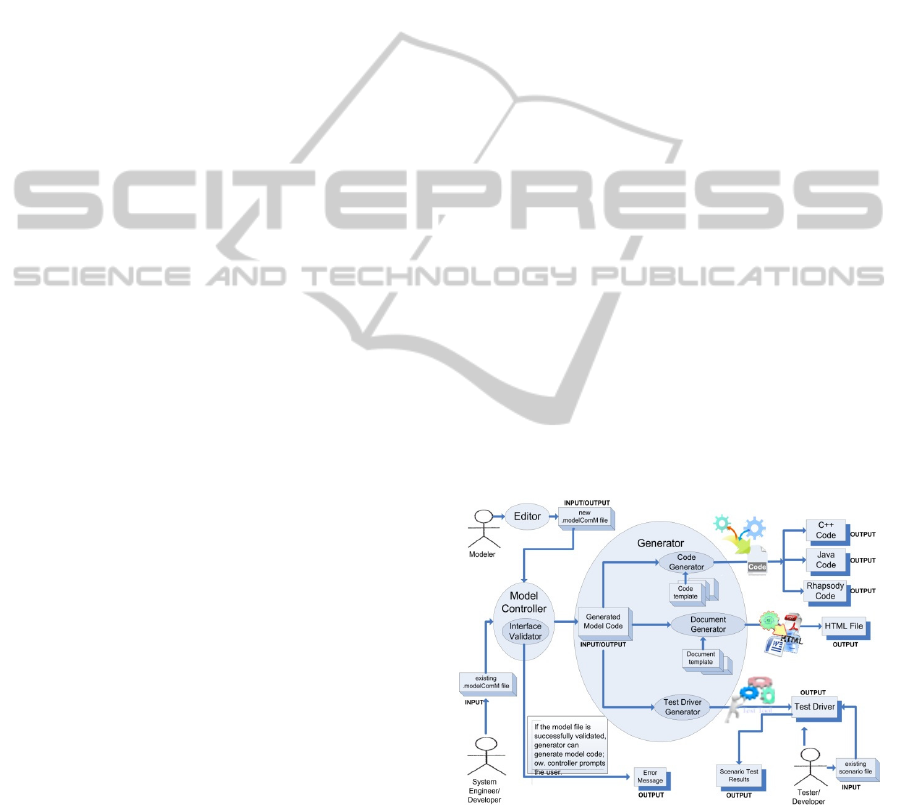
4.1 Usage Overview
The tool offers the following features:
- Code generation for communication interfaces:
The modeler can generate Java, C++ source
files and input (in SBS format) for the IBM
Rational Rhapsody tool (widely used in the
company), which is a MDE environment for
ERTS
2
(IBM, 2013).
- Document generation for all messages.
- Test driver generation for interfaces: The
engineer can use such a driver to test all
messages in a specific scenario by issuing test
inputs and expected return values.
Workflow and usage is shown in Figure 2.
Figure 2: Workflow and usage of the tool.
4.2 Design and Development Aspects
Model-ComM has been developed using EMF,
which is designed to ease the design and
implementation of structured models (Moore et al.,
2004). EMF unifies Java, XML and UML. In Figure
3, a meta-model for Model-ComM is shown.
MODELSWARD2015-DoctoralConsortium
14
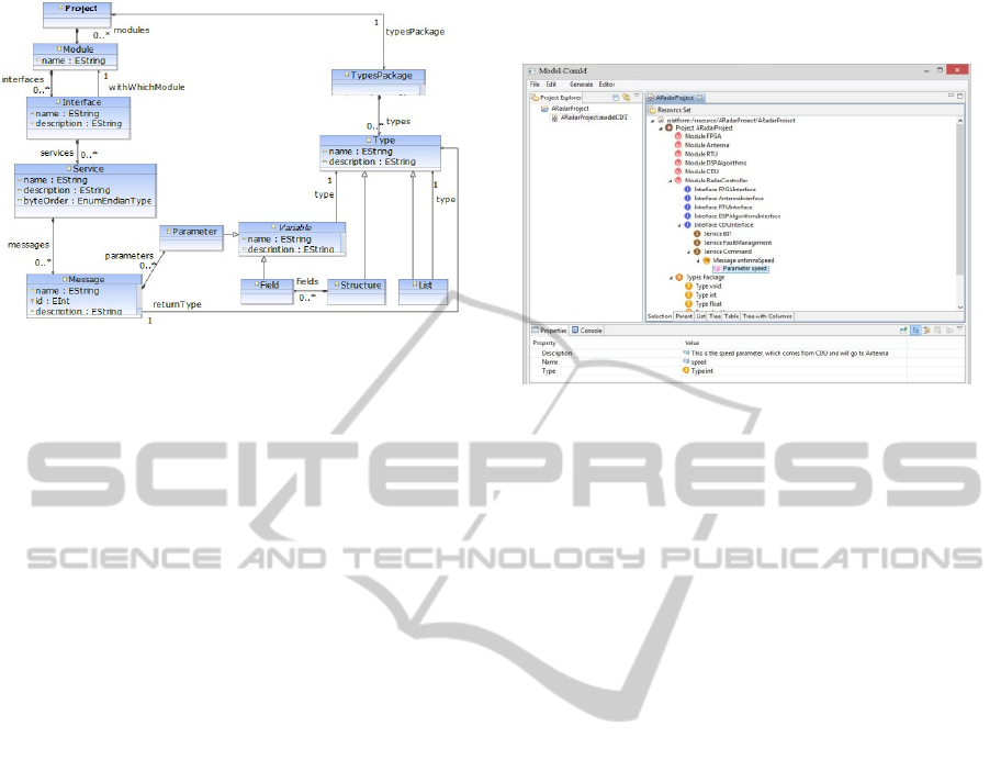
Figure 3: Meta-model of Model-ComM.
By providing the linkage between the modeling
and programming domains, EMF offers an
infrastructure to use models effectively in code. The
meta-model in Figure 3 provides model-to-model
(M2M) transformation, in which one can define any
"interface", "service", "message" and "parameter"
between any "module" in any "project" for any
communication protocol. As message parameter, one
can use "already defined types" as well as "user
defined" structure, list, etc.
The generated test driver consists of three units:
the generated communication middleware, which
provides communication interfaces with the module
tested; the test controller unit and its own UI. All
these units are generated by the tool, which might
make Model-ComM a meta-tool. When the test
driver runs, it takes all information about the module
tested from the XML file, which is generated by
meta-model. Then, by using Java Reflection
(McCluskey, 1998), the test driver finds all relations
between the generated communication middleware
and the test controller unit at run time, without
knowing the classes or methods. By this way, to ease
changeability and maintainability, the test controller
unit and UI are made independent from customized
middleware implementation.
In term of the generated documentation, the
HTML format is currently supported and it is
planned to add Word and PDF support as well. The
content is generated by the tool and to separate
appearance from content, Cascaded Style Sheet
(CSS) file format is used.
4.3 GUI and Features
Model-ComM is developed as an Eclipse Rich
Client Platform (RCP) project andit looks like the
standard Eclipse UI. It includes a menu toolbar and
three different panes: Project Explorer,
Interface/Model Definition and Properties, as shown
in Figure 4.
Figure 4: A screenshot of Model-ComM.
In the "Interface/Model Definition" pane, one
can hierarchically add all meta-model components
and save it in XML. All attribute's properties can be
editable via "Properties" pane.
In the menu tool bar, there are "File", "Edit",
"Generate" and "Editor" options. Before generating
artifacts, the model can be validated to check
whether there is a missing obligatory attribute like
missing parameter name or type, etc.
In "Generate", you have 3 submenus: Generate
Code, Generate Document and Generate Test
Driver. During generation stage, configuration
details like the module, which is wanted to generate
the code, programming language type, endian type,
destination directory etc. should be selected.
The engineer can use generated test driver to
prepare independently runnable test blocks by
sending messages with the input parameters, which
can be given via its UI. It is possible to generate test
scenarios, which can be saved and loaded later.
Comparing the incoming messages with the
expected results and presenting test results with a
colorful pass/fail status are some other features.
5 PRELIMINARY EVALUATION
IN THE INDUSTRIAL
CONTEXT
Due to confidentiality reasons, we are unable to
report the application of our tool on a real sub-
system of the case-study projects. Instead, to
demonstrate the applicability and usefulness of our
approach, we report next its evaluation on a realistic
prototype radar control software.
Model-drivenEngineeringinSupportofDevelopment,TestandMaintenanceofCommunicationMiddleware-A
PreliminaryIndustrialCase-Study
15
5.1 Usage of the Approach on a
Prototype Radar Control Software
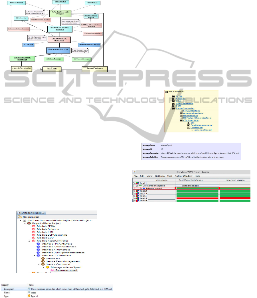
By using meta-model in Figure 3, a running example
object diagram for a radar control software is shown
in Figure 5.
Figure 5: Object Diagram.
For brevity, instead of expressing all details, the
path of bold lines is discussed. ARadarProject can
have several modules and RadarController is one of
them. This module can have several interfaces and
CDUInterface, which has TCP connection with
CDU (as mentioned in Figure 1) is one of these
interfaces. Among various services, Command has
antennaSpeed message, which has one parameter
named "speed". This parameter's type is integer and
belongs to TypesPackage. After getting this "speed"
parameter, RadarController can send it to Antenna
module by using its AntennaInterface, which has
RS232 connection (as mentioned in Figure 1).
In order to satisfy M2M transformation by EMF,
which uses this object diagram at the background
and generates code, document and test driver, it is
sufficient to model the scenario as given in Figure
6(a) and Figure 6(b).
(a): "Interface/model definition" pane
(b): "Properties" pane for "speed" parameter
Figure 6: Using Model-CDT for the prototype.
By using "Generate Code" submenu and selecting
necessary configuration, Java, C++ or IBM
Rhapsody implementation is generated.
Furthermore, by using "Generate Document"
submenu, an HTML-based ICD document, which
takes properties of all objects is generated. Figure
7(a) shows all messages within all modules by
expressing hierarchical ordering via modules,
interfaces and services at the left pane in generated
document, whereas Figure 7(b) shows the message
details when clicking on antennaSpeed message.
On the other hand, "Generate Test Driver"
submenu generates test driver. After running it, the
first screen is module selection to test. After
selecting it, all messages on that module can be
tested either manually by adding existing messages
from the upper menu or loading an existing test
scenario, which was already saved. Then, by running
all tests, the test driver UI shows pass/fail status in
colorful format as shown in Figure 7(c).
(a): Left Pane, which shows all messages
(b): Message details for "antennaSpeed" message
(c): Test driver output
Figure 7: Generated Artifacts.
5.2 Impacts, Challenges and Lessons
Learned
As discussed, MDE framework was developed to
support of embedded software development and
maintenance in the context of ASELSAN.
The usage of Model-ComM is grouped into two
categories. The first group includes the projects,
which have been using Model-ComM from the
beginning. The other group includes the projects,
which had already an existing communication
middleware technologies, decided to adopt tool. The
first group includes three projects and 10 modules;
MODELSWARD2015-DoctoralConsortium
16
whereas the second group includes one project,
whose four modules use the tool and two modules
do not. Due to confidentiality reasons, we are unable
to report the real names of these projects and
modules. As a convention, module names begin with
project names initial letter to be more
understandable. ProjectX, which is in the first group,
has three modules; whereas, ProjectY, which is in
the second group, has four modules that use the tool.
Besides presenting quantitative data in that
section, informal question & answer session results
are also presented with verbatim quotes of ProjectX
and ProjectY shareholders, which include project
managers, developers, system engineers and also
testers. All these quotes have been translated from
Turkish, as precise as possible, by the authors.
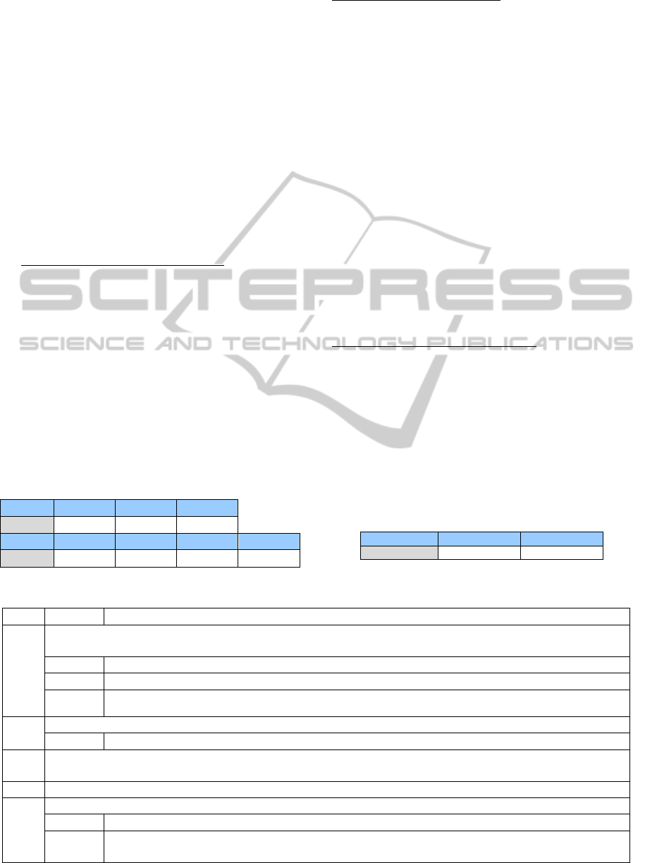
Impacts for the challenge area 1: In Table 1,
lines of code (LOC) statistics of the auto-generated
code for communication interfaces are given for
ProjectX and ProjectY. Depending on the interface
number and messages, LOC generated by Model-
ComM varies between ~3500 and ~9500. It is clear
that this saves inefficient usage of development
effort compared to before tool usage. A verbatim
quote from ProjectX manager: “As a pioneer, we
started to use Model-ComM. In our implementation
effort so far, we have gained ~15% effort savings
with code generation".
Table 1: LOC statistics of the auto-generated code for the
communication interfaces.
ProjectX ModuleX1 ModuleX2 ModuleX3
LOC ~7520 ~5500 ~4680
ProjectY ModuleY1 ModuleY2 ModuleY3 ModuleY4
LOC ~9450 ~6370 ~5240 ~3520
Impacts for Challenge area 2: ProjectX shareholders'
common idea is that with the help of automated
ICD, they can focus on more “business logic”
without worrying about synchronization of code and
documentation. Moreover, ProjectX developer says
that “Since there is only one–hand generated code
for all inter-dependent modules based on single
model, there is no last-minute surprise during
integration and we do not worry about whether
inter-dependent module’s developer changed or not
the message interface implementation”.
ProjectY manager states: “The bonus is that we
have now a reliable and one-minute-ready HTML-
based ICD; and we do not worry about the
unsynchronized artifacts”. ProjectY developer, who
has more interfaces than the other inter-dependent
modules states “I benefited more than the others not
just because of code generation but also
documentation. Because, whenever I change the
code, the document is also updated and I do not
worry about any change is not reflected in ICD.”
Impacts for the challenge area 3: Auto-generated
code also significantly affected the effort to write
simulators. Table 2 gives LOC statistics to simulate
ModuleX1’s inter-dependent modules: ModuleX2
and ModuleX3. This also saves the necessary time
for implementation of simulator. The best thing is
that, the implementation details in simulator are
generic since the generated test driver is based on
the model; not on any specific message.
Table 2: LOC statistics to implement ModuleX2’s and
ModuleX3’s simulator to test ModuleX1 in ProjectX.
ProjectX ModuleX2Sim ModuleX3Sim
LOC ~5650 ~4750
Table 3: RQs planned in our ongoing and future efforts.
RQ # Sub-RQ # RQ
1 What are quantitative benefits of the model-driven engineering approach and its associated tool-support in the case study
context?
1.1
Does using the approach reduce development, test and maintenance efforts compared to the ad-hoc baseline?
1.2
Does using the approach reduce defects across the SDLC compared to the ad-hoc baseline?
1.3
Is the approach cost effective (with respect to cost-benefit analysis and value-based software engineering (Biffl
et al., 2005))?
2 What are qualitative benefits of the model-driven engineering approach and its associated tool-support?
2.1
What types of challenges have been resolved using the approach and its tool-support?
3 How usable is the approach and how convenient is to integrate it into the SDLC lifecycle and processes in the industrial
context under study?
4 What are the further development areas of the approach and its tool-support?
5 What are the generalizability and external validity aspects of the approach?
5.1 To what extent the approach and the tools can be used in other contexts and companies?
5.2 How are out findings compare with the related work in the area of exploiting model-driven engineering in
support of software development and maintenance?
Model-drivenEngineeringinSupportofDevelopment,TestandMaintenanceofCommunicationMiddleware-A
PreliminaryIndustrialCase-Study
17

A verbatim quote from ProjectX manager:
"Moreover, to test our message interfaces; we no
longer need to wait for [completion of] their
simulators". ProjectX tester continues "With the help
of Model-ComM test driver, I do not need to
manually implement simulators; I can use my time
more efficiently. Before the tool, we implemented
simulators according to ICD and whenever anything
is changed in ICD, we had to change our simulator."
Impacts for Challenge area 4: The challenge of
taking responsibility over the ICD has started to be
resolved with auto-generation. ProjectX manager,
who had some conflicts with other shareholders on
that issue states that "it is also very helpful for non-
users of Model-ComM since they know that Model-
ComM user’s implementation is exactly what
generated HTML says. By this way, we got rid of the
document responsibility problem among
shareholders; we took this while generating code.”
6 CONCLUSIONS AND
ONGOING/FUTURE
DIRECTIONS
In the upcoming phases of our R&D project, we plan
to conduct more rigorous empirical case studies to
ensure the cost effectiveness and benefit of our
approach to the context and problem domain.
To this end, by following Goal, Question, Metric
(GQM) approach (Basili, 1994), we have already
planned a set of upcoming RQs to be studied and
addressed as shown in Table 3. The goal will be to
assess the benefits of the MDE approach and its
associated tool-support in improvement of
development and maintenance tasks in the
embedded software projects under study from the
point of view of researchers, software engineers and
managers working in the company.
REFERENCES
ASELSAN. (2014). ASELSAN. URL: www.aselsan.com.tr
[14/05/2014].
Barry, P. & Crowley, P. (2012). Embedded Platform
Architecture. In: Barry, P. & Crowley, P. (eds.)
Modern Embedded Computing. Boston: Morgan
Kaufmann.
Basili, V. C., G.; Rombach, D.H. (1994). The Goal
Question Metric Approach. Encyclopedia of Software
Engineering. Wiley.
Biffl, S., Aurum, A., Boehm, B., Erdogmus, H. &
Grünbacher, P. (2005). Value-Based Software
Engineering. Springer-Verlag New York, Inc.
Bittner, R. (2012). Speedy bus mastering PCI express. In:
22nd International Conference on Field Programmable
Logic and Applications (FPL), 523-526.
Broy, M. (2006). Challenges in automotive software
engineering. Proceedings of the 28th international
conference on Software engineering, China: ACM.
Davies, J., Gibbons, J., Welch, J. & Crichton, E. (2014).
Model-driven engineering of information systems: 10
years and 1000 versions. Science of Computer
Programming, 89, Part B, 88-104.
Douglass, B. P. (2000). Real-time UML: Developing
Efficient Objects for Embedded Systems. Addison-
Wesley.
Douglass, B. P. (2004). Real Time UML: Advances in the
UML for Real-time Systems. Addison-Wesley.
Ebert, C. J., Capers (2009). Embedded Software:
Facts, Figures, and Future. IEEE Computer Society,
42, 42-52.
Frankel, D. (2002). Model Driven Architecture: Applying
MDA to Enterprise Computing. John Wiley & Sons.
Ganssle, J. (2008). A trillion lines of code? URL:
http://www.ganssle.com/rants/atrillionlinesofcode.htm
[13/06/2014].
Gokhale, A., Balasubramanian, K., Krishna, A. S.,
Balasubramanian, J., Edwards, G., Deng, G., Turkay,
E., Parsons, J. & Schmidt, D. C. (2008). Model driven
middleware: A new paradigm for developing
distributed real-time and embedded systems. Science
of Computer Programming, 73, 39-58.
Gorschek, T., Wohlin, C., Carre, P. & Larsson, S. (2006).
A Model for Technology Transfer in Practice.
Software, IEEE, 23, 88-95.
Graaf, B., Lormans, M. & Toetenel, H. (2003). Embedded
software engineering: the state of the practice.
Software, IEEE, 20, 61-69.
Hutchinson, J., Whittle, J. & Rouncefield, M. (2014).
Model-driven engineering practices in industry:
Social, organizational and managerial factors that lead
to success or failure. Science of Computer
Programming, 89, Part B, 144-161.
Iyenghar, P., Pulvermueller, E. & Westerkamp, C. (2011).
Towards Model-Based Test automation for embedded
systems using UML and UTP. In: Emerging
Technologies & Factory Automation (ETFA), 1-9.
Kaner, C., Bach, J. & Pettichord, B. (2001). Lessons
Learned in Software Testing: A Context Driven
Approach.
New York: John Wiley & Sons Inc.
Krafzig, D., Banke, K. & Slama, D. (2004). Enterprise
SOA: Service-Oriented Architecture Best Practices
(The Coad Series). Prentice Hall PTR.
Kramer, J. (2007). Is abstraction the key to computing?
Commun. ACM, 50, 36-42.
Liggesmeyer, P. & Trapp, M. (2009). Trends in Embedded
Software Engineering. Software, IEEE, 26, 19-25.
Lindvall, M. K.-S., S.; Costa, P.; Seaman, C. (2003).
Embedded Software Maintenance. Data and Analysis
Center for Software.
MODELSWARD2015-DoctoralConsortium
18

McCluskey, G. (1998). Using Java Reflection. URL:
http://www.oracle.com/technetwork/articles/java/javar
eflection-1536171.html.
Moore, B., Dean, D., Gerber, A., Wagenknecht, G. &
Vanderheyden, P. (2004). Eclipse development using
the graphical editing framework and the eclipse
modeling framework. IBM Corp.
Myers, G. J., Sandler, C. & Badgett, T. (2012). The art of
software testing. 3rd ed. Hoboken, N.J.: John Wiley &
Sons.
Nicolescu, G. M., P. J. (2009). Model-Based Design for
Embedded Systems CRC Press.
Pao-Ann, H., Win-Bin, S., Trong-Yen, L., Jin-Ming, F. &
Sao-Jie, C. (2001). Formal verification of embedded
real-time software in component-based application
frameworks. In: Asia-Pacific Software Engineering
Conference, 71-78.
Parnas, D. (2011). Precise Documentation: The Key to
Better Software. In: Nanz, S. (ed.) The Future of
Software Engineering. Springer Berlin Heidelberg.
Paulin, P. G., Liem, C., Cornero, M., Nacabal, F. &
Goossens, G. (1997). Embedded software in real-time
signal processing systems: application and architecture
trends. Proceedings of the IEEE, 85, 419-435.
Rushby, J. (2011). New challenges in certification for
aircraft software. In: Embedded Software, 211-218.
Santos, P. S. M. d. & Travassos, G. H. (2009). Action
research use in software engineering: An initial
survey. Proceedings of the 2009 3rd International
Symposium on Empirical Software Engineering and
Measurement. IEEE Computer Society.
Schantz, R. & Schmidt, D. C. (2008). Middleware for
Distributed Systems. In: Wah, B. (ed.) Encyclopedia
of Computer Science and Engineering.
Schäuffele, J. & Zurawka, T. (2005). Automotive Software
Engineering: Principles, Processes, Methods, and
Tools. SAE International.
Skolnik, M. I. (2001). Introduction to radar systems. 3rd
ed. Boston: McGraw Hill.
Stefan, G. & Bruce, W. (2011). Model-Based Passive
Testing of Safety-Critical Components. Model-Based
Testing for Embedded Systems. CRC Press.
Stimson, G. W. (1998). Introduction to airborne radar.
2nd ed. Mendham, N.J.: SciTech Pub.
Zander, J., Schieferdecker, I. & Mosterman, P. J. (2011).
Model-Based Testing for Embedded Systems. CRC
Press.
Model-drivenEngineeringinSupportofDevelopment,TestandMaintenanceofCommunicationMiddleware-A
PreliminaryIndustrialCase-Study
19
