
A UML-based Approach for Multi-scale Software Architectures
Ilhem Khlif
1,2,3
, Mohamed Hadj Kacem
1
, Ahmed Hadj Kacem
1
and Khalil Drira
2,3
1
University of Sfax, ReDCAD Laboratory Research, Sfax, Tunisia
2
CNRS, LAAS, 7 avenue du Colonel Roche, F-31400 Toulouse, France
3
Univ. de Toulouse, LAAS, F-31400 Toulouse, France
Keywords:
Software Architecture, Multi-scale Description, UML Notation, Refinement, Abstraction, Model Transfor-
mation.
Abstract:
Multi-level software architecture design is an important issue in software engineering. Several research studies
have been done on the modeling of multi-level architectures based on UML. However, they neither included the
refinement between the levels nor clarified the relationships between them. In this paper, we propose a multi-
scale modeling approach for multi-level software architecture oriented to facilitate adaptability management.
The proposed design approach is founded on UML notations and uses component diagrams. The diagrams
are submitted to vertical and horizontal transformations for refinement; this is done to reach a fine-grain
description that contains necessary details that characterize the architectural style. The intermediate models
provide a description with a given abstraction that allow the validation to be conducted significantly while
remaining tractable w.r.t. complexity. The validation scope can involve intrinsic properties ensuring the model
correctness w.r.t. the UML specification. To achieve this, we propose a set of model refinement rules. The
rules manage the refinement and abstraction process (vertical and horizontal) as a model transformation from
a coarse-grain description to a fine-grain description. Finally, we experimented our approach by modeling an
Emergency Response and Crisis Management System (ERCMS) as a case of study.
1 INTRODUCTION
Software architecture design and description is an im-
portant activity in software engineering. It is crucial
during the earlier steps of the development of large
and complex software systems for mastering the costs
and the quality of their development.
The design of a software architecture based on
a multi-level description is a complex task. Several
studies proposed design approaches based on UML
to handle this complexity. However, they neither in-
cluded the refinement between the levels nor clarified
the relationships between them. In this work, we ex-
plore multi-level software architectures and propose
a multi-scale description for them. The multi-scale
perspective considers the refinement of a coarse-grain
description level to a fine grain description level aim-
ing to minimize software systems complexity. The
issue addressed in this approach, is to define the rela-
tionships that may exist between different description
levels of a model, and also between different horizon-
tal descriptions inside a given scale.
Our objective is to provide solutions for model-
ing software architectures to facilitate their valida-
tion at different description levels. The contribution
of this paper is a multi-scale modeling approach for
multi-level architecture oriented to facilitate adapt-
ability management. The approach extends the work
presented by Khlif et al. (Khlif et al., 2012), (Khlif
et al., 2014). In (Khlif et al., 2012), the multi-scale
modeling solution only considers a fixed number of
scales and describes a progressive process of refine-
ment from a generic model describing a given point
of view at a given scale to a specific model describ-
ing this point of view at another scale. In (Khlif
et al., 2014), we have proposed a multi-scale mod-
elling perspective for Systems of Systems (SoS) ar-
chitecture description. We have focused on SysML
(System modeling language) notations and used block
diagrams.
In this work, we extend the approach by consider-
ing both the refinement and the abstraction process as
a vertical and horizontal model transformation from
a coarse-grain description to a fine-grain description,
and by adding details on vertical and horizontal scales
until reaching a fine-grain description that contains
necessary details that characterize the architectural
style. The intermediate models provide a description
374
khlif I., Hadj Kacem M., Hadj Kacem A. and Drira K..
A UML-based Approach for Multi-scale Software Architectures.
DOI: 10.5220/0005380403740381
In Proceedings of the 17th International Conference on Enterprise Information Systems (ICEIS-2015), pages 374-381
ISBN: 978-989-758-097-0
Copyright
c
2015 SCITEPRESS (Science and Technology Publications, Lda.)

with a given abstraction that allow the validation to
be conducted significantly while remaining tractable
w.r.t. complexity. The validation scope can involve
intrinsic properties ensuring the model correctness
w.r.t. the UML specification (eg. interface compat-
ibility) To achieve this, we propose a set of model
refinement rules. The rules manage the refinement
and abstraction process (vertical and horizontal) as a
model transformation from a coarse-grain description
to a fine-grain description. In order to show the vi-
ability and usefulness of our solution, we present the
modeling of an Emergency Response and Crisis Man-
agement System (ERCMS) as a case of study.
The remainder of the paper is organized as fol-
lows. In section 2, we present a survey of related
work. We describe our approach in section 3. Section
4 illustrates the case study. We conclude and outline
some perspectives in section 5.
2 RELATED WORK
Considerable research studies have been presented on
the description of software architectures. Levels and
views are two major concepts introduced in the soft-
ware engineering domain in order to enhance the ar-
chitectural organization of complex systems’ require-
ments. A view is a description of the whole system
from the perspective of a related set of concerns. As
refinement of the architectural description continues,
the views of a software architecture can be organized
into distinct architectural levels (or layers). These lev-
els are distinguishable by their degree of abstraction
and by the stakeholder concerns they capture. The
basic idea of multi-level modeling is to explicitly rep-
resent the different abstraction levels to enable a clear
encapsulation of problems in different levels to tackle
them independently. Low level details are abstracted
for higher levels, and therefore complexity is reduced,
thus achieving a clear and coherent design. Several
works have focused on the use of UML for multi-level
modeling.
2.1 Multi-level Description with UML
Mallet et al. (Mallet et al., 2010) proposed a UML
profile called “UML Domain Specification". They ap-
plied the multi-level paradigm to the MARTE model
time.
Anwar et al. (Anwar et al., 2010) described a for-
malism and methodology to support view-based mod-
eling. They developed a design methodology based
on the UML profile, called the VUML (View-based
Unified Modeling Language), that enables the model-
ing of a software system according to the viewpoint of
each actor. The authors proposed a framework to gen-
erate a set of executable composition-oriented trans-
formations and implemented transformation rules.
Both works (Mallet et al., 2010; Anwar et al.,
2010) used UML for modeling multi-level and multi-
view architecture. They, however, did not include the
refinement between the levels or views nor clarified
the relationships that hold between them.
2.2 Architecture Refinement
In (Ferrucci et al., 1992), the authors defined the re-
finement between levels to provide more details. This
guarantees that any property of the higher level is also
verified at the lower one.
In (Rafe et al., 2009), Rafe et al. proposed an au-
tomated approach to refine models in a specific plat-
form. For each abstraction level, a style should be
designed as a graphical diagram and graph rules. In
their approach, the model design can transform or re-
fine the PIM into service specific models that are de-
signed by the rules of graph transformation. Their
modeling approach was not illustrated through a case
study or implemented in a development tool.
Juan et al. (Juan et al., 2010) proposed a formal
framework for describing software architectures us-
ing Π-ARL, an architecture refinement language that
requires the use of a toolset to support complex sys-
tems.
Bouassida et al. presented, in (Bouassida et al.,
2010), proposed a multi-level modeling approach for
collaborative systems. They examined several prob-
lems related to these systems and offered a design
framework for solving them. The authors presented
two procedures for converting models between lev-
els, namely refinement and selection. To validate
their work, the authors defined a generic algorith-
mic framework for multi-level architectural recon-
figuration and applied it to the case of group com-
munication and cooperation using formal techniques.
This work explored architectural refinement based
on graph transformations. The application of these
techniques necessesarily requires special training and
mathematical expertise.
Accordingly, several works sought to explore
other multi-level or multi-layer approaches.
2.3 Multi-level/ Multi-layer
Architecture
Lange and Middendorf (Lange and Middendorf,
2010) introduced a multi-level concept for reconfig-
AUML-basedApproachforMulti-scaleSoftwareArchitectures
375

urable architectures with more than two levels. In
their work, the authors developed an algorithm that
reduces cost and time reconfiguration and proposed a
heuristic to solve the optimal number of reconfigura-
tion levels.
In (Baresi and Guinea, 2013), Baresi et al. inves-
tigated domain-specific abstractions for a multi-level
service based system. They proposed the Multi-layer
Collection and Constraint Language(mlCCL) which
allows to analyze runtime data in a multi-layered sys-
tem. To support this language, they implemented a
visualization tool by extending their ECoWare frame-
work to event correlation. The authors did not, how-
ever, deal with the refinement between levels or lay-
ers.
Brosch et al. (Brosch et al., 2011) proposed an
approach that integrates multi-level monitoring and
adaptation of software architectures, where the au-
thors proposed a meta-model for specifying adapt-
ability characteristics in a software product line. This
model is expressed on different levels. The archi-
tectural level uses composite components to encap-
sulate subsystems and enable their replacement. The
component level selects component implementations
for a given specification. The component implemen-
tation level uses component parameters for specific
product configurations The resource level uses allo-
cation references for for product line configurations.
The authors presented a tool support that allows the
architects to design the architecture with UML mod-
els, which are automatically transformed to Markov-
based prediction models, and evaluated to determine
the expected system reliability.
2.4 Discussion
A thorough overview of the literature indicates that
several studies have been performed on the model-
ing of multi-level, multi-layer, multi-view architec-
tures. Views described the system from the perspec-
tive of the stakeholders’ concerns. As refinement of
the architectural description continues, the views of
a software architecture can be organized into distinct
architectural levels (synonym to layers). We contin-
ually update the architecture description refinement
to demonstrate that the levels can also be organized
into different description scales oriented to facilitate
the architectural organization of complex systems’ re-
quirements. Several studies have been presented for
modeling these architectures using a unified and vi-
sual notation based on UML. These semi-formal ap-
proaches did not, however, include the concept of
refinement. Although formal techniques and, more
specifically, works based on graph transformations al-
low architecture refinement, they require certain ex-
pertise in mathematics for architects. Moreover, only
few studies have provided a clearly defined process
that takes the compatibility between different descrip-
tion levels into account, a challenging condition for
the multi-level description of dynamic architectures.
Our work focuses on modeling software architectures.
Similarly to those works, we consider that a given
modeling level can be described by several scales. We
choose pure UML notations to describe multi-scale
architectures. We need to follow a clear refinement
process to transit between scales. The aim of this
work is to provide solutions for modeling software ar-
chitectures so as to facilitate their validation at differ-
ent description levels. Thus, our approach is adding
a refinement element based on “scales" compared to
other UML approaches. The multi-scale perspective
is using onely the multi-level concept to describe soft-
ware architectures.
3 PROPOSED APPROACH
We propose a multi-scale modeling approach for
multi-level software architectures. The proposed de-
sign approach is founded on UML notations and uses
component diagrams. The diagrams are submitted
to vertical and horizontal transformations for refine-
ment; this is done to reach a fine-grain description that
contains necessary details that characterize the archi-
tectural style.
We present the multi-scale approach by a two-
dimensional array describing vertical and horizontal
refinements. Vertical description levels allow the ar-
chitect to describe the same inherent requirements
while providing multiple descriptions having differ-
ent granularity levels. Under each scale, there are
several horizontal refinements. We define a Vertical
description Scale “Sv
n
" as a model that provides ad-
ditional details of design (in a vertical way) which is
related to the higher scale “Sv
n−1
" and more abstrac-
tion which is related to the lower scale “Sv
n+1
". It can
be used, for example, to represent a given description
level or a given communication layer in communicat-
ing systems. Moreover, a vertical scale can be refined
into several Horizontal description Scales “Sv
n
/Sh
m
"
providing more details of the UML initial description
(in a horizontal way). We consider that n (resp. m)
represents the scale number (n,m ≥ 0).
We start by modeling the first scale, which is de-
fined by a UML component diagram. This diagram
is refined, through model transformation operations,
until reaching the last scale that represents the ar-
chitectural style. A simple description of our pro-
ICEIS2015-17thInternationalConferenceonEnterpriseInformationSystems
376
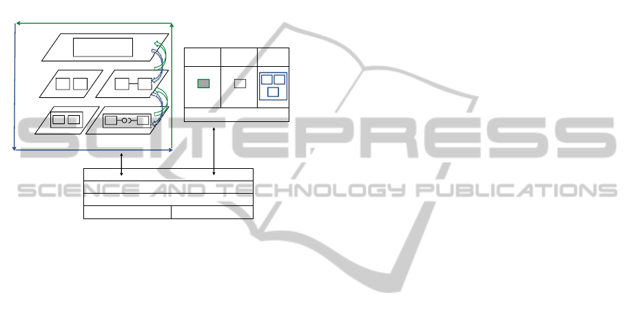
posed approach is presented in (Figure 1). We pro-
pose a hybrid approach. The top-down approach is
presented by the refinement process which transforms
architecture in both a vertical and a horizontal way.
The bottom-up approach is described by the abstrac-
tion process, which consists of vertical and horizontal
transformations. A multi-scale description guarantees
the execution of the necessary model transformations
rules. These rules manage the refinement/abstraction
between scales.
Verical
Scale 0
Vertical
Scale
1
R
E
F
I
Model transformation operations
(Refinement/abstraction)
A B S T R A C T I O N
A
B
S
T
R
A
« Require&
Delete »
« Require&
Preserve »
« Insert »
Scale
1
.
.
.
Vertical
Scale n
I
N
E
M
E
N
T
Horizontal Scale 0
Horizontal Scale m
. . .
R E F I N E M E N T
A
C
T
I
O
N
R E F I N E M E N T
Validation
Rule-oriented description technique
Model transformation rules
Refinement rules Abstraction rules
Figure 1: Description of the proposed approach.
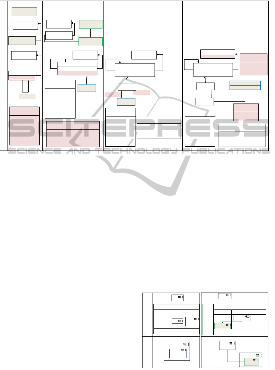
3.1 Multi-scale Description
We present the multi-scale approach by a two-
dimensional array describing vertical and horizontal
scales (Figure 2). Gray classes represent the added
details in each refined scale and white classes repre-
sent the conserved architectural properties. Vertical
scales are the vertical description levels that allow the
architect to describe the same inherent requirements
while providing multiple descriptions having differ-
ent granularity levels. Under each vertical description
scales there are several horizontal description scales.
The first scale Sv
0
begins with specifying the applica-
tion requirements. It defines the whole application by
its name.
Two horizontal refinements called horizontal
scales are associated with the first level Sv
1
. The first
horizontal scale shows all component types that com-
pose the application. The second one describes the
links between those components.
Four horizontal refinements are associated with
the second level Sv
2
. The first scale presents compos-
ites for component types, and enumerates all the roles
that each component can take. The second one iden-
tifies the list of communication ports for each com-
ponent, and refines those roles. The third one shows
the list of interfaces for communication ports. The
last one is obtained by successive refinements while
adding the list of connections established between
components and composites. This scale allows us to
define the architectural style.
3.2 Model Refinement Rules
To ensure the correctness of the modeled system, we
adopt a rule-oriented description technique. The rules
manage the refinement between scales.
3.2.1 Vertical Model Refinement
R
0
rule: Sv
0
represents the entire application
Application-Name as a unique class. The unique-
ness is represented by the multiplicity “1". R
1.1
rule: The transition from Sv
0
to Sv
1
provides de-
tails on the generic component. Sv
1
includes a class
Component-Type that specifies more than “2" com-
ponents in the application. R
2.1.1
rule: The transition
from Sv
1
to Sv
2
provides more details on the proper-
ties of component types, and data relating to the com-
ponents. Sv
2
consists of Component-Type, eventu-
ally composed of Composite, and enumerates roles
for each component and each composite.
3.2.2 Horizontal Model Refinement
R
1.2
rule: The transition from Sv
1
/Sh
0
to Sv
1
/Sh
1
means the addition of associations between com-
ponent types. A class Association is between at
least “2" types of components, and contains “2"
ends of association. A class Association-End
has a multiplicity defined by a lower limit set to
“1" and an upper bound set to “*". R
2.1.2
rule:
Sv
2
/Sh
0
adds details on the components by specific
data through enumerations. An enumeration named
« Role » is used to enumerate roles that components
can take. A component can play a role among this
list: ‘“Event-Dispatcher", “Producer", “Consumer",
“Producer-Consumer", “Server", “Service" , etc. R
2.2
rule: The transition from Sv
2
/Sh
0
to Sv
2
/Sh
1
means
the addition of communication ports and details on
previous enumerations. The class Port represents the
point of interaction for a component. A component
can have one or more ports. One port is associated
with a component. An “Event-Dispatcher" can have
an architecture using a centralized event service or
an architecture using a distributed event service. An
enumeration called « Topology » can be “Unique-
Dispatcher", “Network-Dispatcher-Hierarchical",
“Network-Dispatcher-AcyclicPeerToPeer", or
“Network-Dispatcher-GeneralPeerToPeer". R
2.3
rule: The transition from Sv
2
/Sh
1
to Sv
2
/Sh
2
allows
us to add all provided and required services called
AUML-basedApproachforMulti-scaleSoftwareArchitectures
377
Sh
0
Sh
1
Sh
2
Sh
3
Sv
0
Sv
1
Application
1
AssociationEnd
Association
1
2
1..*
*
Application
Component-Type
1..*
Application
Component-Type
Component-Type
role:Role
Application
1..*
Component-Type
role:Role
Event-Dispatcher:Topology
Composite
1..*
Application
1..*
Component-Type
role:Role
Event
-
Dispatcher:Topology
Composite
1..*
1..*
Component-Type
role:Role
Event-Dispatcher:Topology
Composite
1..*
Application
style:Style
« enumeration »
Style
Publish-Subscribe
Client-Server
SOA
Application
Sv
2
« enumeration »
Role
Event-Dispatcher
Producer
Consumer
Producer-Consumer
Client
Server
Service
Composite
1..*
role:Role
1..*
1..*
« enumeration »
Topology
Unique-Dispatcher
Network-Dispatcher_Hierarchical
Network-Dispatcher_Acyclic-P2P
Network-Dispatcher_General-P2P
« enumeration »
Role
Event-Dispatcher
Producer
Consumer
Consumer-Producer
Client
Server
Service
Port
0..*
+/Required
+/Provided
0..*
Event
-
Dispatcher:Topology
1..*
« enumeration »
Role
Event-Dispatcher
Producer
Consumer
Producer-Consumer
Client
Server
Service
« enumeration »
Topology
Unique-Dispatcher
Network-Dispatcher_Hierarchical
Network-Dispatcher_Acyclic-P2P
Network-Dispatcher_General-P2P
Port
Interface
0..*
+/Required
+/Provided
0..*
1..*
Connector
type:Connector-Type
1
2
« enumeration »
Connector-Type
Assembly
Delegation
« enumeration »
Role
Event-Dispatcher
Producer
Consumer
Producer-Consumer
Client
Server
Service
« enumeration »
Topology
Unique-Dispatcher
Network-Dispatcher_Hierarchical
Network-Dispatcher_Acyclic-P2P
Network-Dispatcher_General-P2P
Port
Interface
Figure 2: UML notations of a multi-scale architecture description.
interfaces. The class Interface represents the inter-
face of a component. An interface can have a type
which is either provided ‘+=Provided’ or required
‘+=Required’. R
3.4
rule: The transition from Sv
2
/Sh
2
to Sv
2
/Sh
3
means the addition of connections. The
class Connector refers to a link that enables com-
munication between two or more components. The
enumeration « Connector-Type » specifies two types
of connectors: “Delegation" and “Assembly". For
each connection, it is necessary to identify the source
and the recipient by respecting the followed topology.
Sv
2
/Sh
3
allows us to determine the architectural style
of the application. An enumeration named « Style »
makes it possible to enumerate the following styles:
“Publish-Subscribe", “Client-Server", “SOA" or an-
other architectural style. Finally, we obtain, through
vertical and horizontal successive refinements, a
meta-model based on a named application with a
precise architectural style.
3.3 Architecture Adaptability
Adaptability is the property of being able to modify
the topology of an application in terms of compo-
nents and connections. The adaptability modeling ap-
proach was performed by generating model transfor-
mation operations. Each transformation corresponds
to a possible refinement/abstraction. (Kallel et al.,
2012) proposed a UML profile to describe software
architectures. Thus, we propose to adopt the notation
proposed by (Kallel et al., 2012). The model is com-
posed of five sections: The name of the operation to
perform, « Require&Delete » (the part of the system
to remove during the operation), « Insert » (the part
of the system to create during the operation), « Re-
quire&Preserve » (the part not changed during the op-
eration),and the pre-conditions that must be verified
so that the operation can be performed. We suggest
adopting the notation proposed by the authors and
use the reconfiguration operations model to specify
refinement/abstraction rules. The adaptability model-
ing approach was performed by four basic operations,
namely adding a component, removing a component,
adding a connection, and deleting a connection. We
note that a model refinement executes the « Insert »
transformation operation to add new components and
connections. Moreover, a model abstraction executes
R
E
F
I
N
E
M
C
n
1
A
B
S
T
R
A
C
C
n
1
Delete_ Component(C
n+1
2.1
)
« Req&Del » « Req&Pre » « Insert »
C
n+1
1
C
2.1
Sv
n
Sv
n
Add_ Component(C
n+1
1.1
)
«Req&Del» « Req&Pre » « Insert »
C
n
1
C
n+1
1.1
M
E
N
T
C
n+1
1
C
n+1
1.1
C
T
I
O
N
C
n+1
1
C
n+1
2
C
n+1
2.1
Sv
n+1
Sv
n+1
C
n+1
C
n+1
2.1
C
n+1
2
Figure 3: Refinement/Abstraction between vertical scales.
ICEIS2015-17thInternationalConferenceonEnterpriseInformationSystems
378

the « Require&Delete » transformation operation to
remove components and connections.
Thus, we propose the following rules: If a new
component is to be added at a given vertical scale Sv
n
,
we can estimate at the refined scale Sv
n+1
these com-
ponents will be added by inserting new composites
that depend on it. If an existing composite needs to
be deleted at the vertical scale Sv
n+2
, we just need
to see which components compose it at the higher
level Sv
n+1
, and hence, may be subject to change by
deleting it at Sv
n+1
and changing the component type
composition at Sv
n
(Figure3). If these components
only impact the Sv
n+2
as independent composite, it
means that it can be deleted at this scale, and the sys-
tem is easily adapted to the given change. Moreover,
adding a new connection in Sv
n
/Sh
m
leads to adding
a connection in Sv
n
/Sh
m+1
between the two compo-
nents. Deleting a connection in Sv
n
/Sh
m+1
causes
the removal of the associated connection between its
component types in Sv
n
/Sh
m
(Figure4). During the re-
finement process, we apply the rules related to adding
new components or connections using the « Insert »
transformation operation.
Add_ Connection(C
n
2.1
,C
n
2.2
)
«Req&Del» « Req&Pre » « Insert »
R E F I N E M E N T
A B S T R A C T I O N
Sh
m
Sh
m+1
C
n
2.1
C
n
2
C
n
2.2
C
n
2.1
C
n
2
C
n
2.2
C
n
2.1
C
n
2
C
n
2.2
Delete_ Connection(C
n
2.1
,C
n
2.2
)
«Req&Del» « Req&Pre » « Insert »
C
n
2.1
C
n
2
C
n
2.2
A B S T R A C T I O N
Sh
m
Sh
m+1
C
n
2.1
C
n
2
C
n
2.2
C
n
2.1
C
n
2.2
C
n
2
Figure 4: Refinement/Abstraction between horizontal
scales.
The first operation named Add-Component (C
1.1
n+1
)
presents, in the « Insert » part, an instance of the Com-
ponent to add to the system. In this operation we have
nothing to remove, so the « Require&Delete » part
is empty. In addition to the inclusion of this compo-
nent, we need to preserve an instance of the compo-
nent type (C
1
n
) in the « Require&Preserve » part.
The second operation named Add-Connection
(C
1.1
n
, C
2.2
n
) presents, in the « Insert » part, an instance
of the the connection between two Components to add
to the system. We conserve an instance of the compo-
nents type C
1.1
n+1
and C
2.2
n+1
in the « Require&Preserve »
part.
During the abstraction process, we apply the rules
related to deleting components or connections us-
ing the « Require&Delete » transformation opera-
tion. The operations Delete-Component (C
2.1
n+1
) and
Delete-Connection (C
2.1
n
, C
2.2
n
) are shown in the « Re-
quire&Delete » part. Thus, the presented approach
renders the adding/deleting of such structural ele-
ments as refinement/abstraction rules which supports
tracing and adaptation.
3.4 Structural Intrinsic Properties
The multi-scale approach aims to verify architec-
tural intrinsic properties. To refine the approach,
we choose the refinement of a subset of components
that are considered important for the validation of a
given property. We explore the multi-scale approach
to facilitate traceability in software architecture. We
suppose that traceability supports alignment between
scales. To ensure traceability in a multi-scale archi-
tecture, we propose two approaches : an approach
with overlap between scales, and an approach with
scale separation.
3.4.1 Approach with Overlap between Scales
This approach defines rules for component identifica-
tion. If we keep track of a component, the traceabil-
ity is trivial, and the identification of the component
is preserved. We propose this notation for a compo-
nent name C
m
n
where n represents the scale number (n
≥ 0), and m represents a cursor on the current com-
ponent (m ≥ 0). It can be decomposed in the next
scale. For example, if we have a component C
1
n
, then
its composite in the next scale will obtain the name
C
1.1
n+1
.
3.4.2 Approach with Scale Separation
This approach defines rules for decomposing links be-
tween components. If a link is divided according to
its identifiers, then a trace of the link decomposition
is added. A link between two components C
1
n
and C
2
n
in Sv
n
can be transformed into a connection assembly
in Sv
n+2
extending (from the source C
2.1
n+1
to the target
C
1.1
n+1
) or (from the source C
1.1
n+1
to the target C
2.1
n+1
). It
can also be transformed into two connections of as-
sembly in Sv
n+1
: One part from the source C
2.1
n+1
to
the target C
1.1
n+1
, while other part from the source C
1.1
n+1
to the target C
2.2
n+1
. It can finally be transformed into a
double connection of assembly in Sv
n+1
, connecting
(C
2.1
n+1
and C
1.1
n+1
) or (C
2.2
n+1
and C
1.1
n+1
). The structural
intrinsic properties, previously described, are applied
onely during the refinement process.
AUML-basedApproachforMulti-scaleSoftwareArchitectures
379

4 CASE STUDY: ERCMS
To show the viability of our solution, we present the
modeling of an Emergency Response and Crisis Man-
agement System (ERCMS). The ERCMS involves
structured groups of participants who are communi-
cating and cooperating to achieve a common mis-
sion (e.g. save human lives, fight against a fire, etc).
The ERCMS activities are based on information ex-
changes between mobile participants collaborating to
achieve their mission. We define the following par-
ticipant roles (Figure 5): a supervisor, coordinators,
and investigators. The supervisor manages coordina-
tors, supervises the application, and expects all re-
ports. The coordinator leads a section of investiga-
tors and is expected to collect information received
from investigators and diffuse them to the supervisor.
The investigator acts to help, rescue and repair. Com-
munication relationships between participants evolve
throughout the mission.
Manager
Supervisor
Fireman
Coordinator
Plane
Coordinator
Robot
Coordinator
Coordinator
Figure 5: ERCMS case study.
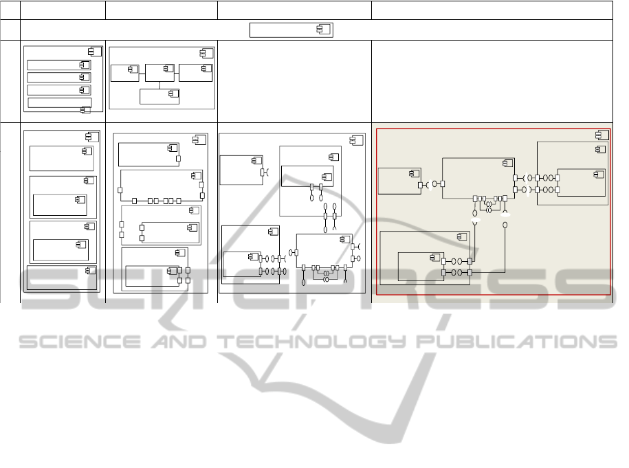
4.1 Illustration via the ERCMS
Based on this case study, we perform the transition
from the style level, presented in (Figure 2) through
UML meta-models, to the instance level (Figure 6).
We applied successive refinements and implemented
the previously described model transformation rules.
We obtained then the following results: In Sv
0
, we ap-
ply the R
0
rule to define the application named “ER-
CMS" .
We obtain the level Sv
1
through the « Insert »
transformation operation (Figure 3). In fact, partici-
pants in the ERCMS are represented (in Sv
1
/Sh
0
) by
their components, named supervisor, coordinator, in-
vestigator, and manager. Those participants commu-
nicate with each other via the manager. Those rela-
tionships are represented (in Sv
1
/Sh
1
) as UML associ-
ations while applying the “Insert" transformation op-
eration (Figure 4).
Finally, we illustrate instances obtained in Sv
2
:
Sv
2
/Sh
0
presents two composites of type coordinator
and investigator, only one manager and only one su-
pervisor. We specify the role of each component of
the application. Thus, the supervisor of the mission
plays the role of a component consuming events and
will be defined as “Consumer". In the same way,
we specify the roles of each type. A manager is
the “Events-service", an investigator and a coordina-
tor have the role of “Producer-Consumer". Sv
2
/Sh
1
illustrates the list of the ports for each component.
Indeed, coordinators and investigators communicate
with each other symmetrically as peers, adopting a
protocol that allows a bidirectional flow of commu-
nication. So, we choose the topology “Network-
Dispatcher-AcyclicPeerToPeer". Sv
2
/Sh
2
assigns to
each port an interface of the type provided or required
according to the type of service. Sv
2
/Sh
3
establishes
connections according to this topology and defines the
style “Publish-Subscribe".
Finally, we reach a fine-grain description at scale
Sv
2
/Sh
3
. The ERCMS was presented as a whole. The
refinement steps allow us to compose the application,
to extract all design details which are related to com-
plexity, and to establish clear configurations.
5 CONCLUSION
In this paper, we have presented several studies re-
lated to the multi-level, multi-layer, multi-view , re-
finement architecture concepts. We have introduced a
multi-scale modelling approach for multi-level archi-
tectures based on UML component diagrams and sup-
porting adaptability management. We presented the
approach at the conceptual level and proposed UML
notations at the architectural style level. We have also
presented a description of the instance level through a
case study. We have then presented the rules of refine-
ment/abstraction through model transformation tech-
niques. Finally, we have provided verification rules of
intrinsic properties for model traceability. We are cur-
rently working on the improvement of the validation
scope of our approach based on a notational correc-
tion through XML and semantic correction. In our
future work, we expect to apply our multi-scale ap-
proach to other use cases for modeling complex sys-
tem architectures (e.g. Systems of Systems).
ICEIS2015-17thInternationalConferenceonEnterpriseInformationSystems
380
Sh
0
Sh
1
Sh
2
Sh
3
Sv
0
Sv
1
Supervisor
Coordinator
Investigator
ERCMS
Manager
ERCMS
ERCMS
Manager
Supervisor
Coordinator
Investigator
« Consumer »
ERCMS
« Consumer »
ERCMS
ERCMS
«
ProdCons
»
«
ProdCons
»
ERCMS: Publish-Subscribe
Sv
3
« Consumer »
Supervisor
« EventDispatchers »
Manager
« ProdCons »
Coordinator
« ProdCons »
Coordinator
« ProdCons »
Investigator
« ProdCons »
Investigator
« Consumer »
Supervisor
« ProdCons »
Investigator
« ProdCons »
Investigator
« ProdCons »
Coordinator
« ProdCons »
Coordinator
« NetworkDispatcher-
AcyclicP2P »
Manager
« Consumer »
Supervisor
« ProdCons»
Investigator
« ProdCons »
Investigator
« ProdCons »
Coordinator
«
ProdCons
»
Coordinator
« NetworkDisp -
AcyclicP2P »
Manager
« NetworkDispatchers
-AcyclicP2P »
Manager
« Consumer »
Supervisor
«
ProdCons
»
Coordinator
« ProdCons »
Coordinator
« ProdCons »
Investigator
« ProdCons »
Investigator
Figure 6: Illustration via the ERCMS.
REFERENCES
Anwar, A., Ebersold, S., Coulette, B., Nassar, M., and Kri-
ouile, A. (2010). A rule-driven approach for com-
posing viewpoint-oriented models. Journal of Object
Technology, 9(2):89–114.
Baresi, L. and Guinea, S. (2013). Event-based multi-level
service monitoring. In ICWS 2013 IEEE 20th Inter-
national Conference on Web Services, pages 83–90.
Bouassida, I., Drira, K., Chassot, C., Guennoun, K., and
Jmaiel, M. (2010). A rule-driven approach for archi-
tectural self adaptation in collaborative activities using
graph grammars. Int. J. Auton. Comp., 1(3):226–245.
Brosch, F., Buhnova, B., Koziolek, H., and Reussner, R.
(2011). Reliability prediction for fault-tolerant soft-
ware architectures. In QoSA/ISARCS, pages 75–84.
Ferrucci, F., Nota, G., Pacini, G., Orefice, S., and Tor-
tora, G. (1992). On the refinement of logic specifica-
tions. International Journal of Software Engineering
and Knowledge Engineering, 02(03):433–448.
Juan, Z., Xiaojuan, B., Qiang, L., Jie, C., and di, W. (2010).
A component-based method for software architecture
refinement. In Proceedings of the 29th Chinese Con-
trol Conference.
Kallel, S., Hadj Kacem, M., and Jmaiel, M. (2012).
Modeling and enforcing invariants of dynamic soft-
ware architectures. Software and System Modeling,
11(1):127–149.
Khlif, I., Hadj Kacem, M., and Drira, K. (2012). An ap-
proach to multiscale and multi points of view descrip-
tion for dynamic software architectures. In CAL 6ème
Conférence francophone sur les architectures logi-
cielles, pages 162–168.
Khlif, I., Hadj Kacem, M., Hadj Kacem, A., and Drira, K.
(2014). A multi-scale modelling perspective for SoS
architectures. In Proceedings of the 2014 European
Conference on Software Architecture Workshops, EC-
SAW14, pages 30:1–30:5.
Lange, S. and Middendorf, M. (2010). Multi-level recon-
figurable architectures in the switch model. Journal
of Systems Architecture - Embedded Systems Design,
56(2-3):103–115.
Mallet, F., Lagarde, F., André, C., Gérard, S., and Terrier,
F. (2010). An automated process for implementing
multilevel domain models. In van den Brand, editor,
Software Language Engineering, volume 5969, pages
314–333. Springer.
Rafe, V., Reza, M., Miralvand, Z., Rafeh, R., and Hajiee, M.
(2009). Automatic refinement of platform indepen-
dent models. IEEE International conference on com-
puter technology and development, pages 397–411.
AUML-basedApproachforMulti-scaleSoftwareArchitectures
381
