
Nonlinear Control Design of VSC-MTDC Systems based on
Backstepping Approach
Mohamed Ayari
1
, Mohamed Moez Belhaouane
1,2
, Xavier Guillaud
2
and Naceur Benhadj Braiek
1
1
Advanced Systems Laboratory, Polytechnic School of Tunisia (EPT), University of Carthage,
BP. 743, 2078, La Marsa, Tunis, Tunisia
2
Laboratory of Electrical Engineering and Power Electronic (L2EP),
Ecole Centrale de Lille, BP 48, 59851 Villeneuve d’Ascq Cedex, France
Keywords:
VSC, HVDC, Nonlinear Backstepping Control Approach, Lyapunov Theory, Active Power Control Mode,
DC Voltage Control Mode.
Abstract:
This paper deals with the nonlinear control approach of Voltage Source Converter (VSC) based on MTDC
(multi-terminal direct current) transmission systems. A nonlinear control approach based on Backstepping
method is proposed for two different control methods: active power and DC voltage. The proposed control
approach, based on Lyapunov theory, is capable of analytically obtaining a control laws in order to regulate
the active power and dc bus voltage in an MTDC system. Furthermore, the dynamic interactions between the
active power nonlinear control design and the DC voltage droop control are examined. Finally, the validity
of the proposed control design approach is verified by time-domain simulations under the Matlab/ Simulink
environment.
1 INTRODUCTION
The development of the renewable energy requires a
reliable technology for transmission power over long
distances. Since of the disadvantage of the High Volt-
age Alterning Current (HVAC) and with the progres-
sion of the power electronics, the High Voltage Direct
Current (HVDC) technology is improved in (Setr
´
eus
and Bertling, 2008). The high power self-commutated
VSC, based on the Gate-Turn-Off (GTO) and Insu-
lated Gate Bipolar Transistor (IGBT) using the Pulse
Width Modulation (PWM) techniques, are the princi-
pal components in the transmission system HVDC. To
this end, they are used serve to providing high qual-
ity AC output voltage to the grid or even to a passive
load, and facilitate the control of the strongly coupled
nonlinear system (Jovic et al., 2003).
The VSC based multiterminal VSC-HVDC power
transmission system (VSC-MTDC) is an ideal ap-
proach to connect more then two HVDC station by a
DC grid (Jacobson, 2011). Recently, the new Mod-
ular Multilevel Converter (MMC) is attractive for
HVDC applications thanks to its modular structure
(Belhaouane et al., 2014).
Many research have been discussed the model-
ing and control of a VSC-MTDC transmission sys-
tem (Chen et al., 2006). Traditionally, the conven-
tional Proportional Integral PI controllers are used to
control the VSC-HVDC converters. However, the dy-
namic performance of such control scheme is poor,
because of the strong interactions among the control
loops (Rashed et al., 2008). The strong nonlinearity
present in the system dynamics requires the use of
nonlinear control techniques. Thus, a large number
of controller for HVDC transmission systems based
on different control techniques have been proposed to
enhance the transient systems and dynamic stability.
Several nonlinear control techniques are used to over-
come difficulties during abnormal operating condi-
tions especially under parametric uncertainties, faults
and non-linear disturbances (Ramadan et al., 2012).
Further, the application of advanced nonlinear
controls that is: robust control (Ramadan et al.,
2008), (Moharana and Dash, 2010), optimal control
(Sachdev et al., 1973), adaptive control (Reeve and
Sultan, 1994), and controls-based on artificial intel-
ligence (AI) (Dash et al., 1999), (Moharana et al.,
2006), have been developed for improving transient
stability of power systems (Colbia-Vega et al., 2008).
These approaches are used to elaborate complex non-
linear controllers, characterized by a lack of complete
knowledge of the dynamic characteristics of the sys-
tem.
Recently, the Backstepping control design tech-
596
Ayari M., Belhaouane M., Guillaud X. and Benhadj Braiek N..
Nonlinear Control Design of VSC-MTDC Systems based on Backstepping Approach.
DOI: 10.5220/0005545305960602
In Proceedings of the 12th International Conference on Informatics in Control, Automation and Robotics (ICINCO-2015), pages 596-602
ISBN: 978-989-758-122-9
Copyright
c
2015 SCITEPRESS (Science and Technology Publications, Lda.)

niques have received an important attention because
of its systematic and recursive design methodol-
ogy for nonlinear feedback control (Jammazi, 2008),
(Kim and Kim, 2003). In (Ruan et al., 2007), an
adaptive Backstepping control method is proposed
and uncertainties of AC grid current is considered.
(Wang et al., 2013) proposed a Backstepping control
design to ensure the stability of VSC-HVDC system
in case of a parameter variations and external distur-
bances. To control an MTDC system, a feedback lin-
earization strategy and Backstepping-like procedure
are proposed in (Chen et al., 2013).
In this manuscript, an integral Backstepping con-
trol scheme is presented and applied on a multi-
terminals VSC-HVDC transmission systems in order
to regulate the reactive power, active power and the
DC voltage where an integral action is added to en-
sure zero steady -state tracking error.
This paper is structured as follows. The math-
ematic model of VSC-MTDC station is given in 2.
Based on Lyapunov theory, an integral Backstepping
controller for each control mode is depicted in 3. Sec-
tion 4 presents the simulation results by using Mat-
lab/Simulink environment. At last, Conclusions are
drawn in Section 5.
2 MODELING OF VSC-MTDC
SYSTEM
In Fig. (1), the topology of Multi-terminal VSC-
MTDC for interconnexion between n AC networks
is depicted. It consists of DC cables with different
length, identical voltage source converters (VSCs),
and AC grids.
Figure 1: The interconnection between n terminals.
The configurations of the VSCs converter stations
are identical. In Fig. 2, one VSC terminal is shown.
L
s
and R
s
denote the inductance and the equivalent
resistance of the converter inductor respectively.
~
i
s
,
~u
m
and ~u
g
represent respectively the three phase AC
current and the voltages of the both side of the reactor
phase. The control of an MTDC transmission systems
consist to control the VSCs converter either by DC
bus voltage droop control mode ”Us-Control” or AC
power control mode ”Pac-Control”. The Pac-Control
mode aim to control the active and reactive powers.
The Us-Control mode allows to maintain the balance
between power production and demand.
2.1 Average Model: Pac-Control Mode
The basic structure of the three phase VSC converter
is depicted in Fig. 2. In Pac-Control mode, The DC
voltage is considered fix. Applying Kirchhoff’s volt-
age and current laws, it easy to obtain.
L
s
d
~
i
s
dt
+ R
s
~
i
s
= −~u
m
+~u
g
(1)
Multiplying each term of the equation (1) by the Park
matrix P
k
, it follows that:
P
k
d
~
i
s
dt
= −
R
s
L
s
P
k
~
i
s
−
1
L
s
P
k
~u
m
+
1
L
s
P
k
~u
g
(2)
where P
k
is the park transformation.
According to (2), the mathematical model of a VSC-
HVDC station operating on Pac-Control mode is writ-
ten as follows:
di
sd
dt
= −
R
s
L
s
i
sd
+ ωi
sq
−
1
L
s
u
md
+
1
L
s
u
gd
di
sq
dt
= −ωi
sd
−
R
s
L
s
i
sq
−
1
L
s
u
mq
+
1
L
s
u
gq
(3)
where i
sd
, i
sq
are the dq components of the VSC out-
put current, u
md
, u
mq
and u
gd
, u
gq
are the dq compo-
nents of the VSC output voltage, AC network voltage
respectively.
2.2 Average Model: Us-Control Mode
In the ”Pac-Control mode” presented above, the DC
voltage is considered as constant voltage variable and
presented by a fixed voltage DC source. Referring
to Fig. 2 with the DC circuit ”Us-Control”, the DC
source is replaced now by the capacitor equivalent C
s
and current source.
By assuming a dq frame orientation such that
u
gq
= 0 pu and neglecting the power losses on both
sides of the VSC converter, we get (Thomas et al.,
2001) :
P
AC
= P
DC
=⇒ u
s
i
m
=
3
2
u
gd
i
sd
+ u
gq
i
sq
(4)
where i
m
is the DC output current.
Using Eq. (3)-(4), we can obtain the following av-
erage model of the VSC-HVDC station operating on
NonlinearControlDesignofVSC-MTDCSystemsbasedonBacksteppingApproach
597
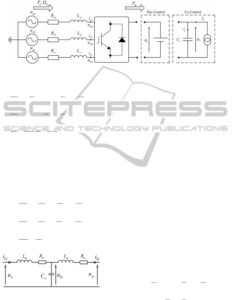
Figure 2: Basic structure of VSC converter.
Us-Control mode:
di
sd
dt
= −
R
s
L
s
i
sd
+ ωi
sq
−
1
L
s
u
md
+
1
L
s
u
gd
di
sq
dt
= −ωi
sd
−
R
s
L
s
i
sq
−
1
L
s
u
mq
du
s
dt
=
3u
gd
2C
s
i
sd
u
s
−
1
C
s
P
l
u
s
(5)
2.3 DC Cable Model
The model of the DC transmission line connected to
the DC side of i
th
and j
th
stations, is an equivalent
circuit of T-type. L
sr
, R
sr
and C
sr
denote respectively
the equivalent inductance, resistance and capacitance
of the cables. Then, the model of the DC cables is
described as:
di
l
i j
dt
= −
R
sr
L
sr
i
l
i j
−
1
L
sr
u
l
i j
+
1
L
sr
u
s
i
di
l
ji
dt
= −
R
sr
L
sr
l
ji
−
1
L
sr
u
l
i j
+
1
L
sr
u
s
j
du
l
i j
dt
=
1
C
sr
i
l
i j
+ i
l
ji
(6)
Figure 3: Simplified structure of DC cable (Thomas et al.,
2001).
3 INTEGRAL BACKSTEPPING
CONTROL SCHEME FOR
VSC-MTDC SYSTEMS
In this section, we propose a backstepping control
strategy including an integral action to ensure zero
steady-state tracking error. The proposed backstep-
ping controller is designed to keep the non-linearities
useful to enhance the performance and robustness of
control, unlike linearization methods. The determina-
tion of the control laws resulting from this approach
is based on Candidate Lyapunov Functions (CLF)
(Khalil, 2002), (Skjetne and Fossen, 2004).
The control purpose of an MTDC System is to reg-
ulate the DC voltage and to keep the power flow at its
reference value. The first VSC terminal controlling
both active and reactive powers, and all other termi-
nals are endowed with voltage droop controller (Dier-
ckxsens et al., 2012).
3.1 Integral Backstepping Controller of
Pac-control Mode
This control mode aims to regulate the active and re-
active powers. Considering the currents errors z
isd
and
z
isq
defined by:
z
isd
= I
re f
sd
− i
sd
z
isq
= I
re f
sq
− i
sq
(7)
Differentiating z
isd
and z
isq
with respect to time gives:
˙z
isd
=
˙
I
re f
sd
+
R
s
L
s
i
sd
− ωi
sq
+
1
L
s
u
md
−
1
L
s
u
gd
˙z
isq
=
˙
I
re f
sq
+ ωi
sd
+
R
s
L
s
i
sq
+
1
L
s
u
mq
. (8)
where
˙
I
re f
sd
and
˙
I
re f
sq
are the time derivative of I
re f
sd
and
I
re f
sq
, respectively.
ICINCO2015-12thInternationalConferenceonInformaticsinControl,AutomationandRobotics
598
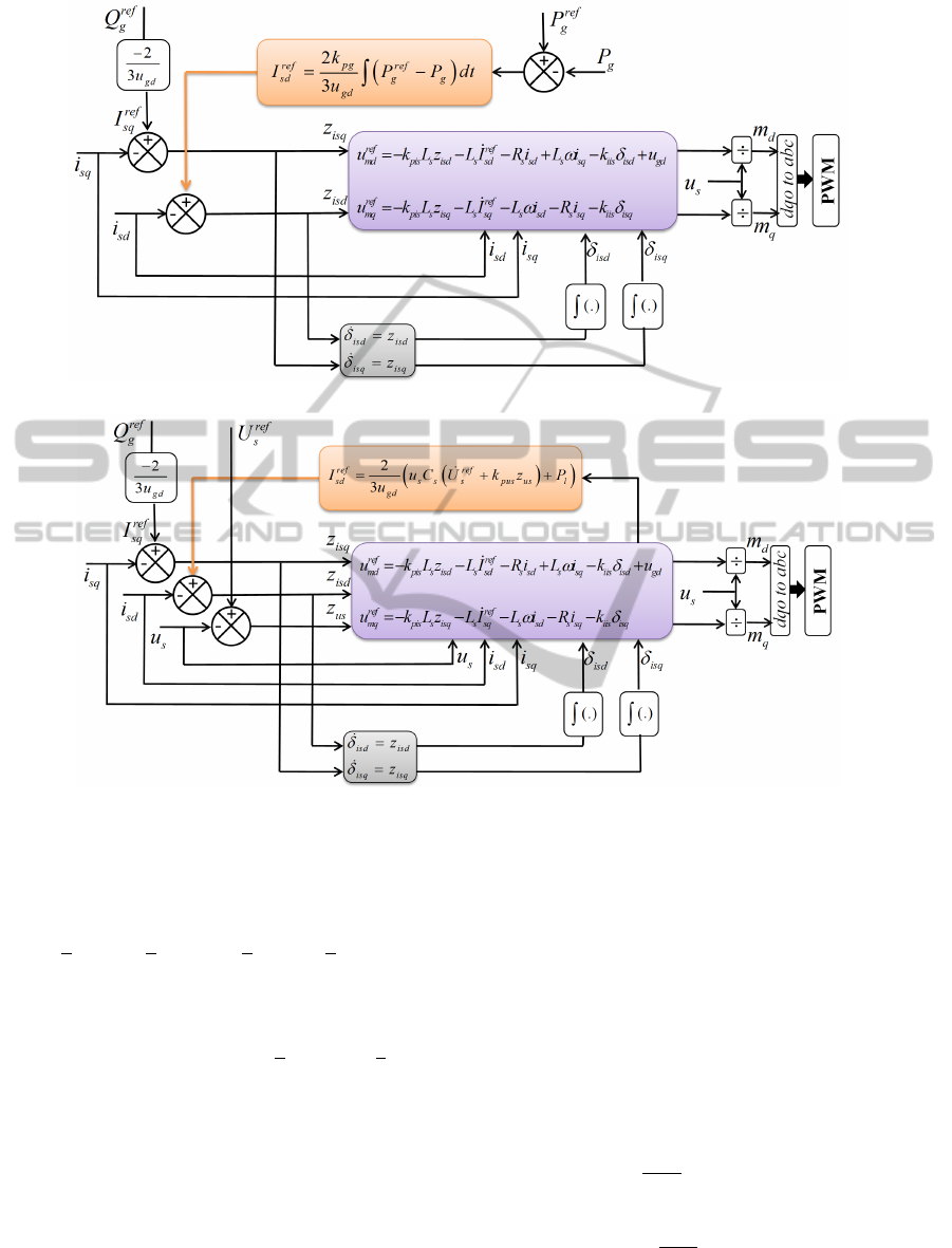
Figure 4: Block diagram of Backstepping method with integral action for P
ac
-Control Mode.
Figure 5: Block diagram of Backstepping method with integral action for U
s
-Control Mode.
To investigate the stability of the errors model (7), a
Lyapunov function V
PQ
is chosen as:
V
PQ
=
1
2
L
s
z
2
isd
+
1
2
k
iis
δ
2
isd
+
1
2
L
s
z
2
isq
+
1
2
k
iis
δ
2
isq
(9)
where δ
isd
and δ
isq
are respectively the integral terms
of z
isd
and z
isq
, k
iis
> 0. The terms
1
2
L
s
z
2
isd
and
1
2
L
s
z
2
isq
represent the energy fluctuation of the AC reactance.
The derivative of V
PQ
along the trajectories of (7) is
given by:
˙
V
PQ
= z
isd
L
s
˙
I
re f
sd
+ R
s
i
sd
− L
s
ωi
sq
+ u
md
− u
gd
+ z
isq
L
s
˙
I
re f
sq
+ L
s
ωi
sd
+ R
s
i
sq
+ u
mq
+k
iis
δ
isd
z
isd
+ k
iis
δ
isq
z
isq
(10)
which leads to the following control laws:
u
re f
md
= −k
pis
L
s
z
isd
− L
s
˙
I
re f
sd
− R
s
i
sd
+ L
s
ωi
sq
−k
iis
δ
isd
+ u
gd
u
re f
mq
= −k
pis
L
s
z
isq
− L
s
˙
I
re f
sq
− L
s
ωi
sd
− R
s
i
sq
− k
iis
δ
isq
(11)
yields:
˙
V
PQ
= −k
pis
L
s
z
2
isd
+ z
2
isq
< 0 (12)
where k
pis
> 0.
The active and reactive powers are controlled through
the currents i
sd
and i
sq
respectively, such as:
I
re f
sd
=
2k
pg
3u
gd
Z
t
0
P
re f
g
− P
g
dt
I
re f
sq
= −
2
3u
gd
Q
re f
g
(13)
The Backstepping control structure is deciped by Fig.
4.
NonlinearControlDesignofVSC-MTDCSystemsbasedonBacksteppingApproach
599

3.2 Integral Backstepping Controller of
Us-droop Control Mode
In this section, a droop voltage controller is designed
to stabilize the DC voltage, decoupling the dq grid
current and regulate the reactive power.
We consider the mathematical model given in (5).
Firstly, we introduce z
us
= U
re f
s
− u
s
, z
isd
= I
re f
sd
− i
sd
,
z
isq
= I
re f
sq
− i
sq
,
˙
δ
isd
= z
isd
and
˙
δ
isq
= z
isq
.
The time derivative of z
us
is given as:
˙z
us
=
˙
U
re f
s
−
3u
gd
2C
s
I
re f
sd
u
s
+
1
C
s
P
l
u
s
(14)
Let consider the following definite positive Lyapunov
function:
V
us
=
1
2
C
s
z
2
us
(15)
such that
1
2
C
s
z
2
us
represents the energy fluctuation in
the dc capacitor.
From the equation (5), the derivative of V
us
along the
trajectories of the system is given by:
˙
V
us
= C
s
z
us
˙
U
re f
s
−
3u
gd
2C
s
I
re f
sd
u
s
+
1
C
s
P
l
u
s
!
(16)
Then, if z
isd
= 0 and following the backstepping
method in order to ensure stability of the tracking
voltage, the virtual control law I
re f
sd
is given by the
following equation:
I
re f
sd
=
2
3u
gd
u
s
C
s
˙
U
re f
s
+ C
s
k
pus
u
s
z
us
+ P
l
(17)
Based on the above analysis, we get
˙
V
us
as negative
semidefinite function expressed as:
˙
V
us
= −k
pus
C
s
z
2
us
< 0 , k
pus
> 0 (18)
After the conception of the virtual controller, the sec-
ond step is to ensure the asymptotic stability of the
global system via the direct Lyapunov method based
on the new CLF. Then, differentiating the currents er-
rors z
isd
and z
isq
with respect to time yields:
˙z
isd
=
˙
I
re f
sd
+
R
s
L
s
i
sd
− ωi
sq
+
1
L
s
u
md
−
1
L
s
u
gd
˙z
isq
=
˙
I
re f
sq
+ ωi
sd
+
R
s
L
s
i
sq
+
1
L
s
u
mq
. (19)
where
˙
I
re f
sd
and
˙
I
re f
sq
are the time derivative of I
re f
sd
and
I
re f
sq
, respectively.
The candidate Lyupanov Function chosen for the
asymptotic stability of the global system is expressed
as:
V
PQ
= V
us
+
1
2
L
s
z
2
isd
+
1
2
k
iis
δ
2
isd
+
1
2
L
s
z
2
isq
+
1
2
k
iis
δ
2
isq
(20)
where k
iis
> 0.
The derivative of V
PQ
is given by:
˙
V
PQ
= z
isd
L
s
˙
I
re f
sd
+ R
s
i
sd
− L
s
ωi
sq
+ u
md
− u
gd
+ z
isq
L
s
˙
I
re f
sq
+ L
s
ωi
sd
+ R
s
i
sq
+ u
mq
+k
iis
δ
isd
z
isd
+ k
iis
δ
isq
z
isq
− k
pus
C
s
z
2
us
(21)
Similarly, by choosing the control laws as:
u
re f
md
= −k
pis
L
s
z
isd
− L
s
˙
I
re f
sd
− R
s
i
sd
+ L
s
ωi
sq
−k
iis
δ
isd
+ u
gd
u
re f
mq
= −k
pis
L
s
z
isq
− L
s
˙
I
re f
sq
− L
s
ωi
sd
− R
s
i
sq
− k
iis
δ
isq
(22)
˙
V
PQ
, expressed by (23), is negative semidefinite.
˙
V
PQ
= −k
pus
C
s
z
2
us
− k
pis
L
s
z
2
isd
− k
pis
L
s
z
2
isq
< 0 (23)
where k
pis
> 0.
Fig. 5 shows the structure of the control sys-
tem derived from the second step of the Backstepping
technique.
4 VALIDATION OF THE
PROPOSED NONLINEAR
CONTROL METHOD
To prove the effectiveness of the proposed control
strategy, a simulation study was carried out under
Matlab/Simulink environment. The test system is de-
picted in Fig. 6. It’s composed on two onshore and
offshore stations. It is worth pointing that each VSC
converter is rated at 1000 MVA, 320 kVrms phase to
phase AC voltage and a DC voltage of ± 320 kV.
Figure 6: A three-terminal VSC-HVDC transmission sys-
tem (Rault, 2014).
ICINCO2015-12thInternationalConferenceonInformaticsinControl,AutomationandRobotics
600
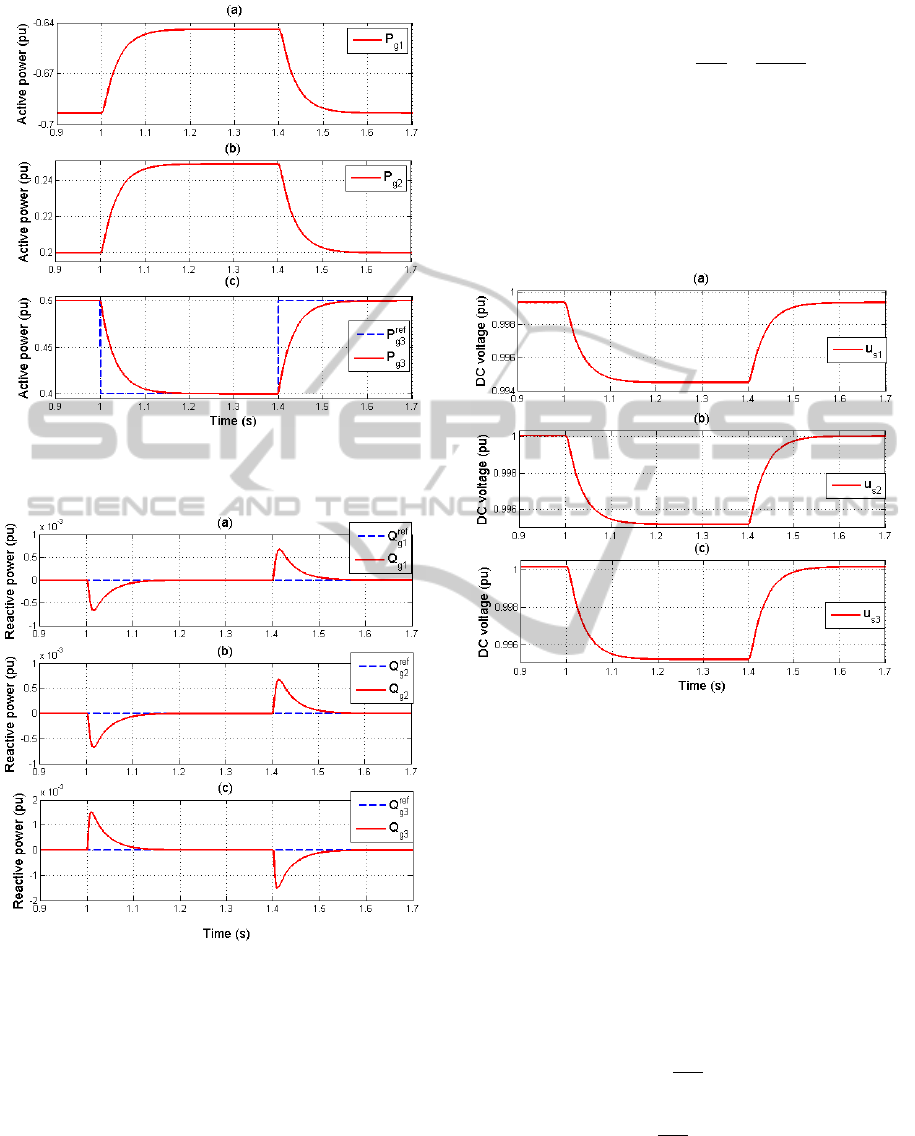
Figure 7: Behaviors of the active powers in the station n
◦
1,
n
◦
2 and n
◦
3.
Figure 8: Behaviors of the reactive powers in the station n
◦
1, n
◦
2 and n
◦
3.
The major contribution is based on the control de-
sign devoted to endow the station n
◦
1 and station n
◦
2
with the Us-droop control as well as controlling the
power flow via the station n
◦
3.
The control gains (k
pus
= 500, k
pg
= 30,
k
pis
= 10
3
and k
iis
= 119.36) are synthesised in
order to ensure a response time for the grid currents
around 10 ms, a response time for the active power
equal to 100 ms and to define the droop value K to
adjust the power deviation portion which is following
through a converter station:
K
KV
MW
=
∆u
s
∆P
g
=
1
C
s
k
pus
(24)
where:
• K is the droop value;
• ∆P
g
is deviation of power injected into the AC
grid;
• ∆u
s
is deviation of DC voltage.
Figure 9: DC voltage behavior in the stations n
◦
1, n
◦
2 and
n
◦
3.
Figs. (7)-(9) illustrate the behaviors of active power
and DC bus voltage for each stations. At instant t < 1
s, the power delivered by the wind farm is 0.5 pu (500
MW). The power injected through the station n
◦
2 to
the DC grid is 0.2 pu (200 MW) and the power flow
from DC grid to AC grid through station n
◦
1 is 0.7 pu
(700 MW). For instants t between 1 s and 1.1 s, the
produced power by wind farm is decreased to 0.4 pu
(400 MW). This loss of production is equally shared
between the two onshore converter stations when they
have the same droop value:
P
g1
= −700 +
100
2
= −650MW
P
g2
= 200 +
100
2
= 250MW
As shown in Fig. 9, this event leads to decrease the
DC voltage level since there is less power transfer
with regard to the previous operating point.
Simulations results (not shown here) show that the
NonlinearControlDesignofVSC-MTDCSystemsbasedonBacksteppingApproach
601

direct and quadrature current are decoupled. From
Fig. 8, the reactive powers of each station is always
track the reference signal Q
re f
gi
= 0 pu (i=1,2,3).
5 CONCLUSION
In this paper, the Backstepping control technique
based on direct Lyapunov method is extrapolated to
the VSC-MTDC application. The controller is able
to provide asymptotic stability for the power trans-
mission system with multiple terminals. The con-
trol law is based on a Backstepping-like procedure
which the stability of the whole transmission system
is proved under the proposed controller. Simulations
results show that the proposed control strategy is able
to regulate the DC-bus voltage and the power flow
with good dynamic performances.
REFERENCES
Belhaouane, M., Saad, H., and Guillaud, X. (2014). Con-
trol and performance of modular multilevel converters
using resonant controller. Dallas. 40
th
Annual Confer-
ence on IEEE Industrial Electronics Society, IECON.
Chen, H., Xu, Z., and Zhang, F. (2006). Nonlinear con-
trol for vsc based hvdc system. Montreal, Que. IEEE,
Power Engineering Society General Meeting.
Chen, Y., Dai, J., Damm, G., and Lamnabhi-Lagarrigue, F.
(2013). Nonlinear control design for a multi-terminal
vsc-hvdc system. Zrich, Switzerland. European Con-
trol Conference (ECC).
Colbia-Vega, A., de Leon-Morales, J., Fridman, L., Salas-
Peaa, O., and Mata-Jim
´
enez, M. (2008). Robust exci-
tation control design using sliding-mode technique for
multimachine power systems. Electric Power Systems
Research, 78(9):1627 – 1634.
Dash, P., Routray, A., and Mishra, S. (1999). A neural net-
work based feedback linearising controller for hvdc
links. Electric Power Systems Research, 50(2):125 –
132.
Dierckxsens, C., Srivastava, K., Reza, M., Cole, S., Beerten,
J., and Belmans, R. (2012). A distributed dc voltage
control method for vsc mtdc systems. Electric Power
Systems Research, 82(1):54 – 58.
Jacobson, B. (2011). Abb power systems, developments in
multiterminal hvdc. IEEE EPEC, Winnipeg Manitoba.
Jammazi, C. (2008). Backstepping and partial asymptotic
stabilization: Applications to partial attitude control.
International Journal of Control, Automation, and
Systems, 6(6):1 – 14.
Jovic, D., Lamont, L., and Xu, L. (2003). Vsc transmis-
sion model for analytical studies. volume 3. IEEE,
Power Engineering Society General Meeting, Confer-
ence Proceeding.
Khalil, H. (2002). Nonlinear Systems. Prentice Hall, Upper
Saddle River, NJ 07458, 3rd. edition.
Kim, K. and Kim, Y. (2003). Robust backstepping control
for slew maneuver using nonlinear tracking function.
IEEE Trans. Control Syst. Technol., 11(6):822 – 829.
Moharana, A. and Dash, P. (2010). Input-output lineariza-
tion and robust sliding-mode controller for the vsc-
hvdc transmission link. IEEE Transactions on Power
Delivery, 25(3):1952 – 1961.
Moharana, A., Panigrahi, M., Panigrahi, B., and Dash, P.
(2006). Vsc based hvdc system for passive network
with fuzzy controller. pages 1 – 4, New Delhi. Inter-
national Conference on Power Electronics Drives and
Energy Systems PEDES.
Ramadan, H., Siguerdidjane, H., and Petit, M. (2008). Ro-
bust nonlinear control strategy for hvdc light transmis-
sion systems technology. pages 360 – 365, USA. 34
th
Annual Conference of the IEEE Industrial Electronics
Society IECON.
Ramadan, H. S., Siguerdidjane, H., Petit, M., and Kacz-
marek, R. (2012). Performance enhancement and ro-
bustness assessment of vsc-hvdc transmission systems
controllers under uncertainties. Electrical Power and
Energy Systems, 35:34 – 46.
Rashed, M., El-Anwar, M., and Youssef, F. (2008). Nonlin-
ear control scheme for vsc-hvdc transmission systems.
pages 468 – 491, Egypt. 34
th
Annual Conference of
the IEEE Industrial Electronics Society MEPCON.
Rault, P. (2014). Mod
´
elisation Dynamique et Commande
des R
´
eseaux
`
a Courant Continu Multi-Terminaux
Haute Tension. Th
`
ese de doctorat en genie electrique,
Doctorat delivr
´
e par l’ecole centrale de LILLE.
Reeve, J. and Sultan, M. (1994). Gain scheduling adaptive
control strategies for hvdc systems to accommodate
large disturbances. IEEE Transactions on Power Sys-
tems, 9(1):366 – 372.
Ruan, S., Li, G., Jiao, X., Sun, Y., and Lie, T. (2007).
Adaptive control design for vsc-hvdc systems based
on backstepping method. Electric Power Systems Re-
search, 77(5-6):559 – 565.
Sachdev, M., Fleming, R., and Chand, J. (1973). Op-
timal control of a hvdc transmission link. IEEE
Transactions on Power Apparatus and Systems, PAS-
92(6):1958 – 1965.
Setr
´
eus, J. and Bertling, L. (2008). Introduction to
hvdc technology for reliable electrical power systems.
pages 1 – 5, Sweden. PMAPS ’08 Proceedings of the
10th International Conference.
Skjetne, R. and Fossen, T. (2004). On integral control in
backstepping: Analysis of different techniques. vol-
ume 2, pages 1899 – 1904, Boston, Massachusetts.
American Control Conference.
Thomas, J., Poullain, S., and Benchaib, A. (2001). Analy-
sis of a robust dcbus voltage control system for a vsc
transmission scheme. pages 119 – 124, London UK.
Seventh International Conference on AC DC Power
Transmission.
Wang, G., Wai, R., and Liao, Y. (2013). Design of backstep-
ping power control for grid-side converter of voltage
source converter-based high-voltage dc wind power
generation system. IET Renewable Power Generation,
7(2):118 – 133.
ICINCO2015-12thInternationalConferenceonInformaticsinControl,AutomationandRobotics
602
