
Designing and Describing QVTo Model Transformations
Ulyana Tikhonova and Tim Willemse
Technische Universiteit Eindhoven, P.O. Box 513, 5600 MB Eindhoven, The Netherlands
Keywords:
Model Driven Engineering, Model Transformation, QVTo, Documentation, Software Design.
Abstract:
Model transformations are the key technology of MDE that allows for software development using models as
first-class artifacts. While there exist a number of languages that are specifically designed for programming
model transformations, in practice, designing and maintaining model transformations still poses challenges.
In this paper we demonstrate how mathematical notation of set theory and functions can be used for informal
description and design of QVTo model transformations. We align the mathematical notation with the QVTo
concepts, and use this notation to apply two design principles of developing QVTo transformations: structural
decomposition and chain of model transformations.
1 INTRODUCTION
Model transformations are the key technology of
Model Driven Engineering (MDE), as they allow for
software development using models as first-class ar-
tifacts. Employing model transformations as the key
development technology poses challenges typical for
software engineering, such as design, documentation,
and maintenance. To address these challenges one
needs to be able to describe model transformations in
an unambiguous and clear way.
Nowadays, there exist a number of languages
specifically devoted for implementing model trans-
formations, such as: ATL, QVT family of languages,
ETL, etc. These languages can be viewed as DSLs for
model transformations. Consequently, a notation for
designing and documenting programs written in such
languages should be specifically tailored to describ-
ing model transformations, thus disqualifying gen-
eral purpose notations such as UML. In the current
practice there exist no specific notation for describ-
ing model transformations (except those provided by
the model transformation languages themselves). The
common approach for documenting and/or explaining
model transformations is to use concrete examples of
their inputs and the corresponding outputs. Clearly,
this approach provides an incomplete picture of the
transformation and fails to give an overview of the
transformation design.
In this paper we focus on QVT-Operational
(QVTo), that was introduced as part of the MOF
(Meta Object Facility) standard (omg, 2011). QVTo
comprises both high-level concepts specific for model
transformation development, such as constructs of the
Object Constraint Language (OCL), traceability, in-
heritance of subroutines; and low-level concepts of
the imperative languages, such as loops, conditional
statements, explicit invocation of subroutines. Conse-
quently, using QVTo requires strong language exper-
tise. However, in practice QVTo is used by engineers
who are experts in their own domains but typically
have little to no computer science training and lack
the required language expertise.
Following our experience of developing and main-
taining a complex QVTo model transformation and
of teaching QVTo to students, we propose to adopt
the mathematical notation of functions and set theory
as a notation-independent approach for documenting,
explaining, and designing QVTo model transforma-
tions. Typically such mathematical concepts are fa-
miliar to most engineers. In this paper we demon-
strate how this notation can be aligned with the QVTo
concepts, and thus can be used for explaining QVTo
concepts and for documenting model transformations
(Section 3). Moreover, using this notation we for-
mulate two common design principles of developing
model transformations and show how the correspond-
ing organization structure and information flow can
be described (Section 4). We discuss and assess the
proposed approach based on interviews with QVTo
practitioners in Section 5. Related work is discussed
in Section 2. Conclusions and directions for future
work are given in Section 6.
401
Tikhonova U. and Willemse T..
Designing and Describing QVTo Model Transformations.
DOI: 10.5220/0005556004010406
In Proceedings of the 10th International Conference on Software Engineering and Applications (ICSOFT-EA-2015), pages 401-406
ISBN: 978-989-758-114-4
Copyright
c
2015 SCITEPRESS (Science and Technology Publications, Lda.)

2 RELATED WORK
The broad problem of supporting the whole life-
cycle of the model transformation development with
a proper description notation is raised by Guerra et al.
in (Guerra et al., 2013). In this study they propose a
family of different visual languages for various phases
of the development process: requirements, analy-
sis (testing), architectural design, mappings overview
and their detailed design. Although the authors state
that the resulting diagrams should guide the construc-
tion of the software artifacts, there is no discussion
in the paper on how to design model transformations.
We use a single mathematical notation for describing
three of the listed phases: architectural design (trans-
formation chains), mappings overview (function sig-
natures) and their detailed design (formulas).
The earlier works on a notation for describing
and designing model transformations, such as (Etien
et al., 2007) and (Rahim and Mansoor, 2008), pro-
pose graphical representations that are based on UML
class diagrams. The major disadvantage of such ap-
proaches is the difficulty to describe the organiza-
tional structure of a transformation and the infor-
mation flow through this structure from source to
target models. This challenge is addressed in the
visual notation of the MOLA transformation lan-
guage (Kalnins et al., 2004), that combines ‘struc-
tured flowcharts’ for describing a transformation al-
gorithm with (model) patterns for defining input and
output of a transformation. Though MOLA aims for
describing model transformations in an ‘easy readable
way’, it introduces a number of specific visual means,
which might require certain experience from a user.
The existing studies that specify model transfor-
mations using mathematical formalisms, e.g. (Idani
et al., 2013), aim for formal analysis of transforma-
tions rather than for designing and maintaining them.
Such research is orthogonal to ours, but it is interest-
ing to see if they can be combined.
3 NOTATION
A model transformation takes as an input one or more
source models and generates as an output one or more
target models. An algorithm for such generation is
defined in terms of source and target metamodels.
In particular, the smallest units of a model transfor-
mation (mappings in QVTo) are defined in terms of
classes and associations specified in the source and
target metamodels. In order to provide a description
of a model transformation using the mathematical no-
tation of set theory, we need to specify how we refer
to the metamodel concepts in this notation.
In the context of MDE, a metamodel is usually de-
fined using the MOF standard. This standard can be
seen as a subset of UML class diagrams. Following
a common approach when applying set theory to de-
scribe class diagrams, we will interpret classes intro-
duced by a metamodel as sets of objects that instan-
tiate this class. For instance, the example metamodel
depicted in Figure 1 introduces the sets StateMachine,
State, Transition, CompositeState, etc. To refer to the
associated classes, we use the dot notation common in
object-oriented languages (including QVTo); for in-
stance s.states where s ∈ StateMachine.
In general, a model transformation defines a rela-
tion between a set of source models and a set of tar-
get models (Czarnecki and Helsen, 2006). A QVTo
mapping is more restrictive, realizing a function that
maps one or more source model objects into one or
more target model objects. Thus, we can denote a
QVTo mapping as a function from a set representing
the source class to a set representing the target class.
For example, the simple mapping depicted in the line
1 of Listing 1 can be viewed as a function with the
following signature:
CloneTransition : Transition → Transition (1)
Mappings with multiple inputs and/or outputs can
be treated in the same way, using Cartesian products
of sets to indicate these inputs and/or outputs; e.g. the
QVTo mappings of lines 2 and 3 in Listing 1 can be
represented as follows:
MultTrans : Transition × State
→ Transition
(2)
MultState : State × State → State (3)
QVTo also allows a collection of objects to be
used as an input and/or output of a mapping (line 4
in Listing 1). To indicate this we use the powerset
P(S) of a set S:
MultiplyStateMachines : P(StateMachine)
→ StateMachine
(4)
Function signatures allow us to concisely capture
the purpose of a mapping in terms of source and tar-
get metamodels. To describe what a mapping actu-
ally does, we need to describe how elements of target
objects are calculated from the elements of source ob-
jects. For this, we use formulas of the following form:
CloneTransition(self) :
trigger =
[
t∈self.trigger
{CloneTrigger(t)},
guard = CloneConstraint(self.guard),
effect =
[
e∈self.effect
{CloneBehavior(e)},
...
(5)
ICSOFT-EA2015-10thInternationalConferenceonSoftwareEngineeringandApplications
402
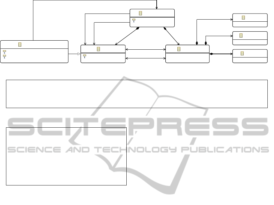
StateMachine
name : EString
Transition
Trigger
Constraint
Behavior
State
name : EString
CompositeState
/isSequential : EBoolean = true
/isOrthogonal : EBoolean = false
[0..*] transitions
[0..*] trigger
[0..1] guard
[0..*] effect
[1..*] submachine
[1..*] states
[0..*] in
[1..1] target
[0..*] out
[1..1] source
[1..1] initial
[0..*] final
Figure 1: Metamodel of the UML state machine.
1 mapping T r a n s i t i o n : : C l o n e T r a n s i t i o n ( ) : T r a n s i t i o n { . . . }
2 mapping T r a n s i t i o n : : M u l t Tran s ( i n s t a t e : S t a t e ) : T r a n s i t i o n { . . . }
3 mapping Tuple ( s1 : S t a t e , s 2 : S t a t e ) : : M u l t S t a t e ( ) : S t a t e { . . . }
4 mapping S et ( S t a t e M a c h i n e ) : : M u l t i p l y S t a t e M a c h i n e s ( ) : S t a t e M a c h i n e { . . . }
Listing 1: Mapping declarations of the example QVTo transformation.
1 mapping T r a n s i t i o n : : C l o n e T r a n s i t i o n ( )
2 : T r a n s i t i o n {
3 r e s u l t . t r i g g e r : = s e l f . t r i g g e r −>
4 map C l o n e T r i g g e r ( ) ;
5 r e s u l t . g uard := s e l f . g u a r d .
6 map C l o n e C o n s t r a i n t ( ) ;
7 r e s u l t . e f f e c t : = s e l f . e f f e c t −>
8 map C l o n e B e h a v i o r ( ) ;
9 . . . }
Listing 2: QVTo code of the CloneTransition mapping.
Formula 5 describes the QVTo mapping depicted
in Listing 2. It shows how each element of the target
object is calculated by the invocation of other map-
pings on elements of the source object. We denote
a calculation that is performed on a collection by a
quantified union over elements of the collection (lines
1 and 3 of the formula correspond to lines 3-4 and
7-8 of the listing). The invocation of a mapping is in-
dicated by the application of the corresponding func-
tion, such as CloneConstraint(self.guard).
4 DESIGN OF MODEL
TRANSFORMATIONS
Designing model transformations is a challenging
part of the model transformation development pro-
cess. When designing a model transformation one
must answer questions such as ‘what are the map-
pings that constitute a model transformation?’ and
‘how are these mappings related with each other, i.e.
invoked by each other?’. In practice, there exist a
number of design principles that developers can fol-
low when creating their model transformations (Lano
and Rahimi, 2014). In this section we demonstrate
how the presented mathematical notation can facili-
tate application of some of these design principles.
4.1 Structural Decomposition of Model
Transformations
Model transformations construct target models from
source models. Such models typically consist of
objects connected with each other by associations.
Therefore, mappings that constitute a model transfor-
mation should construct both target objects and the
associations between them. In QVTo each mapping
constructs a new object via assigning values to its
properties, i.e. by constructing objects it is associated
with. This observation is captured by the following
principle for designing model transformations:
mappings should be related to (invoked by)
each other in the same way as the objects that
they construct are associated with (composed
of) each other.
In other words, the structure of a model transforma-
tion follows the structure defined by the target meta-
model. In (Gerpheide et al., 2014), this was identi-
fied as one of the best practices for understandability
and maintainability of transformations. To apply this
principle in our design process we take the following
steps:
1. We identify the inputs and outputs of the transfor-
mation and define their structures,
2. We establish the correspondence between the ele-
ments in input and output structures,
3. We capture these correspondences in signatures of
the constituent mappings,
DesigningandDescribingQVToModelTransformations
403

4. We decompose the transformation into constituent
mappings.
In what follows, we show how these steps help de-
sign a mapping that takes two state machines and
constructs a state machine representing their product.
The source and target metamodel of this transforma-
tion is depicted in Figure 1. The function signature of
the mapping is as follows.
MultiplyTwoSTMs : StateMachine×
StateMachine → StateMachine
(6)
The task of writing such a transformation may not
seem challenging, taking into account that we know
the definition of a product of two state machines.
However, it might be not so obvious how to imple-
ment this transformation in QVTo code.
First, we identify the structure of the inputs
and outputs. For this we ‘rewrite’ each of the classes
in the initial function signature with the classes that
are associated with this one. The structure of the class
StateMachine is determined by a tuple of classes ref-
erenced through the associations states, transitions,
initial, and final. From this point of view, the class
StateMachine can be seen as the relation P(State) ×
P(Transition)× State×P(State).
1
Thus, as a result of
rewriting signature (6), we obtain the following:
(P(State) × P(Transition) × State × P(State))×
(P(State) × P(Transition) × State × P(State)) →
P(State) × P(Transition) × State × P(State)
(7)
Second, we connect elements in input to out-
put structures, i.e. we strive towards breaking down
the structure in the formula. To this end, we redis-
tribute the inputs on the left of the arrow and the out-
puts on the right of the arrow according to our un-
derstanding of which input elements are required to
construct which output elements. For example, we
know that the states of the resulting state machine
are constructed from the states of the input machines.
We capture this by grouping the input collections of
States and the output collection of States in a separate
sub-signature in Formula (8).
(P(State) × P(State) → P(State))×
(P(Transition) × P(Transition)×
P(State) × P(State)) → P(Transition))×
(State × State → State)×
(P(State) × P(State) → P(State))
(8)
We do the same for the output transitions, the initial
state, and the final states. The output transitions de-
pend both on the input transitions and on the input
1
Here we use the powerset P(S) of a set S to indicate
that multiplicity of an association end has an upper bound
greater than one.
states, thus we duplicate the input state collections on
the left of the arrow for the second sub-signature. The
resulting initial state is composed of the input initial
states, see the third sub-signature in Formula (8). The
same holds for the collection of final states, see the
fourth sub-signature in Formula (8).
Third, we derive signatures of the constituent
mappings. Each sub-signature, underlying the sig-
nature obtained in the previous step, captures a cor-
respondence between source and target objects. We
decompose the mapping MultiplyTwoSTMs into in-
vocations of the constituent mappings according to
these correspondences.
To derive signatures of the constituent mappings,
we consider each sub-signature separately. The first
sub-signature of Formula (8) is
P(State) × P(State) → P(State) (9)
In QVTo a P-symbol that appears evenly on both sides
of an arrow corresponds to the invocation of a map-
ping on an input collection and assigning the result of
this mapping to an output collection. If the mapping
operates on elements of the collections rather than on
the collections, then we can reduce the corresponding
collection symbols P. Mathematically, such a reduc-
tion of P-symbols corresponds to an inverse of func-
tion lifting. After applying this technique to signa-
ture (9), we derive the following underlying signature:
MultState : State × State → State (10)
The resulting mapping MultState constructs a state
of the target state machine as a pair of states from
the two source machines. The initial and final states
are constructed in the same way. Thus, the signature
of MultState can be derived from the first, third, and
fourth sub-signatures of formula (8).
Each output transition is a copy of an input tran-
sition duplicated as many times as its source and tar-
get states have been duplicated to construct the out-
put states. As each state of an input machine is paired
with all states of the other input machine, we conclude
that each transition of an input machine is paired with
all states of the other input machine. This knowledge
is captured by regrouping the corresponding collec-
tions in the second sub-signature of formula (8):
(P(Transition) × P(State))×
(P(Transition) × P(State)) → P(Transition)
(11)
The described pairing of transitions with states is ap-
plied symmetrically to both input machines. The tar-
get collection of transitions is constructed as the union
of the two resulting collections. Therefore, we reduce
signature (11) to the following underlying signature:
P(Transition) × P(State) → P(Transition) (12)
ICSOFT-EA2015-10thInternationalConferenceonSoftwareEngineeringandApplications
404

1 mapping Tupl e (m1: S t a t e M a c h i n e , m2: S t a t e M a c h i n e ) : : MultiplyTwoSTMs ( ) : S t a t e M a c h i n e
2 {
3 r e s u l t . s t a t e s : = m1 . s t a t e s −> c o l l e c t ( s1 | m2 . s t a t e s −> c o l l e c t ( s2 |
4 Tupl e { s t 1 = s1 , s t 2 =s 2 } . map M u l t S t a t e ( ) ) ) ;
5
6 r e s u l t . t r a n s i t i o n s : = m1 . t r a n s i t i o n s −> c o l l e c t ( t | m2 . s t a t e s −> c o l l e c t ( s |
7 t . map M u l t T r a n s ( s ) ) )
8 −> u n i o n ( m2 . t r a n s i t i o n s −> c o l l e c t ( t | m1 . s t a t e s −> c o l l e c t ( s |
9 t . map M u l t T r a n s ( s ) ) ) ) ;
10
11 r e s u l t . i n i t i a l : = Tuple { s t 1 =m1 . i n i t i a l , s t 2 =m2 . i n i t i a l } . map M u l t S t a t e ( ) ;
12 r e s u l t . f i n a l : = m1 . f i n a l −> c o l l e c t ( f 1 | m2 . f i n a l −> c o l l e c t ( f 2 |
13 Tupl e { s t 1 = f1 , s t 2 = f2 } . map M u l t S t a t e ( ) ) ) ;
14 }
Listing 3: QVTo code of the MultiplyTwoSTMs transformation.
Observing that we can once more use a reverse func-
tion lifting, we finally arrive at the following signature
for a constituent mapping:
MultTrans : Transition × State → Transition
(13)
Finally, we describe the implementation of a
mapping in a formula using the notation we intro-
duced in Section 3.
MultiplyTwoSTMs(m1, m2) :
states =
[
s1∈m1.states
[
s2∈m2.states
{MultState(s1, s2)},
transitions =
[
t∈m1.transitions
[
s∈m2.states
{MultTrans(t, s)} ∪
[
t∈m2.transitions
[
s∈m1.states
{MultTrans(t, s)},
initial = MultState(m1.initial, m2.initial),
final =
[
f 1∈m1.final
[
f 2∈m2.final
{MultState( f 1, f 2)}
(14)
After we have come up with the design of the map-
ping and captured it in a formula, we write the QVTo
code according to this formula. Listing 3 corresponds
to formula (14).
4.2 Chaining Model Transformations
The principle described in the previous section is
difficult to apply if source and target models have
very different structures; for example, if mappings
that match source and target elements are scattered
over the metamodels structures, or if there are mutual
dependencies between constructed objects. This type
of situation is described in the literature as structure
clash (Jackson, 2002), or semantic gap (van Amstel
et al., 2008). Such design difficulty is usually solved
using a chain of model transformations. In this way,
1 h e l p e r C o m p o s i t e S t a t e : : F l a t t e n ( )
2 : s t a t e s : Se t ( S t a t e ) ,
3 t r a n s i t i o n s : S e t ( T r a n s i t i o n )
4 {
5 r e t u r n s e l f . su b ma ch in e −>
6 map O r t h o g o n a l 2 S e q u e n t i a l ( ) .
7 map S u b s t i t u t e M a c h i n e ( s e l f . i n ,
8 s e l f . o u t ) ;
9 }
Listing 4: QVTo code of the Flatten transformation.
structure clash is managed in a chain of intermediate
steps each of which with a minimal clash.
A chain of model transformations can be de-
scribed using function composition: f (m) = ( f
1
◦
f
2
)(m), where a model transformation f : A → B has
a too wide gap between structures A and B, and there-
fore is split into model transformations f
1
: A → C and
f
2
: C → B. To construct a function composition, i.e.
to connect intermediate steps into a chain of model
transformation, we propose to use currying.
The example model transformation depicted in
Listing 4 flattens a state machine by removing its
composite states and replacing them with equivalent
sets of simple states and transitions. This transforma-
tion consists of two steps: (1) transform orthogonal
(parallel) composite state into a sequential composite
state, (2) substitute the submachine of the composite
state into the parent machine. The following formula
describes the chain of these two steps using function
composition and currying:
Flatten(state) =
(Orthogonal2Sequential(state.submachine)
◦ SubstituteMachine(state.in, state.out))
(15)
DesigningandDescribingQVToModelTransformations
405

5 DISCUSSION & VALIDATION
Above we demonstrated how the mathematical nota-
tion of set theory can be used to describe QVTo map-
pings, their signatures and implementations, to de-
rive organizational structure of mappings, and to de-
scribe the information flow in chains of model trans-
formations. In this paper, we did not discuss QVTo
constructs such as inheritance of mappings, impera-
tive statements, OCL expressions, recursion, etc. We
were, however, able to describe such concepts in a
larger application (for instance, inheritance of map-
pings can be described using union of functions; and
OCL expressions can be represented as predicates).
While the proposed approach for describing and de-
signing model transformations still requires further
investigation and experiments, we have the following
early validation results:
1. we applied the proposed approach when develop-
ing, documenting, and refactoring two different
model transformations;
2. feedback provided by QVTo practitioners on our
proposal (we performed three semi-structured in-
terviews with developers from three different af-
filiations and different engineering domains).
Based on our experience and on the feedback of the
QVTo practitioners, we conclude that:
• there is a need for a notation for documenting and
designing model transformations;
• the description of QVTo mappings in the form of
formulas is clear and understandable (also to en-
gineers with no computer science background);
• the design principles can assist in the creative pro-
cess of designing model transformations;
• designing a model transformation in the form of
formulas before coding it in QVTo improves read-
ability and understandability of the resulting code.
In addition to these results, we conclude that for the
successful application of the proposed notation the
following questions require further investigation:
• whether the proposed notation restricts the result-
ing design of a model transformation;
• what are the limits of the proposed notation,
whether all essential situations can be described.
6 CONCLUSION
In this paper we showed how the mathematical nota-
tion of set theory and functions can be used to explain
QVTo concepts, to facilitate the design process of
model transformations, and to document model trans-
formations. The resulting formulas give an overview
of the organizational structure and the information
flow of a transformation in an unambiguous and con-
cise way. To assess the applicability of this approach,
we applied it when designing, developing, and refac-
toring two model transformations
2
, one of which is
a complex transformation bridging a wide semantic
gap. Moreover, we performed interviews with QVTo
practitioners. While the results of these experiments
and interviews are positive, the approach requires fur-
ther investigation and experiments. In addition to the
research questions listed in Section 5, we aim to ex-
amine if the proposed approach is language indepen-
dent and can be used for developing in other model
transformation languages, e.g. ATL.
REFERENCES
(2011). Meta Object Facility (MOF) 2.0 Query/View/Trans-
formation Specification. OMG. Version 1.1.
Czarnecki, K. and Helsen, S. (2006). Feature-based Survey
of Model Transformation Approaches. IBM Syst. J.,
45(3):621–645.
Etien, A., Dumoulin, C., and Renaux, E. (2007). Towards a
Unified Notation to Represent Model Transformation.
Research Report 6187, INRIA.
Gerpheide, C. M., Schiffelers, R. R. H., and Serebrenik, A.
(2014). A Bottom-Up Quality Model for QVTo. In
QUATIC, pages 85–94. IEEE.
Guerra, E., de Lara, J., Kolovos, D., Paige, R., and dos
Santos, O. (2013). Engineering model transforma-
tions with transML. Software and Systems Modeling,
12(3):555–577.
Idani, A., Ledru, Y., and Anwar, A. (2013). A Rigorous
Reasoning about Model Transformations Using the B
Method. In BPMDS, pages 426–440.
Jackson, M. (2002). JSP in Perspective. In Broy, M. and
Denert, E., editors, Software Pioneers, pages 480–
493. Springer-Verlag New York, Inc.
Kalnins, A., Barzdins, J., and Celms, E. (2004). Model
Transformation Language MOLA. In MDAFA, pages
62–76.
Lano, K. and Rahimi, S. K. (2014). Model-transformation
design patterns. IEEE Trans. Software Eng.,
40(12):1224–1259.
Rahim, L. A. and Mansoor, S. B. R. S. (2008). Proposed De-
sign Notation for Model Transformation. In ASWEC,
pages 589–598. IEEE Computer Society.
van Amstel, M., van den Brand, M. G. J., Protic, Z., and
Verhoeff, T. (2008). Transforming Process Algebra
Models into UML State Machines: Bridging a Seman-
tic Gap? In ICMT.
2
The source code and the description of the transforma-
tion used as an example in this paper are available online at
code.google.com/p/qvto-flatten-stm/
ICSOFT-EA2015-10thInternationalConferenceonSoftwareEngineeringandApplications
406
