Two Body Dynamic Model for Speed Skating Driven by the Skaters
Leg Extension
E. van der Kruk, H. E. J. Veeger, F. C. T. van der Helm and A. L. Schwab
Department of Biomechanical Engineering, Delft University of Technology, Mekelweg 2, Delft, The Netherlands
Keywords: Speed Skating, Multi-Body Dynamics, Mathematical Model, Verification.
1 OBJECTIVES
In speed skating forces are generated by pushing in a
sideward direction against an environment, which
moves relative to the skater. De Koning et al. (1987)
showed that there is a distinct difference in the
coordination pattern between (elite) speed skaters.
Models can help to give insight in this peculiar
technique and ideally find an optimal motion pattern
for each individual speed skater. Currently there are
three models describing and optimizing the
behaviour and performance of skaters, of which only
two are relevant in terms of coordination patterns
(Allinger and Bogert 1997; Otten 2003). However,
none of them have been shown to accurately predict
the observed coordination pattern via verification
with empirical kinetic and kinematic data.
Therefore, the objectives of this study are to present
a verified three dimensional inverse skater model
with minimal complexity, based on the idea of
(Cabrera et al. 2006), modelling the speed skating
motion on the straights. The model is driven by the
changing distance between the torso and the skate
(further referred to as the leg extension), which is
also the true input of the skater to generate a global
motion. This input, which is indirectly also a
measure of the knee extension of the skater, is a
variable familiar to the speed skaters and coaches. In
this extended abstract we verify this novel model for
two strokes (left and right) of one skater through
correlation with observed kinematics and forces.
2 METHODS
2.1 Model Description
The model presented in this section simulates the
upper body transverse translation of the skater
together with the forces exerted by the skates on the
ice. The model input is the measured leg extension
(coordination pattern). Based on empirical data from
previous studies using elite skaters, the double
stance phase, the time in which both skates are in
contact with the ice, is rather short. For the sake of
simplicity, we assume that there is only one skate at
a time in contact with the ice, alternating left and
right. The point of alternation is defined as the
moment in time where the forces exerted on both
skates are equal. Furthermore the arm movements
and the rotations of the upper body are assumed to
be of marginal effect on the overall power and are
therefore neglected. Based on these assumptions, the
skater can be considered as a combination of two
point masses, which are situated at the upper body
(mass B) and at each (active) skate (mass S). The
body mass of the skater is distributed over the two
active masses by a constant mass distribution
coefficient (η) to compensate for the shift in the
center of mass position during the speed skating
movement. Each mass has three degrees of freedom.
The set of parameters is restricted to the position
coordinates of mass B (
,,
bbb
x
yz
), two translations
in the transverse plane of mass S with the position
coordinates (
,
s
s
x
y
) (because the skate is assumed
to be on the ice, making z
s
=0 at all times) and one
rotation in the same plane, the steer angle (φ
S
). The
orientation of the skate is of importance for the
constraint forces acting on the skate. All other
rotations of the skates are ignored.
Since we want to obtain a model which is driven
by generalized (local) coordinates, we introduce a
set of generalized coordinates
i
q (Figure 2), so the
global coordinates can be expressed in terms of leg
Kruk, E., Veeger, H., Helm, F. and Schwab, A..
Two Body Dynamic Model for Speed Skating Driven by the Skaters Leg Extension.
Copyright
c
2015 by SCITEPRESS – Science and Technology Publications, Lda. All rights reserved
extension via the kinematic relation
()
ii
xfq=
.
These generalized coordinates consist of the leg
extension (
,,,
ssss
wuv
θ
)(Figure 2), that is actively
controlled by the skater and therefore serves as the
input coordinates to the model and the generalized
coordinates of the upper body (
,
bb
uv
), which will
be a result of the system dynamics (equal to
,
bb
xy
)
The equations of motion are expressed in
generalized coordinates, so that the constraints are
inherently fulfilled. Since we assume no lateral slip,
a non-holonomic constraint acting in the lateral
direction of the skate was added, causing the
undetermined external force λ perpendicular to the
skate blade in the transverse plane. This leaves a
model with two degrees of freedom in position and
only one in velocity. The known external forces
acting on the model are the air frictional forces and
the ice frictional forces.
2.2 Solving the Model
The model is solved in two steps. First, since the
parameters (
,,,
ssss
wuv
θ
) are considered inputs
and the air frictional forces acting on the upper body
are assumed to be known, the constraint force λ and
the transverse position of the upper body (
,
bb
uv
)
can be determined by means of integration (Runge
Kutta method), starting from the initial condition
()
,0 ,0 ,0 ,0
,,,
bbbb
xyxy
. The constraint is fulfilled for
each integration step by a projection method. Hereby
a minimization problem was formulated, concerning
the distance from the predicted solution to the
solution which is on the constraint surface. The
global coordinates
i
x
, which are the global
positions of the upper body and the skate, can then
be found analytically via the kinematic relation.
Finally, with the found upper body position and
λ
,
the local forces acting on the skate can be solved
analytically such that a complete two-body dynamic
model of the skater has been established.
2.3 Model Verification
The purpose of the model verification is to quantify
the error between the simulated data and the
measured forces and positions. The forces were
measured by a set of instrumented klapskates (van
der Kruk et al. 2015). The position of the masses
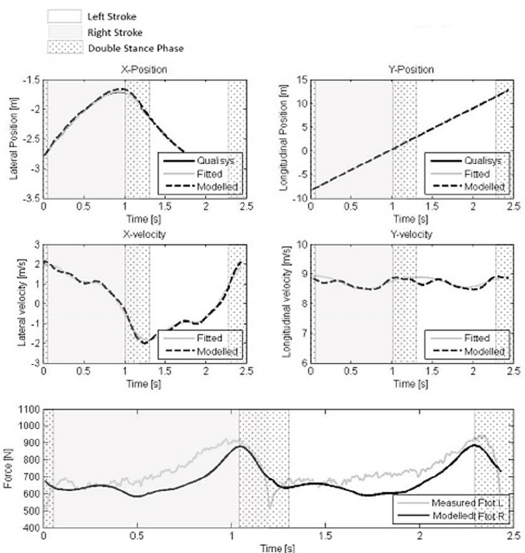
Figure 1: The fitted data of two consecutive strokes for position and velocity of mass B and the total force. The grey area
indicates a left stroke, the white area a right stroke, the pattern indicates the double stance phase as measured.. Y is in line
with the skate lane, X is perpendicular to the skate lane.

Table 1: Error between the simulated data and the measured data.
RMSE Mean Error SD Error Jmin
x-position 0.025 [m] 0.019 [m] 0.016 [m] 0.000310
y-position 0.045 [m] 0.033 [m] 0.031 [m] 0.000004
x-velocity 0.116 [m/s] 0.002 [m/s] 0.117 [m/s] 0.0028
y-velocity 0.096 [m/s] -0.048 [m/s] 0.084 [m/s] 0.000123
F 82 [N] -54.0 [N] 61.8 [N] 0.0305
Figure 2: The global and generalized coordinates of the
two-mass skater model. Leg extension consists of vertical
distance (w
s
) and horizontal distance between the mass S
and mass B in heading direction (u
s
) and perpendicular to
heading direction (v
s
) and the heading of the skate (θ
s
)
(orientation).
was measured by a motion capture system on 50
meter of the straight part of the rink, with a passive
marker on the Lateral Malleolus (representing mass
S) and on the back near the Sacrum (representing
mass B). A parametric function was fitted to the
recorded data, consisting of a linear and a geometric
function, which could be differentiated twice in
order to obtain velocity and acceleration data. The
air and ice friction were estimated based on previous
papers (van Ingen Schenau 1982; De Koning et al.
1992). The body mass was assumed to be distributed
equally over mass S and mass B. In this abstract the
data of one Dutch elite female speed skater are
presented (65kg, 1.75m).
3 RESULTS
The results show that the model estimated the
forward position and velocity of mass B the best
(Jmin (based on (Cabrera et al. 2006))), followed by
the lateral position and velocity, which were all
within 1% accuracy. The model was least accurate
for the force determination (Table 1). The forces
were consistently estimated too low (Figure 2,
bottom graph).
4 DISCUSSION
4.1 Kinematic Complexity
Preliminary results presented in this abstract showed
that the model, despite the simplicity, was able to
simulate the upper body movement accurately. The
forces on the skate were underestimated, which can
be explained by the simplicity of the model. The
skater was considered as a combination of two point
masses, which moreover were situated at fixed
positions on the body parts, with each a mass half of
the total body weight. In reality there might however
be a different mass distribution and the CoM of
these bodies move throughout the movement.
Additionally, the changing distance between the two
masses (leg extension), was modelled piston-like
without any damping. Optimization of the mass
distribution and determination of the true CoM (with
a full body marker set) will improve the model
estimation. The model would also benefit from
improved acceleration measurements by adding
IMU’s.
Although the double stance phase was neglected
based on previous papers, the collected data showed
that the double stance phase is apparent in about
13% of the stroke. However the force on the inactive
skate is low during this phase and the results do not
seem influenced by this assumption.
4.2 Frictional Forces
The estimation of air and ice friction based on
previous papers, probably caused an inaccuracy in
the model outcome. Moreover, the air friction was
assumed to be only dependent on velocity, while the
friction coefficient might differ within a stroke, due
to change of frontal area and drag. It would be
interesting to determine the magnitude and
repeatability of this change, in order to relate this to
the model error, and to perhaps improve the
estimation of the fluctuating character in the forward
velocity within one stroke.
4.3 Application
When the model is verified with more data, it will be
possible to determine the sensitivity of the model for
each parameter, and with that determine the
performance-dependent variables in speed skating.
This insight will help to provide more valuable
feedback on technique to skaters and coaches and
via optimization propose individual optimal
coordination patterns.
REFERENCES
Allinger, T.L. & Bogert, A.J., 1997. Skating technique for
the straights based on the optimization of a simulation
study. Medicine and Science in Sports and Exercise,
29, pp.279–286.
Cabrera, D., Ruina, A. & Kleshnev, V., 2006. A simple 1+
dimensional model of rowing mimics observed forces
and motions. Human Movement Science, 25(2),
pp.192–220.
Van Ingen Schenau, G.J., 1982. The influence of air
friction in speed skating. Journal of Biomechanics,
15(6), pp.449–458.
De Koning, J.J. et al., 1987. Push-Off Force in Speed
Skating. , pp.103–109.
De Koning, J.J., De Groot, G. & Van Ingen Schenau, G.J.,
1992. Ice friction during speed skating. Journal of
Biomechanics, 25(6), pp.565–571.
Van der Kruk, E. et al., (submitted) 2015. wireless
instrumented klapskates for speed skating,submitted
Otten, E., 2003. Inverse and forward dynamics: models of
multi-body systems. Phil. Trans. R. Soc. Lond.,
pp.1493–1500.
