
Business Entity Warehouse: A New Design Method for Decision
Support Systems from Business Entities
Mounira Ben Abdallah
1
, Imen Jellali
1
, Nahla Haddar
1
and Hanêne Ben-Abdallah
2
1
FSEGS, University of Sfax, Airport road, Sfax, Tunisia
2
FCIT, King Abdulaziz University, Abdullah Sulayman, Jeddah, K.S.A.
Keywords: Warehouse Design, Business Entity Warehouse, Business Entity, Business Entity View.
Abstract: Current business intelligence applications and most researches on enterprise performance analysis focus on
one part of the business in isolation, the data produced from either the information system or the business
process. One the one hand, such single perspective of the correlated data may produce incomplete or biased
results. On the other hand, the integration of both data categories faces several challenges inherent to the
differences in their semantics, structures and separate storage. To overcome these challenges, we herein
propose the concept of business entity warehouse which builds a decision support system based on business
entities. The business entity concept was introduced in the information system domain to bring together
business operations and business data in a natural way. The business entity warehouse we introduce offers
an integrated view of the four business perspectives of the enterprise (functional, behavioural, informational
and organizational), and it provides for the analysis of the influence of the business process on the
transactional data and vice versa. This paper presents a method to construct business entity warehouses from
business entities extracted from IS and business process models.
1 INTRODUCTION
Since the late nineties, data warehouses (DW) have
been used to support the analysis of business process
performance. Since then, several research works and
commercial tools have been proposed to develop
DW by integrating data coming from different
sources into some multi-dimensional form (Romero
and Abelló, 2007). Most of the propositions,
however, focus only on data issued from the
information, i.e. transactional system independently
of their manipulating business processes. In other
words, they do not account for information about the
business process involved in the production of the
transactional data, e.g., the executed activities,
execution time, actors, organizational units, etc.
Consequently, they produce DW unable to provide
for the analysis of performance problems in the
business process, like an actor delaying the
transactions, the anomalous behaviour of an activity,
etc. This limitation motivated researchers to look for
a means to analyse business processes more
efficiently.
Towards this end, the concept of process
warehouses (PW) was introduced (List et al., 1999)
(Shahzad and Zdravkovic, 2012). It is a separate
read-only analytical database that stores data about
executed business process instances including
information about actors, executed activities,
execution time and frequency of these activities (List
et al., 1999).Several researchers propose methods to
construct PW from business execution logs (List et
al., 1999). While the constructed PW provide for the
analysis of the business process performance, they
ignore the business, i.e. the data manipulated by the
business processes and stored in the transactional
system. In other words, a PW cannot be used to
detect, for instance, a drop in the sales of a particular
product during a period of time.
To increase the analysis power by covering both
business data and process execution data, some
researches propose their integration (Radeschütz et
al., 2015) (Stefanov and List, 2007). The integration
makes the relationships between both data categories
more visible and accessible. However, it is somehow
problematic because both data categories are
developed and deployed separately; it may induce
information losses due to structural and semantic
differences between the two data categories, it has a
high maintenance cost, etc. For example, if the data
Abdallah, M., Jellali, I., Haddar, N. and Ben-Abdallah, H.
Business Entity Warehouse: A New Design Method for Decision Support Systems from Business Entities.
DOI: 10.5220/0005964401410148
In Proceedings of the 11th International Joint Conference on Software Technologies (ICSOFT 2016) - Volume 1: ICSOFT-EA, pages 141-148
ISBN: 978-989-758-194-6
Copyright
c
2016 by SCITEPRESS – Science and Technology Publications, Lda. All rights reserved
141

or process structure is changed, then the established
relationships can become invalid, which requires
reworking the nontrivial and costly integration
process.
In this paper, we adopt an integration-based
approach for the construction of warehouse that
provides for the analysis of both data categories as
well as their correlations. Unlike the approaches
based on data integration, our approach relies on an
integrated view of business data and their related
business operations. The integrated view is offered
by the concept of business entity recently added to
the information system domain (Nandi et al., 2010).
It brings together business operations and business
data in a natural way. As we propose in this paper,
business entities can be used for the design of a new
type of warehouse called business entity warehouse
(BEW). A BEW is a database that stores historized
data about business entities, their properties and
behaviour. It provides for the analysis of both
business and transactional information during
execution of the system.
The proposed BEW construction method
operates in two major steps: the design of the
Business Entity View (BEV), followed by
construction of the BEW which will be loaded from
the BEV. A BEV uses the business entity concept to
integrate information system data source models and
business process models. After an overview of the
BEV model and design step, this paper focuses on
the BEW construction step. It presents a set of
extraction rules to identify the BEW elements from
the BEV model.
The remainder of this paper is organized as
follows: In Section 2, we present related works on IS
and business process data integration in business
process analysis. In section 3, we present a global
view of our BEW construction method is a nutshell.
In Section 4, we present the BEW design method.
Finally, in Section 5, we outline our contributions
and highlight future works.
2 RELATED WORKS
Several works have been proposed to integrate data
with processes when analysing an enterprise
performance.
In (Stefanov and List, 2007), Stefanov et al. use
model weaving (Bézivin et al., 2005) to introduce an
integrated view of DW and enterprise models
(organizational structure and business goal model)
on top of the data-oriented data warehouse structure.
The authors derive business metadata to capture the
relationship between the data warehouse and the
structure and behaviour of an enterprise
organization. However, in this approach, the
proposed integration is taken when analysing
performance and not at the design level. Hence, it
induces high maintenance costs and time: the
weaving links must be re-established if the
organizational hierarchy changes or when the roles
of business workers are modified.
In (Radeschütz et al., 2015), the authors
introduce a framework to improve business
processes by considering an integrated view on
business process data and IS ones. First, they apply a
set of rules to find the mappings between the IS data
model elements and all elements of a given business
process. These mappings are stored in a federation
layer via one match table (i.e. contains all matches)
or via one bridge table for each match between a
process attribute and an operational attribute. They
are used to enrich the workflow attributes stored in
process dimensions (object dimensions and resource
dimensions) with operational attributes when
analysing the business processes. The thus-
constructed warehouse provides a concise view on
all aspects of the process being considered for
process optimization. However, it focuses only on
business process analysis and does not offer an
adequate basis for business data analysis.
In (Mansmann et al., 2007), the authors propose
to design a multidimensional data model starting
from two schemas representing the data and business
process, respectively. They employ two types of
process decomposition in order to define
multidimensional data model elements: The vertical
decomposition leads to define fact granularity levels,
whereas the horizontal decomposition identifies
dimensional characteristics of the facts. In this
approach, the facts generated from business process
elements are not related to the data model. Hence,
they fail to support drill down operations from
process data as facts to business data as dimensions
and vice versa. As a result, integrated analysis of
business data and processes is not supported.
In summary, all of the aforementioned works
propose the integration of business data and business
processes, when analysing enterprise performance.
Indeed, most of them use bindings to link data and
processes since they are stored separately. However,
these bindings may become obsolete if one of the
data categories undergoes changes. For instance, the
links must be re-established if the organizational
hierarchy or the roles of business workers change. In
addition, all of the presented works focus on one
part of the business; that is, they provide an adequate
ICSOFT-EA 2016 - 11th International Conference on Software Engineering and Applications
142
basis to analyse either business processes regarding
their manipulated data, or business data with respect
to their production context. As a result, analysing the
influence of the process on data and vice versa is not
supported. For example, when decision makers do
not have any integrated view on information related
to orders, ordered products, order preparing
activities, organizational units that handle them, they
may be unable to detect delayed activities and to
find out the responsible of the delays for a given
product category. Exploiting the strong relationship
between processes and data by bringing them
together in a natural way at design time is a
promising solution.
3 DESIGN OF BUSINESS ENTITY
WAREHOUSES
To obtain integrated data that allow to analyze the
performance of both the information system and
business process, we propose the concept of
business entity warehouse (BEW).A BEW is an
analytical database that stores historical data about
BEs, their business data and their business processes
to meet analytical purposes.
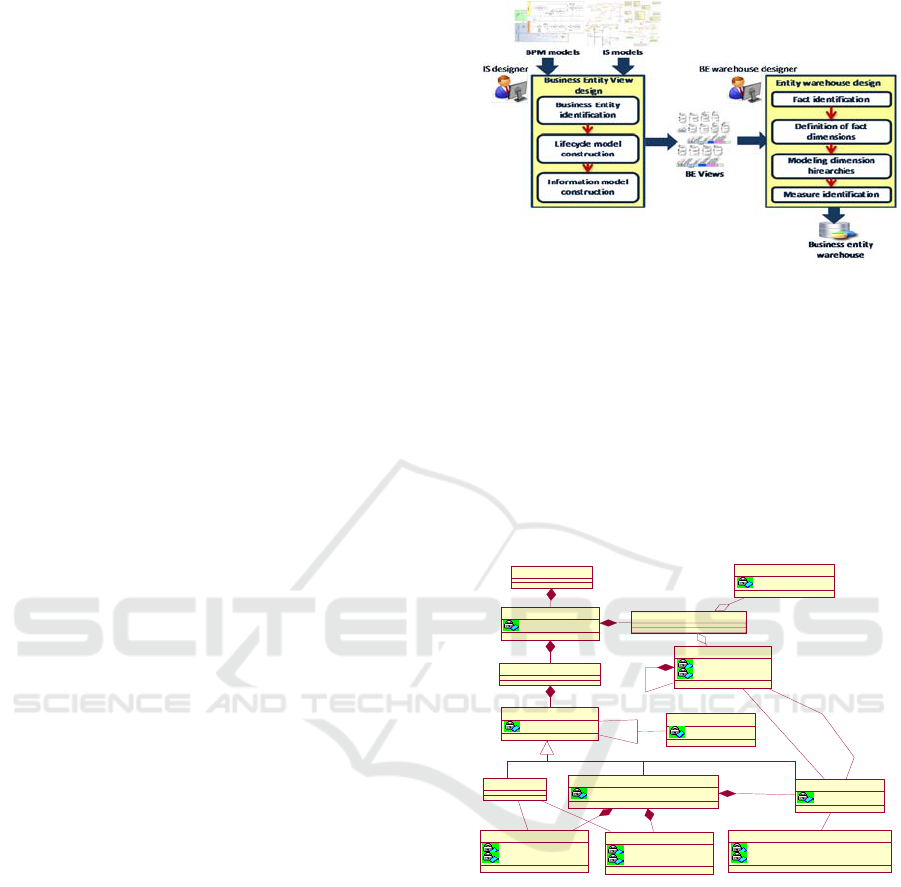
As illustrated in Figure 1, BEW our construction
method operates in two main steps: the first step
designs a view that we call the Business Entity View
(BEV); the second step designs a warehouse that
will be loaded with this view.
To represent a BE, we use the Guard-Stage-
Milestone (GSM) language (Hull et al., 2011). This
language is considered as a standard for BE
specification and modelling. Figure 2 shows the
meta-model of GSM.The information model of
GSM captures all of the business-relevant data about
a BE. It includes both data and status attributes. The
lifecycle model specifies progression stages.
3.1 Business Entity
The business entity warehouse is based on the
concept of business entity (BE). A BE is a key
business-relevant dynamic conceptual object that is
created, evolved, and archived as it passes through
the operations of an enterprise (Nandi, et al., 2010).
Indeed, a BE includes both an information model for
data about the business objects during their lifetime,
and a lifecycle model, which describes how a BE
progress over time. The lifecycle model would
include the multiple ways that the BE could be
processed. For instance, Figure 3 illustrates an
example of a BE.
Figure 1: Business entity warehouse modelling approach.
3.2 Business Entity View
A business entity view integrates IS data source
models and business process models. A BEV is
constructed based on models that usually exist since
the enterprise creation such as BPMN models and
information system models. Our BEV construction
method is composed of three steps: BE
identification, lifecycle model construction and
information model construction.
Figure 2: GSM meta-model.
As illustrated in Figure 4, the BEV construction
starts with identifying the BEs present in the process
models. Then, for each identified BE, we construct
its lifecycle model. Given a BPMN model P, we
create a top level stage of each data object state.
Since a stage can be composite, we use the sequence
of activities responsible of a state change of each
data object is used to create its embedded stages as
well as their associated tasks. Then, we create a new
milestone for each stage obtained in the new GSM
model. We also create the stage guards depending on
the direct predecessor of the corresponding activity
in the business process model P. Afterwards, we
create performers based on the pools and lanes of P
Behavior
type : String
Component
name : String
1..*
1..*
1..*
1..*
GSMModel
LifeCycleModel
1..*1..*
Business Entity
name : String
1..*1..*
StatusAttribute
name : String
Event
InformationModel
1..*1..*
MileStone
status : boolean
sentry : String
0..*
0..*
0..*
0..*
Guard
sentry : String
status : boolean
1..*
0..*
1..*
0..*
DataAttribute
name : String
type : String
1..*1..*
0..*0..*
Stage
topLevelStge : boolean
1..*1..*
1..*1..*
Performer
name : String
organisationalUnit : String
Task
type : String
0..*
0..*
+input
0..*
0..*
0..*
0..*
+output
0..*
0..*
1..*1..*
1
1..*1..*
Business Entity Warehouse: A New Design Method for Decision Support Systems from Business Entities
143
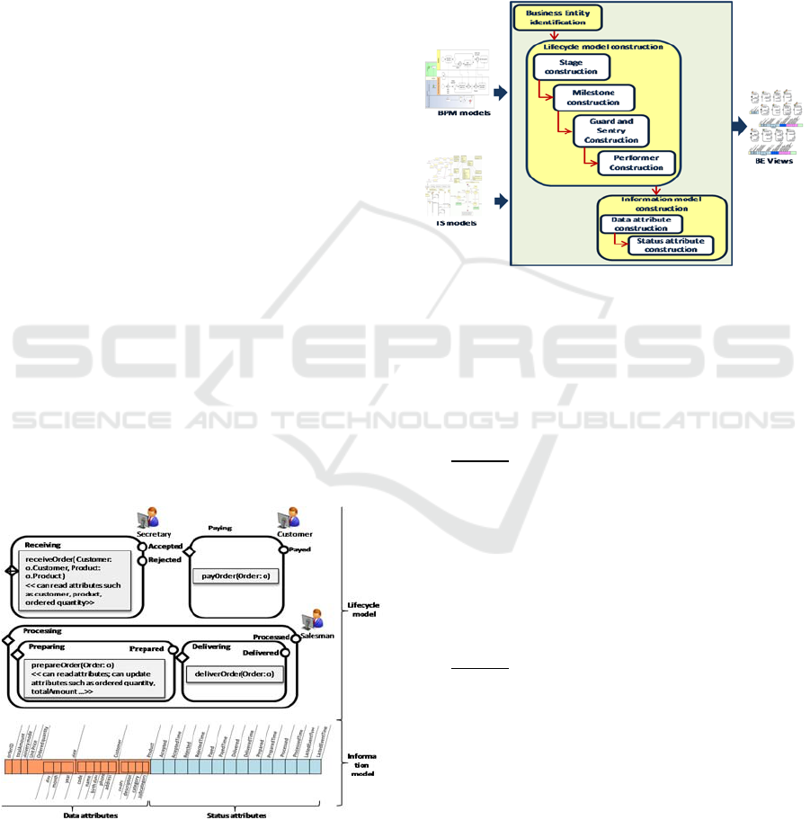
and we associated them with the corresponding
atomic stages. At the end, we construct the
information model for each identified BE from the
class diagram.
3.3 Business Entity Warehouse
A business entity warehouse is an analytical
database that stores historical data about BEs, their
business data and their business processes to meet
analytical purposes. It is composed of traditional
multidimensional concepts (facts, dimensions,
hierarchies and measures).
We use the X-DFM (Extended Dimensional Fact
Model) formalism (Mansmann et al., 2007), an
extended conceptual model of DFM (Golfarelli et
al., 1998) in order to represent our BE warehouse
model. DFM stands out for its simplicity and
expressiveness for representing the
multidimensional concepts. This model consists of a
set of fact schemes in form of graphs centred at the
facts type.DFM represents a dimension as a sub-
graph composed of dimension level attributes as
nodes (or labelled circles) and property attributes as
terminal nodes represented by labelled lines. The
“rolls-up-to” relationships between dimension level
attributes are modelled as edges. The x-DFM offers
some advanced constructs, such as fact
generalization and fact hierarchy, relevant for our
model. A fact generalization allows modelling
heterogeneous facts with a subset of common
characteristics. A fact hierarchy allows modelling
the phenomenon of interchangeability between fact
and dimension roles.
Figure 3: A GSM example: Order Entity.
4 BUSINESS ENTITY
WAREHOUSE DESIGN
To design our BEW, we start from the BEV model,
and we apply a set of rules to extract the elements of
the warehouse (facts, dimensions and measures).
First, we identify the analysis subjects (or facts),
then, for each fact we determine its analysis
perspectives and finally, we define its measures.
Figure 4: Business Entity View design.
4.1 Fact Identification
Facts represent subject analysis. As facts build the
focus of a multidimensional scheme, the first step is
concerned with identifying candidate facts in the
scheme.
Rule 1: For each transactional BE of the BEV,
we define a fact in the BEW model that has the same
name as the BE.
In the business process analysis, the major
subjects of analysis are transactional BEs because
they materialize transactional activities and therefore
contain relevant analysis data (see Business Entity
class in Figure 2). So, they are considered as facts.
For example, we map the BE Order of Figure 3 to a
fact called BE_Order.
Rule 2: For all stages in a lifecycle model of a
BE (in the BEV), we build a fact in the BEW which
name is composed of the BE name and the word
‘Stage’ as a suffix.
Since a BE gets through a set of stages during its
lifecycle(cf. Figure 2), it is also relevant to analyse
its behaviour in terms of its stages. That is why we
consider each stage as a fact. For instance, by
applying Rule 2 to our example, we obtain a fact
called Order_Stage. This fact will hold all instances
of the stages Preparing, Processing, etc.. The
analysis of the Order_Stage helps, For example, to
detect eventual delivery delays.
ICSOFT-EA 2016 - 11th International Conference on Software Engineering and Applications
144

Rule 3: For all tasks in a stage of a BE of the
BEV, we build a fact in the BEW, which name is
composed of the BE name and the word ‘Task’ as a
suffix.
Because a stage is achieved through a set of
tasks, analysing it boils down to analyse its tasks.
Indeed, tasks represent transactional activities of an
enterprise that contain relevant data to analyse (see
the composition relationship between the classes
Task and Stage in Figure 2).Thus, we consider tasks
as facts too. For instance, in our example, Rule 3
transforms all tasks of the BE Order into a single
fact called Order_Task. Analysing this fact helps, for
instance, to detect who is responsible of eventual
delivery delays.
Rule 4: For all events of a BE lifecycle of the
BEV, we build a fact in the BEW, which name is
composed of the BE name and the word ‘Event’ as a
suffix.
To analyse events and their effects on business
objects, stages and tasks, we have to take them as
facts. By applying Rule 4 to our example, we map
all event types to a fact called Order_Event(c.f.,
Figure 5).For instance, a delayed delivery start may
be explained by analysing the events that occur
within the system when BE Order is in the stage
“Processing”.
The three component types of the lifecycle
model of the BE have been modelled as separate fact
types BE_Task, BE_Stage, and BE_Event.
However, these heterogeneous classes have common
characteristics. So, we generalize them into a super-
class fact type called BE_Component (i.e.,
Order_Component in Figure 5). An important
advantage of the generalization is that we can model
the behaviour of components with respect to each
other (see Behaviour class in Figure 2).
Rule 5: For all elements of the lifecycle model of
a BE (Stage, Task and Event), we define a fact
which name is composed of the BE name and the
word “Component”.
Rule 6: For all the behavioural features of the
BE lifecycle, we define a fact called “Behaviour”.
To analyse the control flow between the lifecycle
components of a BE, it is relevant to define a fact
that holds all its instances (c.f. the fact Behaviour in
Figure 5).For example, this fact can be used to
analyse the waiting duration for the start of some
parallel tasks after the termination of a preceding
task.
4.2 Definition of Fact Dimensions
To complete our warehouse BE design, we must
identify the analysis perspectives (or dimensions) of
facts from the BEV. Since this latter is an integrated
view of a BE, it resembles all BE perspective
categories (informational, functional, behavioural
and organizational). So, it provides the ‘who’,
‘what’, ‘where’, ‘when’, ‘why’, and ‘how’ context
surrounding all the facts identified in section 4.1.
Hence, to define the dimensions of each fact, we
must examine both, the information model and the
lifecycle model. The information model is composed
of data and status attributes (see Figure 2). The data
attributes serve for identifying the dimensions of the
informational perspective of all facts. In GSM, a
data attribute type may be predefined (e.g. String,
Boolean, etc.) or defined by the user (e.g. Customer
in figure 3). So, we define dimensions characterizing
the fact BE depending on data attribute types based
on the following rules:
Rule 7: Each data attribute whose type is
predefined and not numeric corresponds to a
degenerate dimension characterizing the fact BE
with the same name as the attribute.
In a BE specification, a data attribute which
domain is a finite set of values (i.e., payment mode,
delivery means, etc.), can be significant for the
analysis. Such data attribute could be regarded as a
potential dimension with only one parameter
(degenerate dimension) and must be the subject of
an attentive examination.
Rule 8: Each data attribute whose type is
complex (i.e., defined by the user) correspond to a
dimension characterizing the fact BE with the same
name as the attribute.
An attribute of complex type in a BE completes
information about this BE and provides further
information on it. So, it represents a perspective of
the BE and answers one of the questions: ‘Where’,
‘Who’, ‘Why’, ‘How’, ‘What’ or ‘When’. Hence we
consider this attribute as a dimension.
In our running example, the BE Order includes
the data attributes date, product, customer and
delivery mode(cf. Figure 3).The application of the
rules 7 and 8 to the Order data attributes provides
the dimensions Date, Product, Customer and
delivery mode characterizing the fact Order.
A phenomenon that is important to mention here
is that fact and dimension roles are interchangeable.
For example, one can analyse the number of product
types and the duration of each stage (“Receiving”,
“Processing”, “Paying”, etc.) of the BE_Fact Order.
So the BE_Stage plays the role of a dimension for
the BE fact. Moreover, it is also important to
consider the BE as a dimension of the fact BE_Stage
that allows to analyse the stage with respect to all
Business Entity Warehouse: A New Design Method for Decision Support Systems from Business Entities
145

BE instances which were in this stage. So, it is
possible to analyse for instance the duration of each
task of the stage “Processing” for each category of
ordered products. This interchangeability of fact and
dimension is possible thanks to the integration of
data and process within the BEV.
Rule 9: For the Fact BE, we define
BE_COMPONENT (BE_Task, BE_Event and
BE_Stage) as dimension.
Stages and events give behavioural information
about the BE. They answer the “how” question of
analysing a BE with respect to its lifecycle. Hence
they play the role of a potential dimension for the
BE fact. In addition, a BE can be analysed with
respect to the functional or the organizational
perspectives by considering BE_task as dimension.
Consequently, we can, for example, analyse the time
between the occurrence of the event
“processed.achieved()” of orders and the starting of
the BE_task “payOrder” for all the BEs of a given
period of time.
Rule 10: For the fact BE_Stage, we define the
dimensions: BE, BE_Task, BE_Event, D_Guard,
D_Milestone, D_time.
The BE dimension of the BE_Stage fact answers
to analysis requests from the informational
perspective. BE_Task covers the functional and the
organizational ones. Whereas BE_Event, D_Guard,
D_Milestone and D_Time represent the behavioural
perspective. For instance, with defined BE_Stage
dimensions, we can analyse the mean time of tasks
of the stage “Processing” for the orders of a given
period.
Rule 11: For the fact BE_Event, we define four
dimensions: BE, D_Time, BE_Stage and BE_Task.
The dimensions of the BE_Event defined in Rule
11 cover the information, functional, organizational
and behavioural perspectives. Using these
dimensions, we can analyze, for example, the
number of opened stages due to the occurrence of
the event “processed.achieved()” for the orders of a
given period of time.
Rule 12: For the fact BE_Task, we define
BE,BE_Stage, BE_Event, D_Time and D_Performer
as dimensions.
The BE dimension of the BE_Task fact answers
to analysis requests from the informational
perspective. D_Performer covers the organizational
one(see Performer class in Figure 2). Whereas
BE_Event, BE_Stage and D_Time represent the
behavioural perspective. After applying Rule 12, we
can analyze the mean duration of the task “Prepare
Order” for each category of the ordered products.
Rule 13: For the fact BE_Component, we define
D_Time, BE as dimensions.
Recall that the BE_Component fact results from
the generalization of the facts BE_Stage, BE_Task
and BE_Event. Hence, its dimensions are those
obtained by the factorization of the dimensions
D_Time and BE which are common to all these
facts. Back to our example, the dimensions Order
and D_Time defined by applying Rule 13 represent
dimensions of the fact Order_Component.
Rule 14: For the Behaviour fact, we define the
dimensions Input and Output, which inherit from the
dimension BE_Component.
The generalization made through the fact
BE_Component in Rule 13 makes it possible to
model the behaviour of components with respect to
each other. Thus, we consider two dimensions, of
type BE_Component, called Input and Output of the
fact Behaviour (see Figure 5).
Table 1 shows a recap of our rules and the facts
and dimensions that they generate.
4.3 Modelling Dimension Hierarchies
In our multidimensional model, the analysis
perspectives of facts contain dimensional attributes
organized in one or more hierarchies to support
multiple granularities. To complete our BE
warehouse design, we identify, first, the attributes of
each dimension, and then we organize them into
hierarchies based on the information available in the
BEV. Hence we define the following rules.
Rule 15: The attributes of a dimension issued
from a complex data attribute or from the lifecycle
model of the BEV are all of the elements composing
this data attribute. Non-character attributes are
generally not meaningful and therefore should be
carefully examined. The atomic attributes which
provide descriptive information of the dimension are
weak attributes in the corresponding dimension.
By applying Rule 15 on our example (c.f., Figure
3),“codPr”, “subcategory” and “category” of the
complex attribute Product are transformed into
dimensional attributes of the dimension Product
while the attribute “description” is transformed into
a weak attribute within the same dimension (cf.
Figure 5).
Rule 16: Each dimension has an identifier that
represents the finest granularity in each hierarchy of
this dimension.
Rule 17: The attributes of a dimension are
semantically ordered from the most specific to the
most general one to form candidate hierarchies. The
definition of the order of attributes requires domain
knowledge.
ICSOFT-EA 2016 - 11th International Conference on Software Engineering and Applications
146

Table 1: A recap of facts and their dimensions.
Fact generation rules
R1 R5 R2 R3 R4 R6
Facts
Dimensions
BE
BE_Comp
onent
BE_Stage BE_Task
BE_Eve
nt
Behaviou
r
BE
×
Predefined data attribute
×
Complex data attribute
×
BE_Compo
nent
BE_Stage
×
× ×
output
×
BE_Task
×
BE_Event
×
Input
×
D_Guard
×
D_Milestone
×
D_Time
×
D_Performer
×
Dimension generation rules
R9 R7 R8 R13 R10 R12 R11 R14
By applying the Rules 16 and 17 to the attributes
of the dimension Product of the fact BE_Order (cf.
Figure 5), we define the hierarchy
codPr<subCategory<category. This hierarchy
supports Order analysis per product, per subcategory
and per category.
On the other hand, the Date dimension is present
in almost all facts, with well-known hierarchies. To
simplify the design process of the BEW, we suggest
the following full (standard) hierarchies that cover a
large use of the Time dimension:
H
Time1=[Id_Time<Second<Minute<Hour<Day<
Month<Quarter < Semester<Year]
H
Time2 = [Id_Time< Week]
H
Time3 = [Id_Time<Sales_Period]
Our multidimensional model is characterized by
the interchangeability of fact and dimension roles.
So, when a fact is treated as a dimension, then all its
dimensions become its hierarchies. Back to our
BEW model, business entity is treated as a fact
characterized by a set of dimensions. For instance,
the fact Order can be analysed regarding
Order_Component, Customer, Product, etc. This fact
can be drilled-down to BE_Component for a higher
level of detail. As a result, the dimensions of the fact
BE_Component are considered as hierarchies when
this latter is treated as dimension of the fact BE.
When applying Rule 18 to our example, D_Time
represents a hierarchy of the dimension
Order_Component when the Order is treated as fact.
Rule 18:.When a fact is treated as dimension,
then all of its dimensions become its hierarchies.
4.4 Measures
The last step of our BEW design is the identification
of measures for analysis subjects.
Rule 19: Each atomic data attribute which has a
numeric type and which has not been transformed to
a dimension represents a measure for the business
entity fact.
Back to our running example, the Rule 19
transforms the attributes totalAmount,
orderedQuantity and unitPrice of the BE Order (cf.
Figure 3) to measures for the fact Order of the
Figure 5. We can also derive measures by means of
aggregation functions during the query execution.
For instance, queries may investigate the runtime of
a given task, the number of occurrences of a specific
event, etc.
The resulting structure of the entire BEW
scheme in terms of facts, dimension hierarchies, and
the relationships between them is presented in
Figure 5 in the X-DFM notation. Solid arrows
represent the roll-up and drill-down relationships
while dashed arrows express the generalization
relationships.
Our BEW design approach fits within bottom-up
warehouse design approaches. So, it shares some
communalities with warehouse design works starting
from IS models (Ben-Abdallah et al, 2013)
(Hachaichi and Feki, 2013). Indeed, these works
define some Rules to extract multidimensional
elements from information system design models
(i.e., UML class diagrams) (Ben Abdallah et al.,
2013) or database schemas (Hachaichi and Feki,
2013).But they do not introduce any business
process aspects in the warehouse design, whereas
the originality of our method stems from the
integration of business process and IS data.
5 CONCLUSIONS
In this paper, we have proposed a new warehouse
Business Entity Warehouse: A New Design Method for Decision Support Systems from Business Entities
147
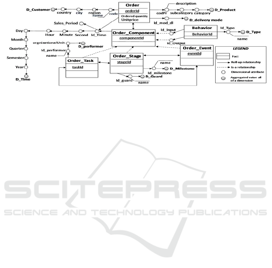
Figure 5: A BEW model for the business entity Order.
concept, the business entity warehouse (BEW). A
BEW is a database which stores historized data
about business entities, their properties and
behaviour. To design our BEW, we use a business
entity view model that offers an integrated view of
data and their manipulating processes at design time.
We extract our warehouse elements (facts,
dimensions and measures) based on a set of Rules.
First, we identify the analysis subjects, then, for each
fact we determine its analysis perspectives and
finally, we define its measures.
Unlike current business intelligence applications
and most researches on enterprise performance
analysis which focus on one part of the business in
isolation, our BEW provides an integrated basis to
analyse business data and/or business processes.
Indeed, it exploits the strong relationships between
the business data and the business processes of an
enterprise to provide analyses of the correlations
among informational, functional, behavioural and
organizational aspects of business processes.
Currently, we are finalizing the development of a
toolset supporting our approach. This tool will
provide for a means to evaluate the performance of
our method in terms of its precision in identifying all
pertinent analysable elements.
REFERENCES
Ben-Abdallah, M., Zaaboub Haddar, N., Ben-Abdallah, H.
(2013). A Business Goals Centric Method for
Automatic DW Design from UML Models. ICSOFT ,
pp. 15-23.
Bézivin, J., Jouault, F., Rosenthal, P., Valduriez, P.
(2005). Modeling in the Large and Modeling in the
Small. (U. Aßmann, M. Aksit, & A. Rensink, Éds.)
Model Driven Architecture, 3599, 33-46.
Golfarelli, M., Maio, D.,Rizzi, S. (1998). The dimensional
fact model: A conceptual model for dat warehouses.
International Journal of Cooperative Information
Systems, 7, 215-247.
Hachaichi, Y., Feki, J. (2013). An Automatic Method for
the Design of Multidimensional Schemas from Object
Oriented Databases. International Journal of
Information Technology and Decision Making,
6, 1223-1260.
Hull, R., Damaggio, E., De Masellis, R., Fournier, F.,
Gupta, M., Heath III, F. ((2011). Business Artifacts
with Guard-Stage-Milestone Lifecycles: Managing
Artifact Interactions with Conditions and Events. Conf.
on Distributed Event-Based Systems DEBS 2011, 51-62.
List, B., Schiefer, J., Tjoa, A. M., Quirchmayr, G. (1999).
The process warehouse: a data warehouse approach
for business process Management, In e-Business and
Intelligent Management. Proceedings of the
International Conference on Management of
Information and Communication Technology
(MiCT1999), Copenhagen, Denmark, 1999.
Mansmann, S., Neumuth, T., & Scholl, M. H. (2007).
Multidimensional data modeling for business process
analysis. Proceedings of 26th International
Conference on the Entity Relationship Approach
(ER’07), 4801, 23-38.
Nandi, P., König, D., Klicnik, V., Claussen, S., Moser, S.,
Kloppmann, M., et al. (2010, April). Data4BPM, Part
1: Introducing Business Entities and the Business
Entity Definition Language (BEDL).
Radeschütz, S., Schwarz, H., Niedermann, F. (2015).
Business impact analysis—a framework for a
comprehensive analysis and optimization of business
processes. Computer Science - Research and
Development , 30 (1), 69-86 .
Romero, O., Abelló, A. (2007, November 9). Automating
Multidimensional Design from Ontologies.
Proceedings of the ACM tenth international workshop
on Data warehousing and OLAP DOLAP '07 , 1-8.
Shahzad, K., Zdravkovic, J. (2012). Process warehouses in
practice: a goal-driven method for business process
analysis. Journal of Software: Evolution and Process ,
321-339.
Stefanov, V., List, B. (2007). Explaining data warehouse
data to business users - a model-based approach to
business metadata. ECIS , 2062-2073.
ICSOFT-EA 2016 - 11th International Conference on Software Engineering and Applications
148
