
IMU Acceleration Drift Compensation for Position Tracking in
Ambulatory Gait Analysis
Serhat İkizoğlu
1
, Kaan Şahin
1
, Ahmet Ataş
2
, Eyyüp Kara
2
and Tunay Çakar
1
1
Control and Automation Engineering Dept., Istanbul Technical University, Istanbul, Turkey
2
Audiology Department, Cerrahpaşa Medical School, Istanbul University, Istanbul, Turkey
Keywords: Balance Disorder, Gait Analysis, Inertial Sensors.
Abstract: This study is a part of a project where we target determining discriminative features to define diseases that
cause disorders in the human vestibular system. For this purpose we aim to analyze the gait of the person.
Among a number of parameters used for gait analysis, some make use of the foot- and knee positions.
Hence the exact determination of position is of great importance. Here we use inertial sensors (IMU) placed
on foot and knee in order to calculate the displacement by double integrating the free acceleration output
data of the sensor. Thus, the overall position accuracy is highly dependent on the accuracy of the
acceleration data where the offset and drift play great role in its corruption. We propose a method to
minimize the error due to sensor offset and drift by utilizing the fact that there are gait intervals where the
foot rests. The results are promising that the calculated average error is low; though the standard deviation
needs some further amendment.
1 INTRODUCTION
The vestibular system is one of the most important
survival skills in human life. In connection with
others the vestibular system provides the link of the
individual with the physical environment. (Hansson
et al., 2010). A weakness or an interruption in the
operation of this system would cause disruption in
spatial orientation and thus affect the connection of
the person with several fields of life such as work,
education, social life etc. (Gaerlan, 2010).
Measuring the body posture and its stability,
processing the data collected from active gait and
rest are hot topics in literature about human balance.
(Chang et al., 2012; Basta et al., 2013; Galna, 2014).
Table 1 lists some of the gait parameters that are
examined for clinical purposes in literature (Herran
et al., 2014).
Table 1: Some gait parameters observed for clinical
purposes.
Stride velocity Stride length
Step length Cadence
Step Width Traversed distance
Route Long-term monitoring of gai
t
Step time Stop duration
There are three main approaches for gait
analysis: Image processing, using floor sensors and
capture data from sensors placed on the body
(Herran et al., 2014).
The methods based on image processing
generally use cameras to record the gait and the
captured data will be processed as to filter the image
to get a black and white copy only, to count pixels
(either light ones or dark) etc. which will help to
analyze the gait (Pratheepan et al., 2009; Chang et
al., 2009)
Another popular method for gait analysis is using
floor sensors. Here usually pressure sensors are
positioned along a floor where the walk takes place.
The data acquired by the sensors will then be
processed on a digital platform to give information
about the quality of the gait (Vera-Rodriguez et al.,
2013).
Another group of methods for gait analysis
makes use of wearable sensors that are positioned on
several parts of the body (Tao et al., 2012; Abdul
Razak, 2012). Some of the popular sensors used for
this purpose are: Accelerometers, gyros,
piezoelectric/piezoresistive pressure sensors,
goniometer sensors etc.
Each sensor has its pros and cons. For example
one of the main problems with the goniometer is that
582
˙
Ikizo
˘
glu, S., ¸Sahin, K., Ata¸s, A., Kara, E. and Çakar, T.
IMU Acceleration Drift Compensation for Position Tracking in Ambulatory Gait Analysis.
DOI: 10.5220/0006422905820589
In Proceedings of the 14th International Conference on Informatics in Control, Automation and Robotics (ICINCO 2017) - Volume 1, pages 582-589
ISBN: 978-989-758-263-9
Copyright © 2017 by SCITEPRESS – Science and Technology Publications, Lda. All rights reserved

goniometers attached on the body lose their position
during the motion (Roatenberg et al., 2013). Another
remarkable problem is the alignment of the angle
measuring sensor with the joints. This problem
increases with an increase in the number of the
degree of freedom of the joint.
Around 38% of the methods used for gait
analysis are based upon inertial-sensor based
systems (Herran et al., 2014). An inertial sensor that
houses 3D accelerometers, gyroscopes and
magnetometers can provide accurate orientation data
at least for short time intervals. Gyroscopes measure
angular velocity where accelerometers provide the
acceleration vector in sensor coordinates.
Yavuzer, G. indicates that three dimensional
balance and walking analysis system is the most
important diagnosis tool to assess the integrity of
orthopedic and vestibular system. Camera based and
static systems that are integrated to hospital
environment have low mobility and high charge.
Instead, wearable sensors that help inertial
measurement will enhance the quality of the analysis
and free the patient from being in a special
environment making the outdoor data acquisition
possible (Yavuzer, 2009). Alberts, J. L. et al. studied
center of gravity computing and postural stability
where data was collected by the gyroscope inside
ipad 2 and they compared the results with Neurocom
computarized dynamic posturography. The results
obtained from dynamic posturography and ipad 2
were declared to be quite close. In accordance with
this information, the authors put forth that gyroscope
is a good means to measure center of gravity and
postural stability (Alberts et al., 2015). Tadano S.
et.al. studied wearable acceleration and location
sensors where they focused on body posture,
position and motion symmetry of body segments
such as hip, knee and ankle. The authors announced
that compared to systems capturing and processing
motion with camera, this method gave a better
qualified and real-time documentation of motion.
They concluded that acquiring angular data and
measuring motion speed with high precision is
possible with wearable sensors (Tadano et al., 2013).
The wearable sensors are usually located on feet,
ankles, knees and waist (Roatenberg et al., 2013). In
our project we are also using wearable sensors. A
close look to Table 1 puts forth that determination of
the correct position of feet is of great importance.
On the whole of the project, data collected from
motion sensors placed on the body and the insole
pressure sensors will be of interest; but this study
focuses on some vital problems faced when
acquiring data from motion sensors positioned on
certain locations on the leg only. We are mainly
interested in determining the correct position of the
foot within a limited walk-path length (11.5m).
Thus, the frame of this study is restricted with the
search for the solution to offset and drift problems of
the accelerometer data in inertial sensors to give
correct position data.
In order to describe the way we go to reach our
aim the rest of the paper is arranged as follows: In
Section 2 we first define the problem with the
acceleration data and we introduce the sensor used
in our study. Section 2 also gives explanation about
previous work and its reflection on this study. The
proposed method to obtain the correct position
information and considerations about the estimation
of the error is handled in Section 3. This section
further presents the experimental set-up and sample
graphs of uncorrected and corrected data according
to the introduced method. This section is followed
by experimental results and error calculation. Finally
we discuss conclusions drawn and give perspective
about future work.
2 CORRECTION OF THE
ORIENTATION/ POSITION
DATA
Almost all inertial sensors suffer from integration
drift. The main problem is that the position error
accumulates in time to reach a remarkable value if it
is not reset or compensated. Since the position
information is obtained by double integrating the
acceleration over time, the main source of error is
the possible wrong data to give the acceleration that
has its source in sensor noise, sensor signal offset
and/or sensor orientation error. Drift may arise from
mechanical stresses, aging, temperature changes etc.
(Tuck, 2007).
As explained before in this study we are
concentrated on minimizing the effect of the offset
and drift of the acceleration data on position
determination. In fact even the offset wouldn’t be
much harmful if it would not drift since cancellation
of a constant DC shift is not much exhausting.
In our project we use the MTW2 Wireless 3DOF
Motion Tracker from Xsens, each sensor comprised
of 3D accelerometers, 3D gyroscopes and 3D
magnetometers (xsens.com).
2.1 Brief Background
Inside an inertial sensor, orientation data is usually
IMU Acceleration Drift Compensation for Position Tracking in Ambulatory Gait Analysis
583

corrected by extended Kalman filters (Bennett et al.,
2014; Won, 2010). Nevertheless the offset and drift
of the sensor requires continuous tracking of the
error for compensation during the operation. Again
the favourite technique is the use of Kalman filter to
estimate the next value accurately by utilizing a
reliable reference. The problem is even more
complicated when handling with motion tracking of
human since there are a lot of body segments which
have to be aligned with sensors. To ease the
mathematical complexity quaternions help a lot, but
still there is hard work to do to overcome the
alignment and the error problems. The body
dimensions need to be measured to estimate joint
positions and joint measurement updates serve for
correction of uncertainties sourced from sensor noise
and movement-related errors (Roatenberg et al.,
2013).
2.2 Calibration of Accelerometer
Output
Though we are interested in the gait analysis we do
not have deep concern in full human motion for the
time being. We restrict our interest mainly with the
position of foot. Thus the correct acceleration data of
the inertial sensor is vital for us.
Various studies are focused on calibrating
accelerometer output data in literature (Bennett et
al., 2014; Lee, 2016). A conspicuos study
investigates the correction of the acceleration data of
an inertial measurement unit (IMU) via various test
beds such as optical mouse, turntable and shake
table (Kamer and Ikizoglu, 2013). Here the authors
used the collected data from the test beds to train
artificial neural networks (ANN) which would
improve the accelerometer outputs by estimating the
reference data from the actual sensor outputs. The
resulting goodness of fit was reached as high as 72%
which was significantly higher than the goodness of
fit reached with classical low-pass filters giving a
value around 61%.
In our study the x- and y-axes of two sensors of
the set are also corrected with the optical mouse
(Brand A4Tech, model X5-6AK) and a ‘Back-
propagation Levenberg – Marquardt method’ based
ANN with two hidden layers of 8 and 4 neurons
respectively is trained similar to the referenced study
with a size of 28 for the train set and 13 for the test
set. We reached a goodness of fit as 74% for a linear
displacement of 5m. Moreover the ANN results are
compared with several system identification
methods using Matlab System Identification
Toolbox 7.2.1. The results are brought together to
form Table 2.
Once having obtained these values for the
goodness of fit, we wonder whether we can increase
the accuracy in determining the position during the
walk without using complex tools to correct the
acceleration data. Here we take advantage of the fact
that the human gait has its characteristic that there
are durations where the foot is motionless; in other
words the velocity is zero. Hence, these durations
can be used to prevent the accumulation of the
position error.
Though our final aim with the project is to
discover significant features to point sources of
several balance disorders, in this study we have
limited our frame with limited gait analysis along
11.5 meters. Hence, we have got a measure to verify
the accuracy of the proposed method.
3 ALGORITHM OVERVIEW
3.1 Data Acquisition Environment
All the data is collected in Cerrahpasa Medical
School. Care is taken that environmental conditions
do not influence the inertial data. As an example,
within the sensor module free acceleration data is
constructed by referencing the magneting field of
earth via magnetometers. This conditions that in
order to preserve the reliability no source causing
magnetic field should exist nearby when collecting
data. So, data is acquired on weekends when all the
offices were closed. Furthermore we have used a flat
path to ensure zero final change in z-axis position
data at the end of the walk.
3.2 Applied Method and Error
Estimation
We decided to use the free acceleration data
provided by the manufacturer of the sensor system
since this data is expected to be compensated well
enough against certain perturbers by Kalman
updates (Roatenberg et al., 2013).
The free data references the global frame, but not
the sensor axes. Thus, for the same direction of
movement the position of the sensor on the body
doesn’t care to give similar values.
In our study for each axis we calculate the mean
of acceleration for 1 sec (between the instants 2sec
and 3sec) when resting before starting the test and
then subtract the mean from all the following
instantenous acceleration values to compensate the
acceleration offset. Now that the drift in acceleration
ICINCO 2017 - 14th International Conference on Informatics in Control, Automation and Robotics
584

Table 2: Goodness-of-fit results obtained with system identification methods.
Model Model Structure
Training set –
Goodness of
fit (%)
Test set –
Goodness
of fit (%)
Linear parametric models
ARMAX
[na(2) nb(2) nc(2) nk(1)]
()() ()( ) ()()Aq yt Bqut nk Cqet
65.80 61.75
BJ (Box-Jenkins)
[nb(4) nf(4) nc(4) nd(4) nk(1)]
() ()
() ( ) ()
() ()
Bq Cq
y
tutnket
Fq Dq
65.90 62.10
State space
[na=nb=nk=nc=nd(4)]
(1) () () ()
() () () ()
x
tAxtButKet
yt Cxt Dut et
64.95 61.20
Nonlinear models
Nonlinear ARX
[na(2) nb(2) nk(1)]
()() ()( ) ()Aq yt Bqut nk et
Nonlinear regression
( 1), ( 2), ( 1), ( 2)yt yt ut ut
63.11 57.68
Hammerstein-Wiener
[nb(2) nf(3) nk(1)]
()
() ( ) ()
()
Bq
yt ut nk et
Fq
Nonlinear estimator - 10 piece- linear estimato
r
67.48 59.84
Correlation models
[m(20) n(10)]
001
1
() () ( ) ...
()()...
()
m
n
Ayt But But T
But mT Ayt T
Ayt nT
75.63 71.71
can not be compensated easily, we bring the
approach that the velocity will be reset at every rest
of the foot to prevent the accumulation of the
position error.
Let us discuss the matter on a numerical example
where the distance is 10m. This value for the path
length is taken in order to adapt the considerations to
the widely used clinical test techniques such as the
‘Timed 25-Foot Walk (T25-FW)’ technique (Herran,
A.M. et al., 2014) where the time is measured that
elapses to walk a straight line of 7.5m distance and
the linearity of the gait during this period is
analyzed. An acceleration offset drift of a
off
=
0.05m/sec
2
causes in 10 seconds a position error of:
2
2.5
If the path taken within this time is 10m, the error
will be 25%. Observations put forth that a full step
period is around 1sec, where half of this time is the
step time and the other half the rest time of the
related foot. Hence, if the velocity offset is reset at
every foot rest, so approximately every 0.5sec that
nearly corresponds to a step time, the position error
after 10m will be: Total absolute position error (Tpe)
= (Number of steps) x (position error in each step
length); thus giving:
Tpe = 10 · a
off
·t
2
/2 = 10·0.05·0.5
2
/2 = ±0.0625m
That is the relative position error will be around:
0.0625/10 ≈ 0.63%
The above calculation assumes that the
movement is along a single global axis only. In fact
the movement direction on a flat path is the resultant
of global x- and y-axis components. Thus the
acceleration along the movement direction is
calculated as:
(1)
where
,
and
represent the accelerations
along the movement direction, global x-axis and
global y-axis respectively. The combined
uncertainty
in
can be calculated in terms
of the uncertainties of
and
as:
2
(2)
where
is the covariance between
and
.
Assuming no correlation between the uncertainties
of the variables
and
yields:
/
/
(3)
IMU Acceleration Drift Compensation for Position Tracking in Ambulatory Gait Analysis
585
Hence for the case that
approximately equals
we have
√
2
which results in 0.9%
of position error for the numerical values given
above. On the other hand for some sensors the offset
on one axis is extremely small compared with the
offset on the other one. For these cases the
movement path could be directed to the appropriate
global axis to reduce the total error.
3.3 Experimental Set-up &
Experiments Conducted
Our tests have pointed out that one of the best
locations is the front part of the foot to detect that
the foot rests. Our experimental results show that a
value around 0.15m/sec
2
for the resultant
instantenous acceleration of all the three axes for
successive 5 samples can be defined as a threshold
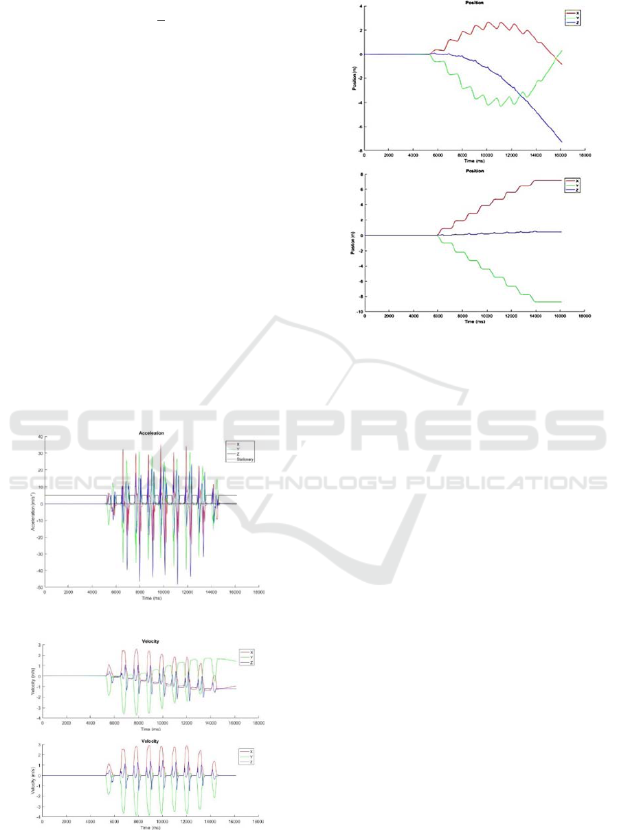
that the foot is motionless. Figure 1 pictures a
sample for free acceleration data together with the
visual information of the resting intervals of foot
that they are marked as pulses in black. The
corresponding velocity graphs for both the
uncorrected and corrected data are presented in
Figure 2. Figure 3 demonstrates the uncorrected and
corrected data for the corresponding position.
Figure 1: Sample free acceleration data.
Figure 2: Velocity data (Above: uncorrected,
below:corrected).
Figure 3: Foot position data (Above: uncorrected, below:
corrected).
For the gait/balance analysis the position and/or
direction of the foot only wouldn’t give enough
information. There is also need for information from
other parts of the body to monitor the sway of the
person. In this manner we have to know about the
movement of the knee especially while the related
foot rests. This obviously requires that the data
received from the sensor located around the knee is
reliable. On the other side for a healthy person the
knee never rests during the walk. So, the offset
correction of the sensor around the knee cannot be
performed by resetting the velocity offset at certain
intervals the same way we did it with the foot. So
there is need for another reference for correction of
the knee position information. In our study the
following recognition helped us to find a suitable
method to apply: The i
th
step length
(i>1) of a foot
is approximately the same as the difference between
the positions of the related knee corresponding to
instants when the pivot foot leaves (i-1)
st
and i
th
restings (Figure 4). This explanation holds for both
the x- and y- axis position values. So we correct the
knee position every gait cycle by resetting the
velocity offset according to the recognition
explained above. Figure 5 describes the flow
diagram for position-data correction of the knee.
ICINCO 2017 - 14th International Conference on Informatics in Control, Automation and Robotics
586
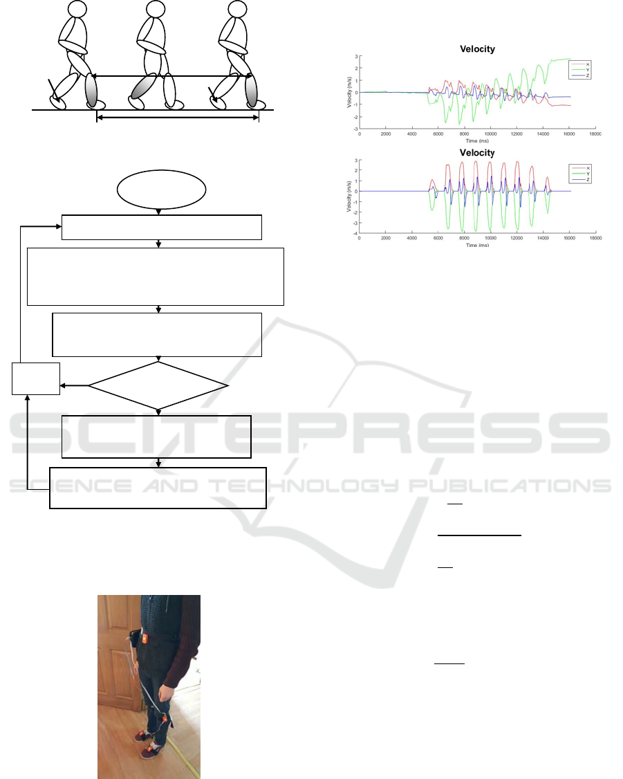
Figure 4: References to correct knee position data.
Figure 5: Flow diagram for position-data correction of the
knee.
Figure 6 shows the locations of inertial sensors
on the body.
Figure 6: Sensor locations on the body.
Figure 7 & 8 picture a sample uncorrected and
corrected velocity and position graphs -together with
the corrected position graph of the pivot foot-
respectively.
Figure 7: Knee velocity graphs (Above: uncorrected,
below: corrected).
4 EXPERIMENTAL RESULTS
AND COMMENTS
We collected data from 42 people with 33 being
healthy and 9 suffering from several problems to
cause balance disorder. The mean (
̅
) and the
standard deviation (
) of the measurements of the
path length via the sensors is calculated as 11.41m
and 36cm respectively using the formulae
̅
1
42
(4)
1
41
̅
(5)
Hence the average relative error of the length
measurement is calculated as:
̅
0.8%
(6)
where the true length is
11.5 .
The average error is acceptable; but the standard
deviation is a little large. We bring the following
comments on the results:
(i-1)
st
i
th
Yes
No
Calculateanoffsetvelocityfrom
Δp
i
=Δt∙v
off
(i‐1)
st
Determinetheinstantst
i‐1
andt
i
Determinethepositionsofthefoot(p
f
)and
theknee(p
k
)ofthesamelegatt
i‐1
andt
i
with
Δt=t
i
‐t
i‐1
Calculatethedifferenceofthefoot‐
andkneepositionsatt
i
asΔp
i
IsΔp
i
=0?
Correctthepositiondataforthetime
intervalt
i‐1
...t
i
accordingly
İ=i+1
Start
IMU Acceleration Drift Compensation for Position Tracking in Ambulatory Gait Analysis
587
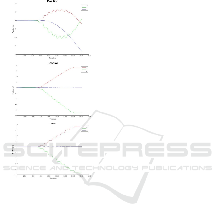
Figure 8: Knee position (Above: uncorrected, mid:
corrected) & pivot foot position graphs.
Comparing the results with those achieved by the
methods used for acceleration data correction points
that the proposed method gives much higher
accuracy than optical mouse- or system
identification based methods. This is obviously
because we reference the ground connection of the
foot where the velocity is zero; thus, having a
reference to refer to ‘frequently enough’ to avoid
accumulation of the error is more effective than
relying on calibration for long-term operation.
Besides the drift in acceleration offset following
points are also worth to mention to influence the
error and the standard deviation in the
measurements:
‐ Error in determination of the resting period of the
foot and accordingly filtering the acceleration
data.
‐ Error in observing the start and stop points of the
walk.
‐ Error in calculating the acceleration offset prior
to starting the walk that is subtracted from all the
instantenous acceleration data.
In our study the sampling rate of the sensors was
100Hz limited by the specifications of the sensor.
Increasing this frequency would obviously help for
higher accuracy that the offset at the beginning and
the resting durations of the foot can be determined
more precisely.
5 CONCLUSIONS AND FUTURE
WORK
This study is a part of the project where we aim to
discover features decribing several sources of
balance disorders. In this manner we are interested
in certain parameters used for gait analysis such as
the change of the difference between the feet
positions, step length, sway of the legs etc. These
parameters condition the correct determination of
foot- and knee positions. In our study we use inertial
sensors placed on foot and knee and the position is
determined by double integrating the free
acceleration data of the related sensor. Since the
offset and the drift of the sensor is significantly
effective on position determination we propose a
method to minimize this effect that we make use of
the durations where the foot rests. The results put
forth that the proposed method is a satisfactory
solution giving reasonable relative error in average;
nevertheless the standard deviation still needs some
correction.
So far we have applied our method mainly on
healthy people (33 out of 42) where the walk path
was a straight line. So as future work, first of all we
consider to increase the number of subjects suffering
from several balance disorders and draw a curved
path in order to verify the general applicability of the
method. Besides that we plan to develop methods to
reduce the standard deviation. In this context we
care determining the offset at the beginning more
precisely, because it influences all the durations
where movement exists. Considering the overall
frame of the project we also need to detect the sway
of the upper part of the body. So we will investigate
for methods to monitor the whole body within
acceptable error limits.
ICINCO 2017 - 14th International Conference on Informatics in Control, Automation and Robotics
588

ACKNOWLEDGMENT
This research is a part of the project ‘Development
of a dynamic vestibular system analysis algorithm &
Design of a balance monitoring instrument‘ (ID:
115E258) supported by the Scientific &
Technological Research Council of Turkey
(TUBITAK).
REFERENCES
Abdul Razak, A.H., Zayegh, A., Begg, R.K. and Wahab,
Y., 2012. Foot plantar pressure measurement system:
A review. Sensors 2012, 12, 9884–9912.
Alberts, J. L., Hirsch, J. R., Koop, M. M., Schindler, D.
D., Kana, D. E., Linder, S. M., … Thota, A. K., 2015.
Using accelerometer and gyroscopic measures to
quantify postural stability. Journal of Athletic
Training, 50(6), 578–588.
http://doi.org/10.4085/1062-6050-50.2.01.
Basta, D., Izquierdo, M. R., Varela, A. S., Ernst, A. 2013.
Mobile Posturography: Posturographic Analysis of
Daily life Mobility. Otology & Neurotology,
34:282Y291 _ 2013. Otology & Neurotology, Inc.
Bennett, T.R., Jafari, R. and Gans N., 2014. Motion Based
Acceleration Correction for Improved Sensor
Orientation Estimates. 11th International Conference
on Wearable and Implantable Body Sensor Networks.
Chang, K.M., Chen, S.H., Lee, H.Y., Ching, C.T.S. and
Huang, C.L., 2012. A Wireless Accelerometer-Based
Body Posture Stability Detection System and Its
Application for Meditation Practitioners.
Doi:10.3390/s121217620 sensors ISSN 1424-8220
www.mdpi.com/journal/sensors Article.
Chang, P.C., Tien, M.C., Wu, J.L. and Hu, C.S., 2009.
Real-Time Gender Classification from Human Gait for
Arbitrary View Angles. Proceedings of 2009 11th
IEEE International Symposium on Multimedia, San
Diego, CA, USA, 14–16 December 2009; pp. 88–95.
Gaerlan, M. G., 2010. The role of visual vestibular and
somatosensory systems in postural Balance. UNLV
Theses/Dissertations/Professional Papers/Capstones,
Paper 357.
Galna, B., Barry, G., Jackson, D., Mhiripiri, D., Olivier,
P., Rochester, L., 2014. Accuracy of the Microsoft
Kinect sensor for measuring movement in people with
Parkinson's disease. Gait & Posture, Elsevier.
Hansson, E.E., Beckman, A., Håkansson, A., 2010. Effect
of vision, proprioception, and the position of the
vestibular organ on postural sway. Acta Oto-
laryngologica, 130 (12), 1358-63.
Herran, A.M., Zapirain, B.G. and Zorrilla, A.M., 2014.
Gait Analysis Methods: An Overview of Wearable and
Non-Wearable Systems, Highlighting Clinical
Applications. Sensors ISSN 1424–8220
www.mdpi.com/journal/sensors.
Kamer, Y., Ikizoglu, S., 2013. Effective accelerometer test
beds for output enhancement of an inertial navigation
system. Measurement, Vol. 46, No. 5, 06/2013, s.
1641-1649. Elsevier.
Lee, C.G., Dao, N.N., Jang, S., Kim, D., Kim, Y., and
Cho, S., 2016. Gyro Drift Correction for An Indirect
Kalman Filter Based Sensor Fusion Driver. Sensors
article.
Pratheepan, Y., Condell, J.V. and Prasad, G., 2009. The
Use of Dynamic and Static Characteristics of Gait for
Individual Identification. Proceedings of 13th
International Machine Vision and Image Processing
Conference, Dublin, Ireland, pp. 111–116.
Roatenberg, D., Luinge, H. and Slycke, P., 2013. Xsens
MVN: Full 6DOF Human Motion Tracking Using
Miniature Inertial Sensors. XSENS TECHNOLOGIES.
Tadano, S., Takeda, R. and Miyagawa, H., 2013. Three
dimensional gait analysis using wearable acceleration
and gyro sensors based on quaternion calculations.
Sensors (Basel, Switzerland), 13(7), 9321–9343.
http://doi.org/10.3390/s130709321.
Tao, W., Liu, T., Zheng, R. and Feng, H., 2012. Gait
analysis using wearable sensors. Sensors 2012, 12,
2255–2283.
Tuck, K., 2007. Implementing Auto-Zero Calibration
Technique for Accelerometers. AN3447
Accelerometer Systems and Applications Engineering.
Tempe, AZ.
Vera-Rodriguez, R., Mason, J.S.D., Fierrez, J. and Ortega-
Garcia, J., 2013. Comparative analysis and fusion of
spatiotemporal information for footstep
recognition. IEEE Trans. Pattern Anal. Mach.
Intell. 2013, 35, 823–834.
Yavuzer, G., 2009. Three-dimensional quantitative gait
analysis. Acta Orthop Traumatol Turc, 43(2), 94–101.
http://doi.org/10.3944/AOTT.2009.094.
Xsens website: https://www.xsens.com/products/mtw-
awinda/
Won, S.H., Melek, W.W., Golnaraghi, F. et al., 2010. A
kalman/particle filter-based position and orientation
estimation method using a position sensor/inertial
measurement unit hybrid system. Industrial
Electronics, IEEE Transactions on, vol. 57, no. 5, pp.
1787–1798.
IMU Acceleration Drift Compensation for Position Tracking in Ambulatory Gait Analysis
589
