
A New Switched Beam Smart Antenna Model for Extending Inet
Omnet++ Framework
Vincenzo Inzillo
1
, Floriano De Rango
1
and Alfonso Ariza Quintana
2
1
Dimes, University of Calabria, Via P. Bucci, Rende (CS), Italy
2
University of Malaga, Av. De Cervantes, Malaga, Spain
Keywords: Smart Antenna Systems, Switched Beam, Phased Array, Omnet++, Inet, IEEE 802.11.
Abstract: Smart Antenna Systems (SAS) are providing a strong increasing impact in digital wireless communication
systems. Due to their great advantages regarding nodes power saving and coverage enhancing, SAS are
largely employed on pervasive network environments such as MANET. Because almost the whole of exist-
ing network simulators use omnidirectional antennas on nodes, we propose a new version of Inet framework
of Omnet++ that extends its operation also for network scenarios in which nodes are equipped with direc-
tional antennas. Furthermore, we created a new directional antenna module that simulates the behaviour of a
Phased Array System and a very simple algorithm for power management in channel. The new proposed
model presents some modifications to key-modules that are involved in a normal wireless communication
scenario, in order to support asymmetrical communications between nodes.
1 INTRODUCTION
Since the early days of wireless communications,
focusing on physical layer of a network node there
are two main kinds of antenna that can be used for
equipping it in order to produce a certain behaviour
on transmission/reception: omnidirectional antennas,
which radiates and receives equally in all directions,
and directional antennas which are capable to radiate
in a fixed particular angular direction. Omnidirec-
tional strategies directly and adversely impact spec-
tral efficiency, limiting frequency reuse (Chu, 1948).
These limitations force system designers and net-
work planners to devise increasingly sophisticated
and costly remedies. In recent years, the limitations
of broadcast antenna technology on the quality, ca-
pacity, and coverage of wireless systems have
prompted an evolution in the fundamental design
and role of the antenna in a wireless system. In low
power design systems, such as Manet or Sensor
Networks, using an omnidirectional approach it is a
difficult and inconvenient way to produce efficient
systems, because the high amount of power con-
sumption of network nodes (Khuzhali, 2014), that
could be translated in overcome phenomena such as
low battery lifetime and interference generations. A
single antenna can also be constructed to have cer-
tain fixed preferential transmission and reception
directions in order to maximize its energy consump-
tion in a particular direction saving power in other
directions (Nasipuri-Sappidi, 2002). Using direc-
tional antenna there could be several advantages, in
terms of reduction of reception packet delay or per-
formance enhancing of a routing protocol (Dimitrou-
Kalis, 2004). In conventional wireless communica-
tions, a single antenna is used at the source, and an-
other single antenna is used at the destination. This
is called SISO (Single Input, Single Output) (Sen-
gar-Rani-Singhal-Sharma-Verma-Singh, 2014). In
later years, it has developed the concept of Smart
Antenna Systems intended as a particular System
that is capable to be “intelligent” basing on physical
and logical implementation features. This kind of
systems can increase the coverage area and the ca-
pacity of a wireless communication system. The
coverage area, is simply the area in which communi-
cation between a mobile and the base station is pos-
sible. The capacity is a measure of the number of
users a system can support in a given area. The em-
ployment of SAS in wireless mobile environments
allows a more efficient medium utilization with re-
spect to the classical Omnidirectional approach. For
example, Spatial Division Multiple Access (SDMA)
seeks to increase the capacity of a system. General-
ly, Smart Antennas fall into three major categories:
SIMO (Single Input, Multiple Output), MISO (Mul-
tiple Input, Single Output), and MIMO (Multiple
Inzillo, V., Rango, F. and Quintana, A.
A New Switched Beam Smart Antenna Model for Extending Inet Omnet++ Framework.
DOI: 10.5220/0006439602630271
In Proceedings of the 7th International Conference on Simulation and Modeling Methodologies, Technologies and Applications (SIMULTECH 2017), pages 263-271
ISBN: 978-989-758-265-3
Copyright © 2017 by SCITEPRESS – Science and Technology Publications, Lda. All rights reserved
263
Input, Multiple Output). In SIMO technology, one
antenna is used at the source, and two or more an-
tennas are used at the destination. In MISO technol-
ogy, two or more antennas are used at the source,
and one antenna is used at the destination. In MIMO
technology, multiple antennas are employed at both
the source and the destination. A Smart Antenna
System combines generally an antenna array with a
digital signal-processing capability to transmit and
receive in an adaptive, spatially sensitive manner. In
other words, such a system can automatically change
the directionality of its radiation patterns in response
to its signal environment. This can dramatically in-
crease the performance characteristics (such as ca-
pacity) of a wireless system. One of the most critical
aspect in wireless communications environments is
represented by the fact of using an adequate network
simulator that is able to well emulate and reproduce
an appropriate real scenario. Unfortunately, most of
the existing network simulators do not provide any
support for directional and asymmetrical communi-
cations and thus also for SAS technology. For this
reason, in the present work we propose a model that
extends the functionalities of Omnet++ simulator in
order to provide a useful support for asymmetrical
communications and Smart Antenna Systems. The
paper is structured as follows: section 2 introduces
SAS main principles; section 3 is an overview about
existing network simulator compared to Omnet++.
In sections 4 and 5, the proposed model and the pro-
posed algorithm are presented respectively. Finally,
in section 6 simulation results are discussed.
2 SMART ANTENNA
SYSTEMS (SAS)
As mentioned, SAS are intelligent systems that al-
lows a good SDMA processing (Wei, 2004); exam-
ples of SAS are: digital beamforming systems, adap-
tive antenna systems, phased array and others. Smart
antennas are customarily categorized, however, as
either switched beam or adaptive array systems.
There could be a distinction between the two major
categories of smart antennas in term of the operation
mode (Kulkarni-Bhavani, 2014); (Balanis-Ioannides,
2007):
• switched beam: a finite number of fixed, prede-
fined patterns or combining strategies
• adaptive array: an infinite number of patterns
(scenario-based) that are adjusted in real time
So, these strategies differ between beamforming
building technology. Switched beam antenna sys-
tems form multiple fixed beams with high sensitivity
in particular directions. These antenna systems de-
tect signal strength, choose from one of several pre-
determined, fixed beams, and switch from one beam
to another as the mobile moves throughout an area.
So, they produce a static fixed beam that could be
electronically controlled. Adaptive antenna technol-
ogy, instead, uses adaptive algorithm because of its
ability to effectively locate and track various types
of signals to dynamically minimize interference and
maximize the intended signal reception. In this case,
produced beam is variable and adapt itself depend-
ing on transmission channel conditions and a weight
array that dynamically varies in time. In this context,
the spatial structure is used to estimate the direction
of arrivals (DOAs) or AOA (Angle of Arrive) by
nodes. However, both systems attempt to increase
gain according to the location of the user; We can
synthetize the operating Smart Antennas principle
with the following figure (Wei, 2004):
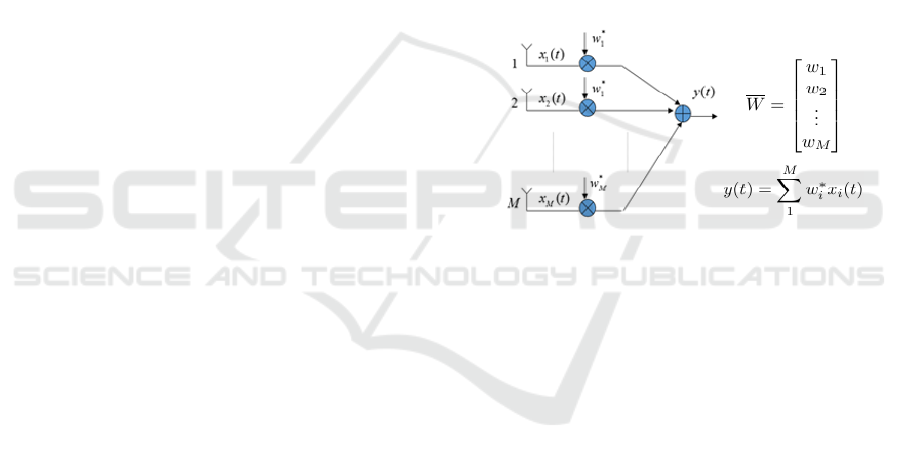
Figure 1: Smart Antenna general operation schema.
Inputs x
1
……x
M
are combined each one with el-
ement values of a weight array that varies according
to an adaptive algorithm (for example LMS or
CMA), so output y(t) is a variable beam in adaptive
array systems. Using a switched beam approach
there is no adaptive algorithm execution and weight
array can be considered missing or constant, beam is
fixed but it is very simple to realize with worse per-
formance than adaptive array systems of course.
3 NETWORK SIMULATORS
OVERVIEW AND OMNET++
There are several network simulators (Chirstu-
Namrata-John-Shibin, 2013) that could be used for
creating a network mobile scenario containing nodes
that are equipped with a particular kind of antenna
system; some of the most used software are: Ns2,
Ns3, Opnet, Omnet++. Ns2 (Charbonneau, 2010)
follows two levels of hierarchy namely C++ Hierar-
chy and the interpreted OTcL, which is one to one
correspondence. Two languages are linked to
SIMULTECH 2017 - 7th International Conference on Simulation and Modeling Methodologies, Technologies and Applications
264
achieve a higher efficiency. Ns3 (NS-3, 2014) is a
discreet-event simulator primarily targeted for re-
search and educational purposes. Ns3 is not an ex-
tension of Ns2; the similarity between Ns2 and Ns3
are both written in C++ Codes but Ns3 does not sup-
port Ns2 API. Ns3 simulator is written in C++ and
python. OPNET (Dunaytsev, 2012) is another net-
work simulator, which provides a better User Inter-
face than Ns2 and Ns3. Omnet++ (Omnet++ User
Manual, 2016) is a discrete event simulation envi-
ronment. Omnet++ provides component architecture
for models. Components (modules) are programmed
in C++, and then assembled into larger components
and models using a high-level language (NED). Re-
usability of models comes for free. Logical behavior
of modules is generally written in .cc and .h files
containing all logical functions. Because its simply
features, and because this simulator enhanced and
improved during years with some users contribution,
therefore considering that it is extremely intuitive
from user interface point of view we choose to use
Omnet++ 4.6 for our test simulations. For our pur-
pose, we used Inet framework that provides a very
complete modules and protocols choice especially
for Mobile Networks. Unfortunately, Omnet++ does
not support asymmetrical communication between
nodes (Uribe-Maureira-Dalle, 2010), so we need to
modify some logical modules configuration in order
to achieve our purpose. In this way, we would ex-
tend Inet framework in order to make it able to work
with directional antennas equipped nodes, and so for
smart antenna systems. We used a different ap-
proach with respect to (Uribe-Maureira-Dalle, 2010)
in which a Neighbors Graph Algorithm is created
for power management therefore modifying chan-
nelControl module (no longer available in current
version of Omnet++). In (Uribe-Maureira-Dalle,
2010) For supporting directional communications
between nodes, a DirectionalRadio module is creat-
ed for obtaining a directional antenna pattern; in our
work, instead, we created a new directional antenna
model and next a simple algorithm for power man-
agement that allows a “not static” assignment of
nodes power. Furthermore, the version of Omnet++
used in this work deeply differs from 4.2 version
used in (Uribe-Maureira-Dalle, 2010).
4 PROPOSED MODEL
Our model is based on the simplest SAS technology
that is the Switched Beam approach. Differently
from (Inzillo-De Rango, 2016) in which a MAC
layer analysis is accomplished, this work provides
for modifications on physical layer only. Firstly, we
created a new directional antenna module called
“PhasedArray”. This module, like other models,
extends AntennaBase module. It was created based
on Antenna Array theory, implementing in com-
puteGain function the following formula (Patel,
2007):
G(θ,φ)
TOT
= G(θ,φ)
EF
*G(θ,φ)
AF
(1)
Where the first term is referred to element factor
gain, and the second term is the array factor gain.
Array factor is the main term conditioning System
Array behavior, and its module could be expressed
as follows (Orfanidis), for linear uniform arrays:
sin / 2
AF
Nsin / 2
N
(2)
Where:
0
(cos cos )kd
(3)
k is the wavenumber, d is the distance between each
radiating elements and φ
0
is the steering angle, that
is the angle corresponding to maximum directive
gain of radiation pattern depending on radiating el-
ements number (N) too. We suppose that all ele-
ments produce the same pattern and we choose an
element factor EF = cos θ. Because Omnet++ is not
able to produce radiation pattern figure for antenna
modules, we produce a simple matlab code imple-
menting above expressions. For instance, for N=10,
φ
0
= 120°, f = 1 MHz, d = 0.5λ we have the follow-
ing situation:
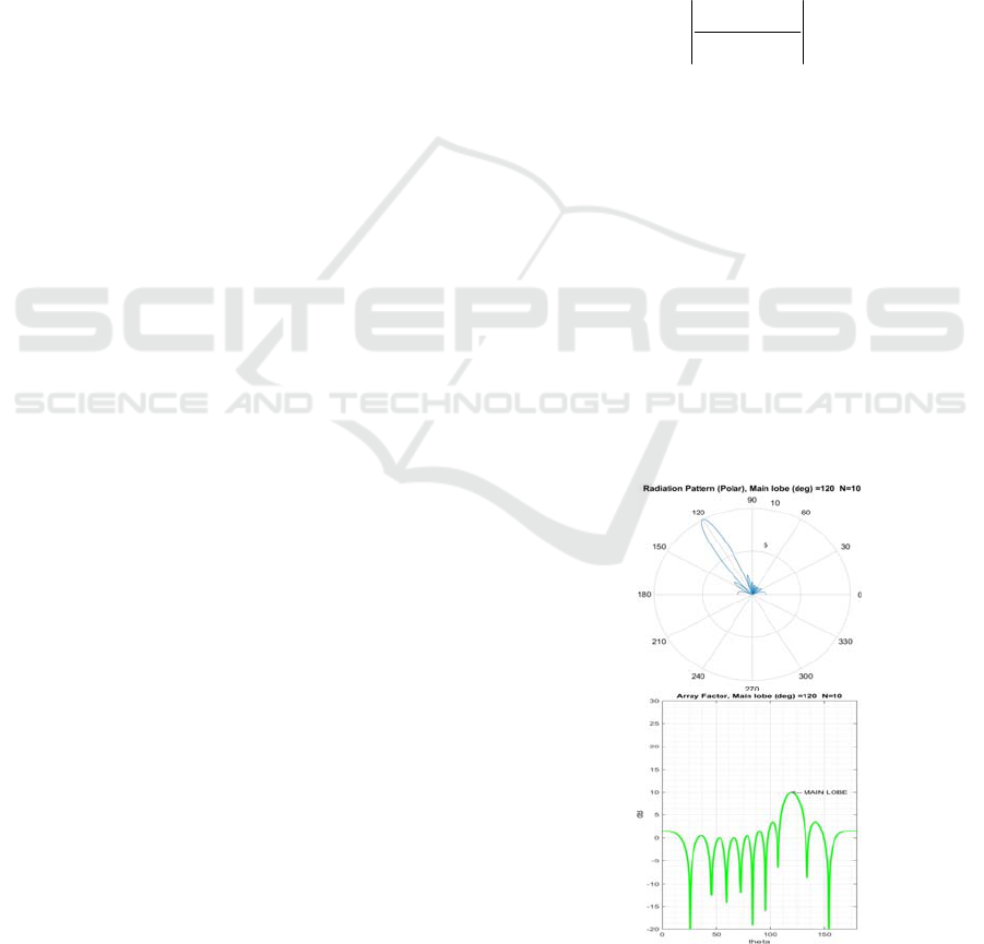
Figure 2: Array Factor plots for N=10, φ
0
= 120°, d =
0.5λ: (a) polar plot; (b) rectangular plot.
A New Switched Beam Smart Antenna Model for Extending Inet Omnet++ Framework
265
Where φ
0
varies from -180° to 180°. Fig. 2(a)
represents an example of Array Factor polar gain,
with main lobes pointed to steering angle absolute
value. Fig. 2(b) represents Array Factor rectangular
plot of the whole Phased Array system.
5 MODIFICATIONS ON INET
AND PROPOSED ALGORITHM
We created a new macro network module called
AODVNetwork2 that simulates a scenario for MA-
NET. Of course, no smart antenna submodule exists
in Omnet++ and for this purpose we modified these
existing modules in order to support asymmetrical
communications too. Primarily, we modified the
module related to mobile network nodes, so we used
an array of StandardHost called host having a size
equal to the number of nodes involved in our simula-
tions. On physical layer, we modified the Sca-
larAnalogModelBase Class that implements Free
Space Model Path Loss for propagation and we cre-
ated and inserted an algorithm in this class for node
power management in order to create a dynamic
power quantity assignment based on transmission
direction and angular position of each node. It is
recalled that Omnet++ does not support asymmetric
communication between nodes, so by default, for
each node the power value is the same for all direc-
tions. We modified computeReceptionPower func-
tion in order to implement Free Space PathLoss
Model that satisfies the relation:
P
rx
=
P
tx
G
tx
G
rx
L
Path
(4)
Given a transmitter node A and a receiver B, if A
transmits with a steering angle φ
0
towards B, B will
receive with an angle φ’ = (φ
0 -
180°) if φ
0
≥ 0 or φ’ =
(φ
0 +
180°) if φ
0
< 0; So, receiver node B, in this case,
gets an estimation of AOA based on transmission
direction of A, and adjusts its beam in order to max-
imize its reception power:
Figure 3: AOA estimation principle.
Next, we created an algorithm for dynamic as-
signment power for each host based on the main
beam direction and so on transmission/reception
direction position coordinates of nodes. For a given
node that produces a radiation pattern forming a
beam with main lobe angle φ
0
it will transmit/receive
with a power value that will be the maximum or a
fraction of this according to radiation pattern form.
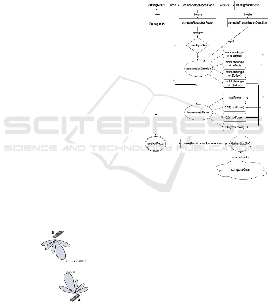
Figure 4: Logical block schema 1.
The proposed algorithm takes into account also
of the sidelobes amplitude of the pattern, so it has
implemented a classification level of side lobes
based on transmission/reception direction angle val-
ue. In Fig. 4 it is shown a logical block schema that
illustrates the main steps and modules about modifi-
cations accomplished on implementation level basis:
Rectangle forms contain modules or class names;
rounded rectangles contain class functions names or
variables names; elliptics contain only output varia-
bles names; double rounded elliptics contain only
output variables of a key function, and it can be con-
sidered as a final state of an automata. In Fig.4 we
note that ScalarAnalogModelBase extends and so
implements all functions of AnalogModelBase
Class. In ScalarAnalogModelBase there is a function
computeReceptionPower that assigns the power val-
SIMULTECH 2017 - 7th International Conference on Simulation and Modeling Methodologies, Technologies and Applications
266
ue to nodes, basing on angle position direction of a
receiver node with respect to a transmitter node; so,
it makes a test comparing main beam angle to
transmissionDirection value that is the return value
of computeTransmissionDirection function invoked
in AnalogModelBase Class. The test is carried out by
a power Algorithm that assigns a power value de-
pending on transmissionDirection value. The fol-
lowing pseudo-code better illustrates the Algo-
rithm’s operations:
Figure 5: Power Algorithm Pseudo-Code.
An important parameter for the algorithm is the
offset variable. This value is function of two parame-
ters: the mainLobeAngle (commonly referred to φ
0
)
and the spreading factor. The first term, as already
mentioned, represents the angle of maximum radia-
tion, and its value is returned by the getPhizero
function implemented in the PhasedArray module.
The second term varies from -1.5 to 2 according to
the number of radiating elements of the array. In
particular, the larger is the number of elements, the
greater is the spreading factor value. This feature
allows to take into account of the spreading effect
that affects the overall pattern varying the number of
elements. Setting an appropriate offset helps to en-
hance the sidelobes research within the beam and
their classification process. From Fig. 5 it can be
observed that, based on the transmissionDirection
value, the power is fractioned opportunely. If the
transmissionDirection value is not related to any
sidelobe level, the power is reduced to 0. This algo-
rithm is static and approximated, but more flexible,
in fact it also takes into count main beam pattern,
that is a function of elements number antenna array.
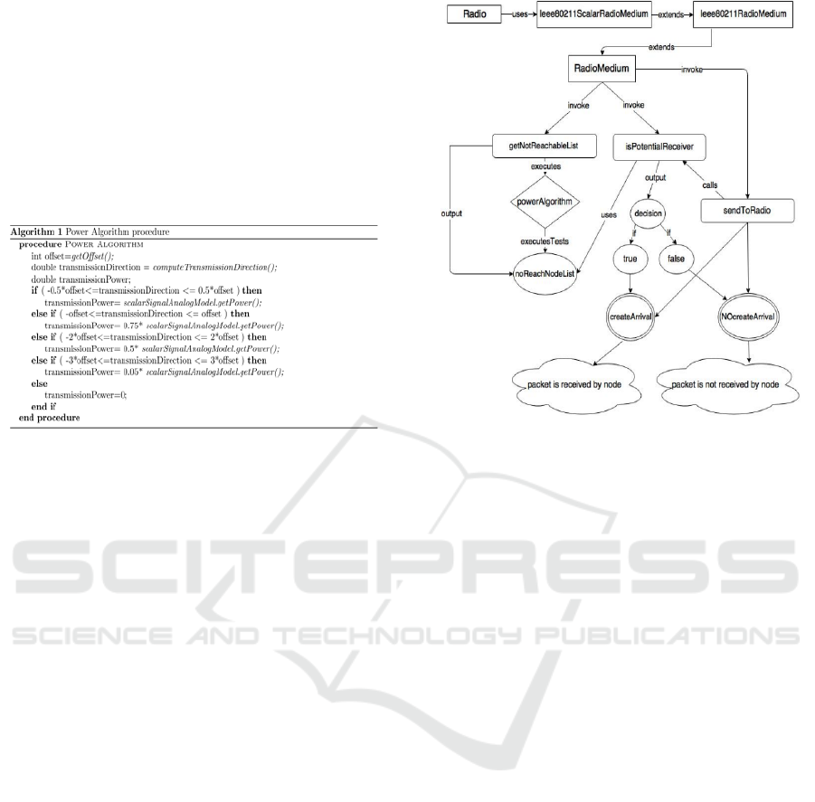
Some modifications are accomplished in RadioMe-
dium module, so we show another logical block
schema that synthetizes all functions and modules
that are involved in:
Figue 6: Logical block schema 2.
RadioMedium class, contains a remarkable num-
ber of functions that drives control of traffic flows
passing through the network. We created a get-
NotReachableList function that executes powerAlgo-
rithm and returns the complete list of nodes that
cannot be reached by a transmission due to their
current position with respect to transmitter position.
isPotentialReceiver function uses this list for deter-
mining if a given receiver is reachable or not by a
transmission, and gives a Boolean output according
to the content of list returned by getNotReachable-
List function.
6 MODEL VALIDATION AND
SIMULATION RESULTS
For validation of the designed model we chose to
consider a configuration containing only 10 mobile
nodes, and successively extend our model to config-
urations with an increasing nodes number. Due to
space limitations, we will show and discuss only
results relative to 10 nodes configuration. The fol-
lowing table synthesizes main simulations parame-
ters of this configuration; these parameters are ex-
tracted from .ini file and may be modified for every
need:
A New Switched Beam Smart Antenna Model for Extending Inet Omnet++ Framework
267
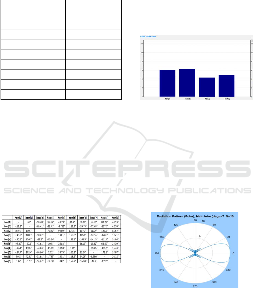
Table 1: Setting of parameters used in simulations.
Manet Routing protocol
AODV
Antenna Type
Phased Array
Antenna Freq.
1 MHz
Distance
0.5 λ
Number of Elements
10
Number of Nodes
10
Main Beam Angle (Phizero)
7°(rc1),102°(rc2)
ConFig. Mobility Static
Simulation Area Size 500 x 500 m
Simulation Time 300 s
As we can observe, distance between each radiat-
ing element is a good set for avoiding Grating Lobes
in radiation pattern; position of each node is ran-
domly generated by Omnet++; for simplicity, only
host 7 generates UDP traffic and sends it to host
0,1,3,5 that are receiver nodes. Because results de-
pend on angular position and so on transmission
direction of each node with respect to each other,
firstly we created an utility module Mempos, to take
into account the current position of the node and for
generating a matrix that maintains the current posi-
tion angle between all nodes, that is useful for eval-
uating simulations results. As follows, we show the
so called “transmission directions matrix” generated
from Mempos module. It will be very helpful for
results analysis:
Figure 7: Transmission directions matrix.
Fig. 7 shows the current transmission direction
angle of an i-row host row with respect to each other
j-column host of the network. Note that angle value
varies from -180° to 180°. For example, if host 0
sends toward host 1 it transmits with an angle of 68°
because its angular position with respect host 1. In
our simulations, we suppose that host 7 is the only
node that generates any traffic data towards receiv-
ers. For understating if the proposed antenna model
is well designed we have to compare simulations
results with a “default” configuration of AODV
model example of Omnet++ in which mobile nodes
are equipped with omnidirectional antennas. As fol-
lows it is shown the result related to the received
packets when mobile nodes use IsotropicAntenna
model:
Figure 8: Received Packets Omnet++ Omni Configura-
tion.
From Fig. 8 we can note that all nodes (on re-
ceiver side) receive packets. In particular, the overall
received traffic is uniformly distributed among
nodes. Now, we can replace the default antenna
model with our PhasedArray model. We created 2
run configurations. The first one (rc1) has main lobe
angle pointed to 7°, so, referring to our transmission
directions matrix, we can expect that generated traf-
fic will be driven towards nodes lying on main lobe
region. In particular, among all receivers, only host 3
is situated in main lobe region. Radiation pattern for
Phased array with main beam angle of 7° is shown
below:
Figure 9: Array Factor Polar Plot for N=10, φ
0
= 7°, d =
0.5λ.
In Fig. 9 we can observe that sidelobes amplitude
is very smaller than main lobe. Because the main
lobe degree value is very small, in this case the beam
is flattened close to 0. The following figure shows
received successful packets statistic referring to all
receiver nodes:
SIMULTECH 2017 - 7th International Conference on Simulation and Modeling Methodologies, Technologies and Applications
268
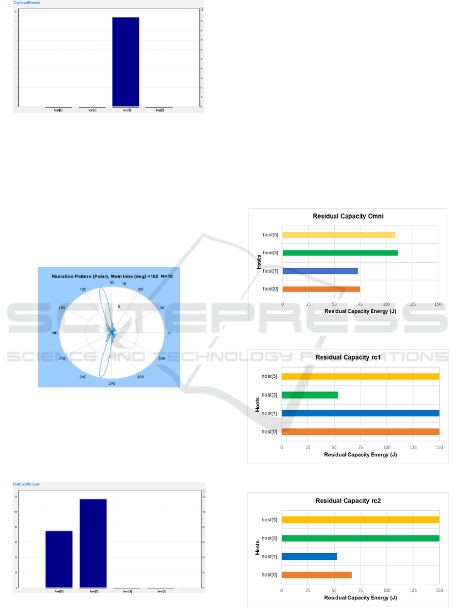
Figure 10: Received Packets Omnet++ statistics (rc1).
As we could expect, data packets flow is directed
toward host 3 because its angular position compared
to sender node (host 7). Other receiver nodes, have a
negligible power reception value, due to their
angular position. Furthermore, side lobes amplitude
is very low in this case, consequently they are not
able to receive packets. Second run configuration
presents a main beam angle of 102°, other
parameters are the same of rc1. It shows radiation
polar pattern in this case:
Figure 11: Array Factor Polar Plot for N=10, φ
0
= 102°, d
= 0.5λ.
Now we have maximum side lobes gain of about
2.5 dB, so side lobe power may be not fully negligi-
ble in this case. Next figure shows received packets
statistic among all receivers:
Figure 12: Received Packets Omnet++ statistics (rc2).
In this case, data packets are mainly directed to
host 1 which is situated within main lobe region, but
due to power contribution of major side lobes, a
fraction of packets will be received by host 0 also
according with our powerAlgorithm. In particular,
from .log analysis we observed that main side lobes
present an amount power of 5 mW that is not negli-
gible with respect to maximum power value in main
lobe region of 10 mW. For a further validation of the
model we also analyzed the results related to the
energy consumption of each receiver node; for this
purpose, we inserted energy simulation modules into
each mobile node setting the initial energy value of
each node to 150 J, and the shutdown energy value
to 0 J. For Analyzing the energy consumption of
nodes, we collected the Residual Capacity statistics
produced by Omnet++:
Figure 13: Residual Capacity Omnidirectional Config..
Figure 14: Residual Capacity rc1 Config..
Figure 15: Residual Capacity rc2 Config..
A New Switched Beam Smart Antenna Model for Extending Inet Omnet++ Framework
269

From Fig. 13 we can observe that the energy
consumption is uniformly distributed between
nodes; in Fig. 14, instead, we can note that the nodes
that are not in the main lobe region preserve its en-
ergy amount. In particular, all energy is conveyed
toward the host that is within the main lobe region.
Furthermore, in Fig. 15 the energy consumption is
preserved, except from host 0 that suffers from the
effect of the sidelobes. Because energy consumption
results clearly reflect values obtained in packet sta-
tistics, we can conclude that our designed module is
functional and could be used for allowing asymmet-
rical and directional communications as extension of
Omnet++ features. Finally, it is shown a summary
Table that compares the main features of the most
used network simulators discussed in sec. 3:
Table 2: Network simulators features comparison.
Network Simulator
Open
Source
Asymmetrical
Comms Sup-
port
SAS Sup-
port
NS-2 yes partial no
NS-3 yes no no
OPNET no partial no
OMNET++
(default Inet)
yes no no
OMNET++
(our Inet)
yes yes yes
Although Opnet and Ns-2 provide some patches
to support asymmetrical communications between
nodes, they do not provide any Smart Antenna Mod-
ule by default; therefore, with respect to Opnet, Om-
net++ is an open source Software that can be en-
hanced by developers. In this regard, our work
demonstrated that, through some appropriate modi-
fications, Omnet++ could be improved in terms of
features, becoming more useful for end users espe-
cially in beamforming and directional antenna con-
texts.
7 CONCLUSIONS
We proposed to extend Inet framework of Omnet++
simulator adapting original source logical structure
also to network systems that supports directional and
asymmetric communications. For this purpose, we
presented a Switched beam smart antenna approach
applied to a real network scenario where mobile
nodes are equipped with directional antennas. After
designing directional antenna module, through sev-
eral modifications accomplished on original mod-
ules, we demonstrated that, applying a very simple
algorithm for managing the power of nodes, de-
pendently on their positions, we can convey data
traffic flows only towards a specific direction; re-
sults showed that, using this approach, instead of the
classical omnidirectional mode, it can be achieved a
considerable energy saving also obtaining a larger
coverage range due to gain value in the main beam
region. Typically, this value is greater than 1 and
depends on geometrical structure of used array. An-
yway, when we drive the main lobe in a certain di-
rection, we have to consider the entity of sidelobes.
Our analysis, also investigated about this situation,
evaluating a case in which sidelobes power value is
not negligible with respect to main lobe power; in
this regard simulation results demonstrated that
some nodes which are not located in main lobe re-
gion could receive sent packets. This effect need to
be accounted in the protocol design at higher layers
such as Mac and Network Layers.
REFERENCES
Chu L.J., 1948 “Physical limitations of omnidirectional
antennas, ”Journ.Appl.Phys., vol. 19, pp. 1163–1175
Khuzhali, S., 2014 “Energy Efficient Topology Based on
Demand for MANETS Using Directional Antenna”
Middle-East Journal of Scientific Research
Dimitrou T., Kalis A., 2004” Efficient Delivery of Infor-
mation in Sensor Networks Using Smart Antennas”,
Chapter “Algorithmic Aspects of Wireless Sensor
Networks Volume” 3121. pp 109-122
Sengar K., Rani N.,Singhal A.,Sharma D., Verma S.,
Singh T., 2014 “Study and CapacityEvaluation of SI-
SO, MISO and MIMO RF Wireless Communication
Systems” IJETT – Vol.9.
Kulkarni S., Bhavani V., 2014 “Study on Smart Antenna
Systems and Implementation in Mobile Ad Hoc Net-
works”, IJERA, Vol. 4.
Balanis C., Ioannides P.,2007” Introduction to Smart An-
tennas”, Lecture #5, Morgan & Claypool.
Wei L.,2004” Smart antennas and MAC protocols in
MANET”,
Christu M.R., Namrata C., John M., Shibin D. , 2013 “A
Comprehensive Overview on Different Network
Simulators”, IJET
Patel P.D., 2007 “Fundamentals of Phased Arrays”, As
tron, Netherland
Orfanidis S.J., ”Electromagnetic Waves and Antennas”
Ch.20: Antenna Arrays , Rutgers ECE
Uribe P., Maureira J.C., Dalle O. 2010 “Extending INET
Framework for Directional and Asymmetrical Wire-
less Communications”. ICST Workshop
Nasipuri A., Li K., Sappidi, U.R. 2002 “Power Consump-
tion and Throughput in Mobile Ad Hoc Networks us-
ing Directional Antennas”, IEEE Int. Conf. on Comm.
And Networking
SIMULTECH 2017 - 7th International Conference on Simulation and Modeling Methodologies, Technologies and Applications
270

Charbonneau N.,2010 “Using Tcl and ns2 01/2010 Tcl and
ns2: Tutorial”
2014, NS-3 Simulator ns-3 Tutorial Release ns-3.15 ns-3
project
Dunaytsev R. 2012:” Network Simulators OPNET Over-
view and Examples”.
2016, Omnet++ Network Simulator User Manual 4.6 Ver-
sion
Inzillo V., De Rango F., 2016 “A Directional Mac Ap-
proach Extending Omnet++ Simulator”, Summer
Computer Simulation Conference 2016 (SCSC), Can-
ada
A New Switched Beam Smart Antenna Model for Extending Inet Omnet++ Framework
271
