
ARTag, AprilTag and CALTag Fiducial Marker Systems: Comparison in
a Presence of Partial Marker Occlusion and Rotation
Artur Sagitov
1
, Ksenia Shabalina
1
, Leysan Sabirova
1
, Hongbing Li
2
and Evgeni Magid
1
1
Intelligent Robotics Department, Higher School of Information Technology and Information Systems,
Kazan Federal University, Kremlyovskaya str. 35, Kazan, Russian Federation
2
Department of Instrument Science and Engineering, Shanghai Jiao Tong University, Shanghai, China
Keywords:
Fiducial Marker, ARTag, AprilTag, CALTag, Occlusion, Experimental Comparison.
Abstract:
Fiducial marker systems consist of patterns that are placed in environment and are automatically detected
with a camera using appropriate for the marker detection algorithm. Marker systems are useful for many
modern visual applications such as augmented reality, robot navigation and collaboration, industrial and space
robotics, and human-robot interaction. A variety of applications demands certain quality assurance for marker
properties. Among the most common criteria are resistance to partial occlusion and rotation, sensitivity to
lightning conditions, marker size, false positive and false negative rates. This paper compares three types of
markers for their resistance to partial occlusion in various types of occlusion and resistance to normal, lateral,
and longitudinal rotations. Intensive experimental comparison of tags is presented with analysis. Detection of
markers was performed with a common Web camera. Based on our experimental results, we have selected a
marker system, which should be preferred for real world applications when only simple inexpensive hardware
is available and appearance of rotation and occlusion disturbances are expected in the environment. Our long
term goal is to calibrate humanoid robot manipulators in real-world environment applying a pre-calibrated
camera of the robot, while the presented in this paper results help selecting a most suitable marker system for
further calibration procedures.
1 INTRODUCTION
Fiducial markers, also referred as tags, are placed
in a physical environment to provide object track-
ing, alignment, and identification. The application
of marker systems ranges from industrial marker sys-
tems, where markers are designed to label parts in
manufacturing and store certain information e.g ship-
ping data, to systems where markers are used for lo-
calization, e.g augmented reality and others. Exam-
ples of the first case are Maxicode marker system,
which is used by the US Postal Service, DataMa-
trix and QR (Quick Response) systems. In turn, for
augmented reality ARToolKit and ARTag marker sys-
tems were integrated into Mars Science Laboratory,
NASA’s Spacecraft 3D smartphone app and other AR
Unity applications. Fiducial markers are also popu-
lar and useful in multiple fields of robotics. Mark-
ers allow to calibrate cameras and mechanical parts of
robotic systems, which are required for industrial ap-
plications (Klimchik et al., 2016), social human-robot
interaction (Pipe et al., 2014) and humanoids (Khu-
sainov et al., 2015), SLAM (Buyval et al., 2017), res-
cue robotics (Magid and Tsubouchi, 2010), robot col-
laboration (Panov and Yakovlev, 2017), swarm con-
trol (Ronzhin et al., 2016) and other fields.
Tag design directly depends on its application. For
example, Maxicode, Qr and DataMatrix are appli-
cable for locating on train cars, that allow machin-
ery to automatically identify and route them through
stations; CyberCode has 2D grid of black and white
squares, and could communicate digital information.
Most markers that are used in augmented reality ap-
plications have at least four feature points that help
determining position and orientation of the markers
and cameras (Hirzer, 2008). Typically, these markers
have square edges and four corner points are used to
calculate a position in three-dimensional space.
This paper we briefly overview various fiducial
marker systems and focus on comparing ARTag,
AprilTag, and CALTag marker systems in presence
of occlusion. The three selected tags are paired with
182
Sagitov, A., Shabalina, K., Sabirova, L., Li, H. and Magid, E.
ARTag, Apr ilTag and CALTag Fiducial Marker Systems: Comparison in a Presence of Partial Marker Occlusion and Rotation.
DOI: 10.5220/0006478901820191
In Proceedings of the 14th International Conference on Informatics in Control, Automation and Robotics (ICINCO 2017) - Volume 2, pages 182-191
ISBN: Not Available
Copyright © 2017 by SCITEPRESS – Science and Technology Publications, Lda. All rights reserved
corresponding error correction methods to recover the
data when some of the bits are incorrectly read (Fiala,
2004). As a comparison benchmark, we use marker
reliability and detection rate in presence of occlusions
of various types and intensity as well as resistance to
normal, lateral, and longitudinal rotations. The ex-
periments were performed with a simple inexpensive
Web camera. Based on our experiments, we con-
cluded that among the three selected marker systems
CALTag system should be preferred for real world
applications when only simple inexpensive hardware
is available and we expect the appearance of rotation
and occlusion disturbances in the environment. As a
global goal, we plan to select the most suitable tag for
camera calibration of the humanoid robot hardware in
real-world environment.
The rest of the paper if organized as follows.
Section 2 describes ARTag, AprilTag, and CALTag
marker systems in details but the details of the under-
lying algorithms and their implementation are out of
scope of this paper due to space limitations. Sections
3 and 4 present experiment design and experimental
results respectively. Finally, we conclude and discuss
future work directions in Section 5.
2 FIDUCIAL MARKERS
Most markers have a common design feature an out-
lining square shape frame with a pattern image in-
side, which encodes information. The square shape
is popular due to four special points (that correspond
to the square corners) detection, which allow cam-
era calibration and marker position calculation. To
reduce light sensitivity, configuration planar marker
systems use monochrome (bitonal) markers (Hirzer,
2008). This way the need to identify shades of grey
is avoided, and a per pixel decision is reduced to a
threshold decision only. In this section, we intro-
duce ARTag, AprilTag and CALTag marker systems.
These markers have two stages of detection: unique
features detection and identification (or recognition)
stage (Fiala, 2005b). First stage searches an image
for a unique feature (quadrilateral shapes). The sec-
ond stage validates an interior of the shape to deter-
mine if the feature is a marker or another object. The
markers have different design, detection and recogni-
tion algorithms, which determine their strengths and
weaknesses in different situations. Typical metrics
for marker systems performance evaluation are: oc-
clusion resistance (marker partial or complete overlap
by other objects), inter-marker confusion (probability
of confusion between markers), resistance to lighting
conditions changes, size of the marker (or distance to
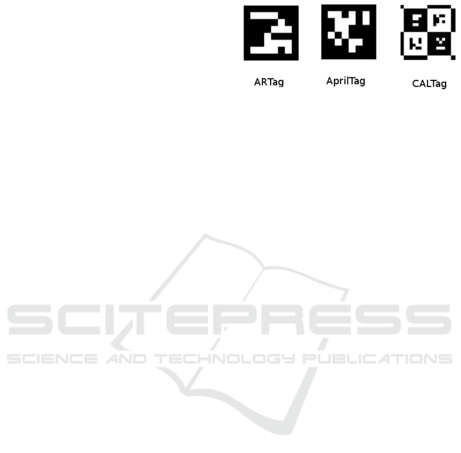
Figure 1: ARTag, AprilTag and CALTag markers example.
the marker) (Fiala, 2005a) etc. Figure 1 demonstrates
examples of ARTag, AprilTag and CALTag.
2.1 ARTag
ARTag (Fig. 1, left) is planar marker system, which
was presented by Mark Fiala in 2004 (Fiala, 2004)
and was inspired by ARToolKit - a library in C and
C++ languages, which was created for Augmented
Reality applications in 1999 by Hirokazu Kato and
Mark Billinghurst (Kato and Billinghurst, 1999). AR-
Toolkit marker is a square shape with a black border
and user-defined image inside. The system has a sim-
ple detection and recognition algorithm: the use of
image binarization for detection and mapping of po-
tential markers with a set of marker patterns. If a
marker is successfully mapped, its internal value is
read. However, this system has a number of draw-
backs that include false positive effect (falsely report-
ing the presence of a marker when none is present)
and inter marker confusion (when a marker is de-
tected, but the wrong ID was given, i.e. one marker
was mistaken for another) (Fiala, 2005a).
The ARTag system uses the same concept of
squares with an internal image inside, but unlike AR-
ToolKit, the system uses a digital approach to read
an internal pattern that is a binary code (barcode).
ARTag system contains 2002 individual tags of square
shape, 1001 markers have a white frame and 1001
markers have a black frame with an image (barcode)
inside. Marker system detects tags with edge points
based approach: edge point detector finds edge pix-
els that form segments, which are then grouped into
quadrilaterals. A marker internal image forms a 6x6
cell grid, which is composed of black and white cells,
each representing 36 bit-values of ”1” and ”0” . First
10 bits of 36 constitute marker ID, remaining 26 bits
are redundant and are used to detect and correct er-
rors and to insure uniqueness of four possible marker
orientations (Fiala, 2005a). ARTag system ensures
fast marker identification as it does not require match-
ing its internal marker image with a library of stored
templates, as it was previously implemented in AR-
ToolKit.
ARTag, AprilTag and CALTag Fiducial Marker Systems: Comparison in a Presence of Partial Marker Occlusion and Rotation
183
2.2 AprilTag
AprilTag marker system (Fig. 1, center) was devel-
oped by April Robotics Laboratory at the University
of Michigan (Olson, 2011). AprilTag is applicable for
a wide range of tasks: camera calibration, robotics,
augmented reality etc. It allows to calculate exact po-
sition, orientation and identity of a marker relatively
to a camera. The detection process consists of sev-
eral stages: searching for linear segments, detecting
squares, calculating the position and orientation of the
tag, decoding the barcode.
The detection process consists of several stages:
searching for linear segments, detecting squares, cal-
culating the position and orientation of the tag, decod-
ing the barcode. Directed linear segments search uses
similar to the ARTag approach, and then sequences of
segments are processed to form a square. Square de-
tection applies a recursive 4-level depth search and at
each level, the tree adds one side of the square. At the
identification stage the validity of the barcode inside
the discovered marker is verified. To encode an inter-
nal picture, AprilTag uses a lexicode system charac-
terized by two parameters: number of codeword (in-
ternal pattern) bits and minimal Hamming distance
between any two codes. Lexicode generates codes
for tags, which allows detecting and fixing bits errors.
AprilTag has several marker families that differ in two
parameters: the number of bits to encode and the min-
imal Hamming distance. For example, ”Tag36h11”
means a 36-bit marker (6x6 array) with a minimal
Hamming distance of 11 bits between any two codes;
”Tag16h5” refers to a 16-bit marker (4x4 array) with
a minimal Hamming value of 5 bits between any two
codes.
AprilTag system is characterized by an increased
number of different codes (barcodes), an increased
number of bit errors that could be detected and cor-
rected, reduced false positives and confusion between
the tags, a reduced total number of bits in the tag, and
a decreased marker size.
2.3 CALTag
After analysis of classical chessboard-based camera
calibration and fiducial markers approach, CALTag
marker was proposed as a specially designed for cam-
era calibration solution (Atcheson et al., 2010). This
system consists of two components: marker design
and detection algorithm. A calibration marker is used
in a proposed calibration grid, which is externally
identical to a chessboard. The tags layout within this
grid has two variations on tags density. A grid with a
highest markers density provides a larger number of
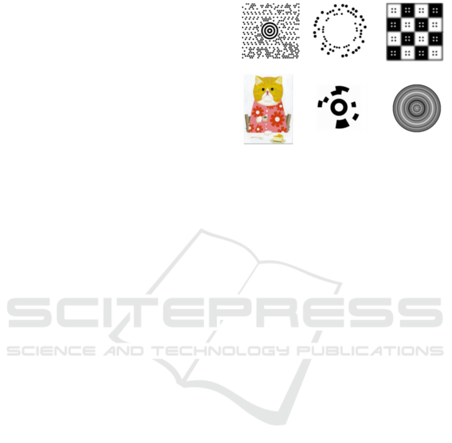
Figure 2: Other fiducial marker systems. MaxiCode , Rune-
Tag and Blur tag (top set of images, from left to right). ART-
Tag, CanTag and Fourier tag (bottom set of images, from
left to right).
calibration points and is thus more reliable and effi-
cient for recognition. Each marker consists of M x N
matrix of black and white squares, which are encapsu-
lated with a border that contains strictly black or white
pixels (Fig. 1, right). After initial detection of poten-
tial markers, they are filtered and verified by access-
ing their binary codes. Any missed calibration points
of the template are restored as the chessboard layout is
known by CALTag system. The binary marker code is
validated by calculating the first P bits checksum and
comparing it with a checksum that is obtained from
four possible marker positions.
2.4 Other Fiducial Marker Systems
Examples
Below we present several other examples from a huge
variety of existing marker systems in order to famil-
iarize a reader with other approaches to marker sys-
tem design and applications. Figure 2 demonstrates
examples of the presented in this subsection markers.
• MaxiCode is a high-capacity, two-dimensional
machine-readable code, that were created for
shipper and load-receiving systems. The code
is reduced to one standard size - one inch per
one inch, with tolerances corresponding to ther-
mal laser printing. The US Postal Service uti-
lizes Maxicode marker in order to handle shipping
information regarding the product: in query any
product information may be included, e.g., prod-
uct weight, serial number, material type, classifi-
cation, degree of danger. Yet, Maxicode is not rec-
ommended for the use as a fiducial marker system
because it does not perform satisfactorily under
the perspective distortion and large field of view
cameras (Fiala, 2005a).
ICINCO 2017 - 14th International Conference on Informatics in Control, Automation and Robotics
184

• RuneTag is a marker system, that was pro-
posed by University of Venice (Bergamasco et al.,
2011). The marker is characterized by a circular
arrangement of dots at fixed angles containing one
or several concentric rings. The marker is built by
partitioning a disk into several evenly distributed
sectors. Each sector, in turn, can be divided into
several concentric rings - levels and the level de-
termines a slot where a dot can be placed. Each
dot has a radius that is proportional to the level
at which the dot is located. With a help of the
generated design, some information could be en-
crypted into a tag, and also allows to easily local-
ize it. RuneTag authors emphasize that it is a high
resistance to occlusion tag, and claim that it was
successfully detected with up to 70% of its area
occlusions in their experiments.
• BlurTag system algorithm relies on the ability to
detect blurred patterns. For this reason, the au-
thors (Reuter et al., 2012) designed a checker-
board pattern that is well suited to estimate point
spread functions (PSFs) and could be robustly de-
tected in a presence of blur. The idea of mak-
ing an out-of-focus pattern with a wide range of
possible focus settings while maintaining a full
coverage of an image and a comparable apparent
resolution of a target at different distances with-
out changing the target pattern. In (Reuter et al.,
2012) the authors presented the dependence of
square detection on the level of blur kernel size
(sigma) and camera resolution, and claimed that
BlurTag demonstrated its strengths with gradually
increasing amount of blur at sufficient image reso-
lution, while CALTag marker system failed to re-
sist equivalent levels of blur.
• ARTTag is an aesthetic fiducial marker system,
which actually can be designed in any colour,
shape and other features with circle pairs, that
allow camera detection, identification and pose
estimation. Fiducial can be placed in everyday
environment and guarantee high level of robust-
ness and accuracy with a help of circle pairs (Hi-
gashino et al., 2016).
• Cantag is an open source software toolkit for
building Marker-based Vision (MBV) systems
that can identify and locate markers (Rice et al.,
2006). System implements two design types of
tags: circle shape (CircleTag) and square border
(SquareTag). Square tags carry a larger symbolic
data payload than a circular marker of the same
size, whereas circular tags offer better location
and pose accuracy.
• Fourier Tag is synthetic fiducial marker used to
Figure 3: ARTag marker system with IDs 2, 3, 6, 34 (from
left to right).
visually encode information and provide control-
lable positioning (Sattar et al., 2007). This marker
could be used for interactive control, e.g., employ-
ing fiducial markers to directly facilitate human-
robot interaction. For example, it could be useful
for a scuba driver to communicate with a swim-
ming robot vehicle to indicate desired actions or
behaviours.
3 EXPERIMENTAL SETUP
Our experimental work compares ARTag, AprilTag
and CALTag marker resistance to occlusion and ro-
tations relatively to various axis. We define occlu-
sion as a partial overlapping of a marker with other
objects. For rotation resistance validation, normal,
lateral, and longitudinal rotations were applied. This
Section presents experiment setup and design.
Each ARTag and AprilTag marker has its own
unique ID, which is encoded in the internal pattern
of the tag. For experiments with ARTag and AprilTag
particular marker IDs were selected randomly.
ARTag ID is encoded in 10 bits of 36 bits and it
determines a unique bit sequence that passes through
several stages to produce a 36-bit binary sequence,
which is encoded in the marker as white and black
cells (Fiala, 2005a). We randomly selected ARTag
markers with IDs 2, 3, 6, and 34 (Fig. 3).
All AprilTags were selected from 36h11 tags fam-
ily, i.e., each of marker ID is encoded in a 36 bit code-
word with a minimum Hamming distance of 11 bits.
Each ID of AprilTag was encoded in a 36 bit code-
word using coding system based on lexicodes (Tracht-
enbert, 1996). Lexicodes are greedily generated error-
correcting codes. Lexicographic code system is char-
acterized by two parameters: number of codeword
(internal pattern) bits n and minimal Hamming dis-
tance between any two codes d. Generation of valid
codewords works as follows: a codeword is added to a
Figure 4: AprilTag marker system with IDs 4, 6, 8, 9 (from
left to right).
ARTag, AprilTag and CALTag Fiducial Marker Systems: Comparison in a Presence of Partial Marker Occlusion and Rotation
185
codebook only when its distance corresponds at least
to the specified distance d to each previous codeword
added to the codebook. The lexicode always starts
with a zero code. For example, to generate a binary
lexicode of length n=3 and minimum Hamming dis-
tance d=2, we would set up Table 1, where indicates
that the vector is a valid codeword. AprilTag system
uses modification of the lexicode algorithm and re-
jects tags with a too simple codewords, which would
produce simple geometric patterns (Olson, 2011). We
utilize arbitrarily selected tags with IDs 4, 6, 8, and 9
(Fig. 4).
Table 1: Lexicode with length n=3 and Hamming distance
d=2.
Vector 000 001 010 011 100 101
Valid c c c
Image capturing during experiments was per-
formed with Genius FaceCam 1000X camera. It
should be noted that a low quality camera for the ex-
periments was selected on purpose in order to ver-
ify the marker capabilities for inexpensive hardware.
Secondly, this selection simplified the experimental
process as the camera was directly connected to a PC
and we avoided a necessity to collect images from
robot cameras and further transfer them to a PC.
For each marker we provided the same condi-
tions of room illumination and camera posture with
respect to the tag. To analyse the effect of occlu-
sion on marker recognition, we selected four differ-
ent ARTag markers (IDs 2, 3, 6, 34), four AprilTag
markers (IDs 4, 6, 8, 9) and two CALTag tags (4x4
and 9x6 grid size). Four types of experiments were
conducted: pure marker rotation around various axis,
systematic occlusion, arbitrary overlap with an ob-
ject, and a combination of systematic occlusion with
marker rotation.
For the experiments, we set up rotation axis with
regard to the observing camera (Fig. 5,). X -axis (lon-
gitudinal axis), which is responsible for roll rota-
tions of a marker, is orthogonal to the marker plane,
passes through a central point of the contact line of
the marker image and its supporting plane, and points
out in the direction of the camera. Y -axis (lateral
axis), which is responsible for pitch rotations of a
marker, coincides with the contact line of the marker
image and its supporting plane. Z-axis (normal axis),
which is responsible for yaw rotations of a marker,
passes through a central point of the contact line of
the marker image and its supporting plane and points
upward from the in the supporting plane, thus com-
pleting a right-hand coordinate frame.
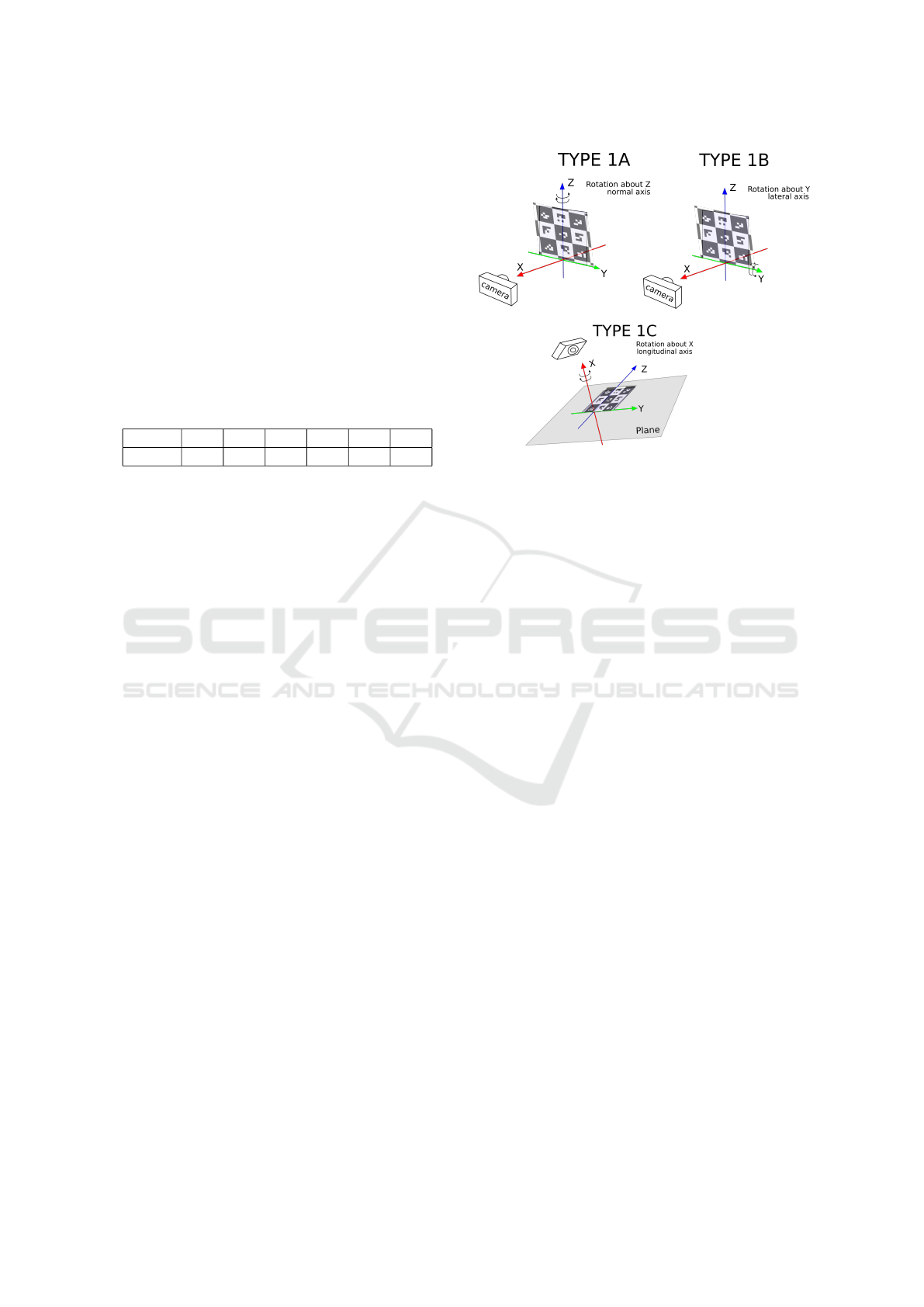
Figure 5: Marker rotation axis.
3.1 Type 1 Experiments: Marker
Rotation
In the first set of experiments (Fig. 5, Type 1A), each
of the markers was fixed at two points that formed
a vertical rotation axis being drawn from a top to a
bottom of a marker and passing through the marker
centre. Then the rotation was performed around this
normal axis, which corresponds to yaw axis. The rota-
tion was performed clockwise and counter-clockwise
for 10, 20, 30 ,45, and 55 degrees in both direc-
tions (Fig. 6 demonstrates an experiment with April-
Tag marker).
In the second set of experiments (Fig. 5,Type 1B),
each marker was fixed with its bottom on a support
plane and the contact line was used as a horizon-
tal rotation axis (lateral axis), which corresponds to
pitch axis. The rotation was performed clockwise and
counter-clockwise for 10, 20, 30, 45, 55 and 65 de-
grees in both directions (Fig. 7 demonstrates an ex-
periment with AprilTag marker).
In the third set of experiments (Fig. 5,Type 1C),
each marker was fixed at its central point and the rota-
tion was performed clockwise and counter-clockwise
around longitudinal axis for 0, 22.5, 45, 67.5, and 90
degrees in both directions.
3.2 Type 2 Experiments: Systematic
Occlusion
In systematic occlusion experiments a part of each
marker was covered with a white paper template of
a rectangular shape, and the template size was gradu-
ally increased. The template was growing from image
bottom to the top so that it would hide 0%, 10%, 20%,
ICINCO 2017 - 14th International Conference on Informatics in Control, Automation and Robotics
186
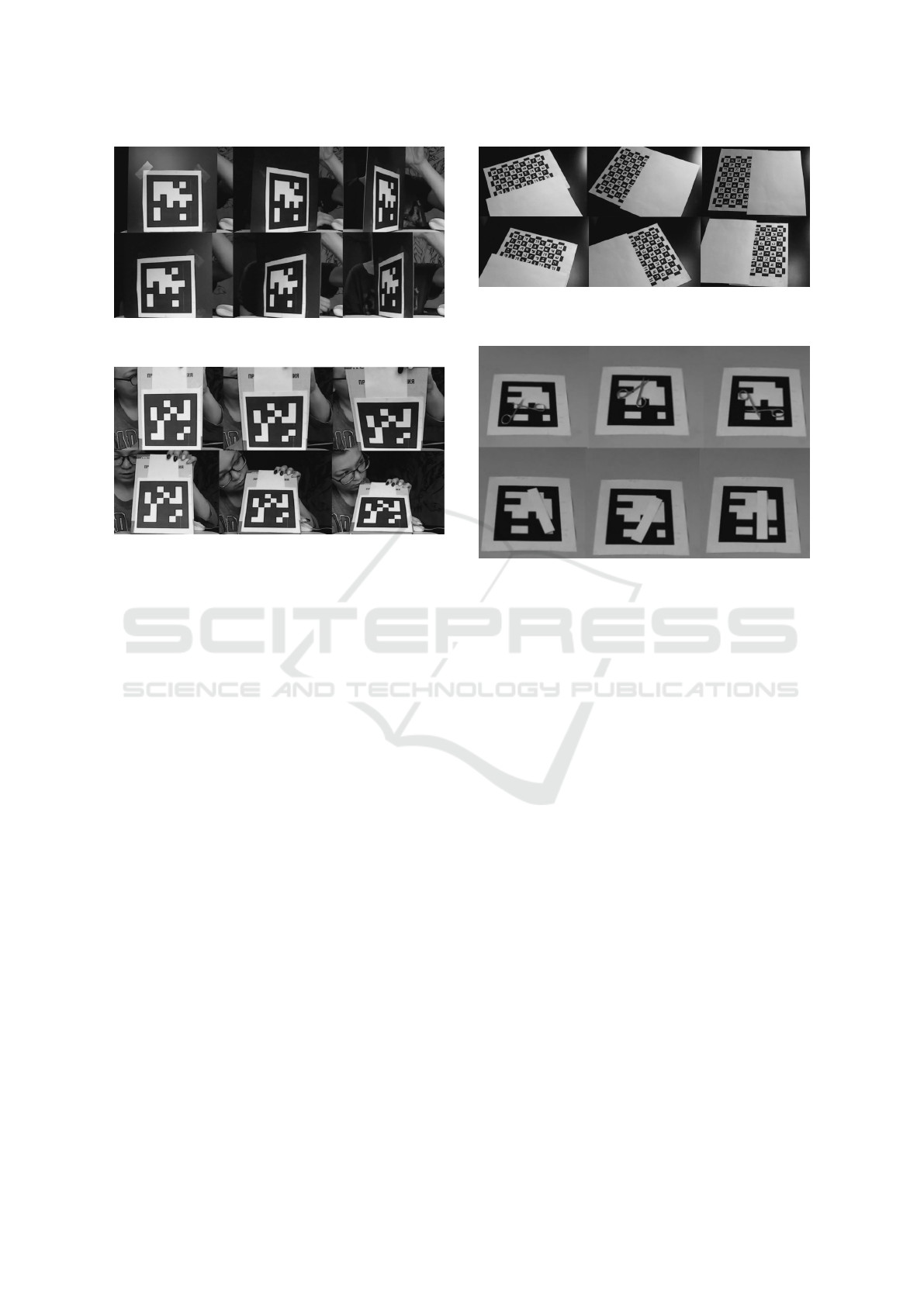
Figure 6: AprilTag ID 4 marker rotation around normal axis
for 10, 45 and 65 degrees.
Figure 7: AprilTag ID 9 marker rotation around lateral axis
for 20, 45, and 65 degrees.
50%, and 70% of the markers area. Figure 8 demon-
strates an example of type 4 experiments for CALTag
marker, but it explains well the idea behind template
growth for type 2 experiments.
3.3 Type 3 Experiments: Marker
Rotation with Systematic Occlusion
In marker rotation with systematic occlusion experi-
ments the first (Type 1C) and the Type 2 of experi-
ments were combined together. The marker was ro-
tated clockwise and counter-clockwise around longi-
tudinal axis in its plane for 0, 22.5, 45, 67.5, and 90
degrees and simultaneously occluded with the white
paper template for 0%, 10%, 20%, 50%, and 70% of
its area. Figure 8 demonstrates an example of the ex-
periments for CALTag marker. Rotations relatively to
normal and lateral axes with a simultaneous system-
atic occlusion are left for the future work.
3.4 Type 4 Experiments: Arbitrary
Overlap with an Object
In arbitrary overlap with an object experiments each
marker was randomly overlapped with one of three
different objects so that an object was entirely located
within tags area and thus the overlap percentage was
always kept constant. The first object was a white
thick paper strip of 13 cm width and 2.5 cm length
Figure 8: CALTag marker rotation around longitudinal axis
for 22.5, 67.5 and 90 degrees in both directions with an oc-
clusion of 20% of its area.
Figure 9: Arbitrary overlap of the ARTag ID3 with the scis-
sors (top set of images) and the white strip object (bottom
set of images).
with 32.5 cm
2
area. The second object was a metal
scissors with 7.99 cm
2
area. The third object was a
black plastic strip of 15,7 cm width and 2.6 cm length
with 40.82 cm
2
area. This way, for each experiment
the constant overlap percentage was always known
in advance. In the case of the black strip, it covers
the interior and also crosses the boundaries of each of
marker (Fig. 10). In the case of the white strip and
the scissors, they cover only the internal pattern of
each marker (Fig. 9). With each of three object for
each marker 25 trials were conducted. We emphasize
a special case for the 4x4 size CALTag: if the black
and the strip white strip is placed strictly along the
marker side, the occupied area percentage decreases
as the width of the strips exceed marker size. In this
case, the overlap percentage varies between 25.5%
and 33.84% in for the white strip and between 26.53%
and 40.20% for the black strip.
4 EXPERIMENTAL RESULTS
For the experiments we used the available for public
use official software of AprilTag and CALTag. For
ARTag we used ArUco library, which allows detect-
ing and recognizing various kinds of marker fami-
lies (Garrido-Jurado et al., 2014). The markers were
ARTag, AprilTag and CALTag Fiducial Marker Systems: Comparison in a Presence of Partial Marker Occlusion and Rotation
187
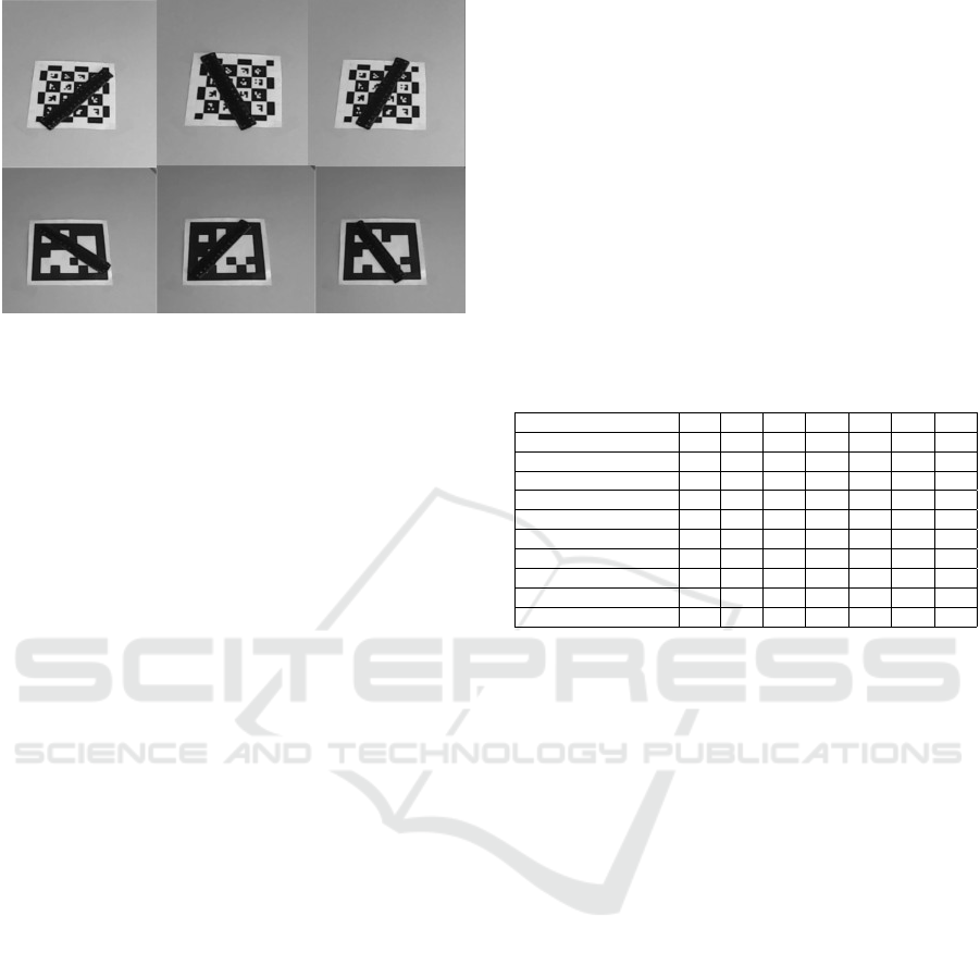
Figure 10: Arbitrary overlap of the CALTag 4x4 (top set of
images) and AprilTag (bottom set of images) with the black
strip object.
printed on white paper with the following sizes:
• ARTag: 15.2 x 15.2 cm, total area 231.04 cm
2
• AprilTag: 13.5 x 13.5 cm, total area 182.25 cm
2
• CALTag 4x4: 9.8 x 9.8 cm, total area 96.04 cm
2
• CALTag 9x6: 21.7 x 14.7 cm, total area 318.99
cm
2
It is important to notice that the two types of oc-
clusion, systematic and arbitrary, had slightly differ-
ent experimental implementation. For systematic oc-
clusion, which is reflecting a very typical real world
occlusion situation, a marker becomes partially visi-
ble due to its rotation and incline in 3D space. Arbi-
trary occlusion had the overlapping object completely
within internal pattern of the marker, which effected
only the recognition stage of marker pattern detection.
The experimental results for ARTag (ID 2, ID 3,
ID 6, ID 34), AprilTag (ID 4, ID 6, ID 8, ID 9) and
CALTag (4x4 and 9x6 sizes) are summarized in Ta-
bles 2-12. Tables 2-9 present the results of systematic
occlusion experiments. ”2/2” denotes a successful de-
tection of the marker in both (clockwise and counter-
clockwise) directions for normal axis (Table 2) and
lateral axis (Table 3) rotations. ”1/2” denotes suc-
cessful detection of the marker only in one of the di-
rections, while ”0/2” denotes a failure to detect the
marker in both directions of rotation.
AprilTag and CALTag markers demonstrated
strong resistance to normal and lateral rotations: they
were successfully detected and recognized at any
tested angle (0, 10, 20, 30, 45, 55, and 65 degrees) for
both rotation directions. ARTag markers were sen-
sitive to any normal axis rotations. For lateral axis
rotations the ARTag markers failures started at 10 de-
grees rotation, but showed more resistance for lateral
rotations comparing with normal axis rotations. In
particular, ARTag markers were sensitive to large ro-
tation angles of 55 and 65 degrees. In the case of
lateral rotation for these angles, two markers (ARTag
with ID=3 and ARTag with ID=6) were not detected
in one of the directions.
Tables 4-7 demonstrate the results of marker ro-
tation around longitudinal axis with a simultaneous
systematic occlusion; percentage of marker occlusion
appears in the first column of the tables, while rotation
degree appears in the first row. Table 8 summarizes
the results of successful detection rate with regard to
the marker occlusion percentage for all markers. Ta-
ble 9 summarizes the results of successful detection
rate with regard to the marker rotation degree around
longitudinal axis for all markers.
Table 2: Systematic approach: rotation around normal axis.
Tag / Rotation percent 0
◦
10
◦
20
◦
30
◦
45
◦
55
◦
65
◦
ARTag (ID 2) 2/2 2/2 2/2 2/2 2/2 1/2 0/2
ARTag (ID 3) 2/2 2/2 2/2 2/2 2/2 2/2 0/2
ARTag (ID 6) 2/2 2/2 1/2 2/2 2/2 0/2 0/2
ARTag (ID 34) 2/2 2/2 2/2 1/2 2/2 1/2 0/2
AprilTag (ID 4) 2/2 2/2 2/2 2/2 2/2 2/2 2/2
AprilTag (ID 6) 2/2 2/2 2/2 2/2 2/2 2/2 2/2
AprilTag (ID 8) 2/2 2/2 2/2 2/2 2/2 2/2 2/2
AprilTag (ID 9) 2/2 2/2 2/2 2/2 2/2 2/2 2/2
CALTag 4x4 2/2 2/2 2/2 2/2 2/2 2/2 2/2
CALTag 9x6 2/2 2/2 2/2 2/2 2/2 2/2 2/2
Table 10 demonstrates the results of arbitrary
overlap with an object experiments for the black strip
object. As the markers have different sizes while
the strip size is constant, the percentage of occluded
marker area differs between the markers.
The strip was arbitrarily placed within an inter-
nal part of the marker. For each marker, twenty five
experiments were performed so that the position of
the strip on the marker was different in each exper-
iment. The black colour of the strip makes it diffi-
cult to read binary code of the marker since all mark-
ers are bitonal (monochrome) and the strip crosses
the marker boundaries. A special case was CAL-
Tag 4x4 marker: because of its small size, the over-
lapped (by the strip) area varied from 25.5 to 33.84
percent. ARTag and AprilTag demonstrated particular
sensitivity to marker edges overlapping when marker
boundaries were overlapped with a black strip. Edge
overlapping disables marker unique feature (edge) de-
tection, which in turn results into a failure of marker
discovery (recognition) stage. At the same time,
CALTag 4x4 and 9x6 were successfully detected al-
most in all experiments (46 out of 50 experiments),
which demonstrates CALTag resistance to overlap-
ping boundaries and a part of it’s internal pattern area.
Table 11 shows the results of arbitrary overlap
with an object experiments for the scissors object.
These experiments demonstrated the dependence of
ICINCO 2017 - 14th International Conference on Informatics in Control, Automation and Robotics
188
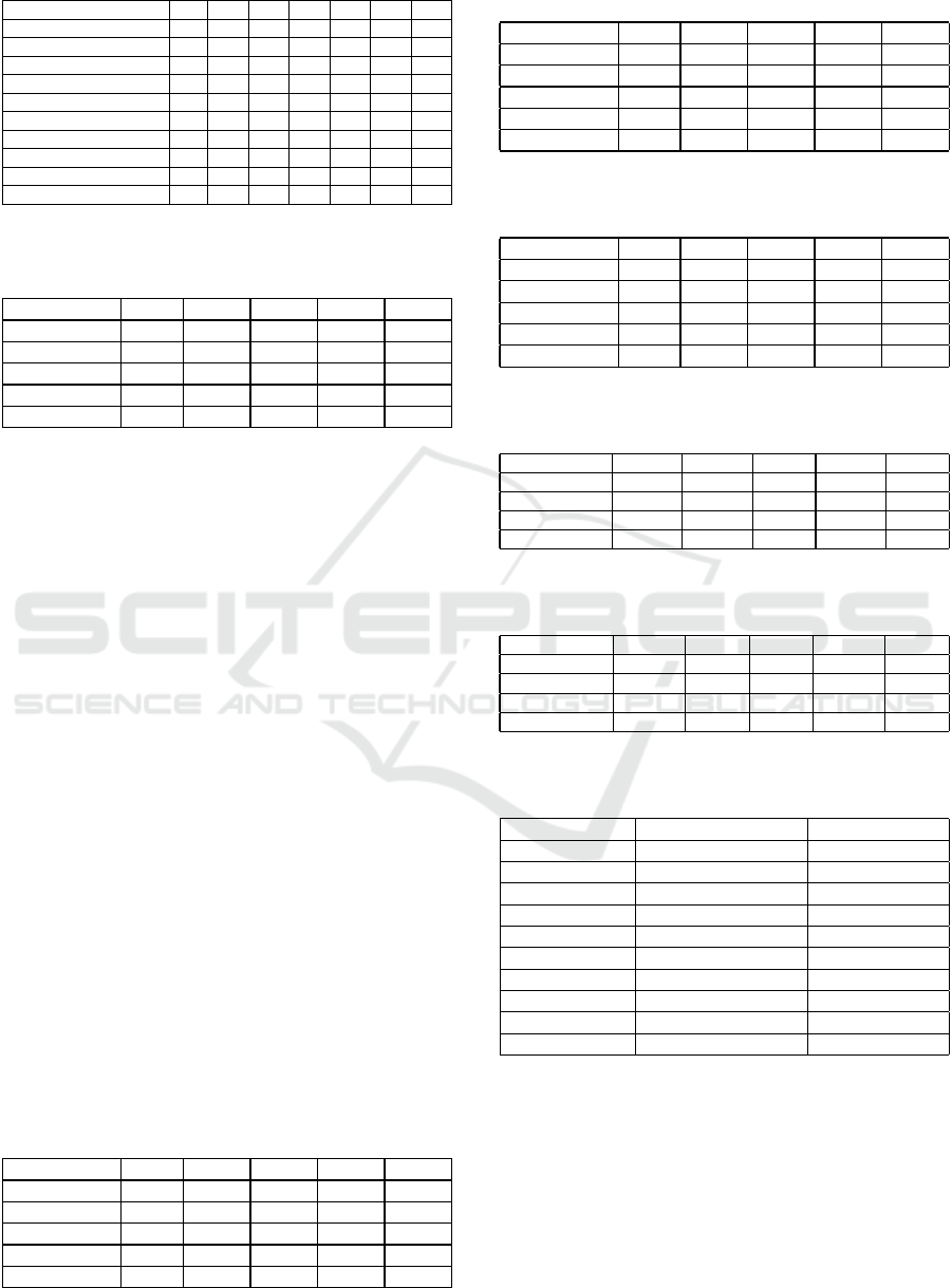
Table 3: Systematic approach: rotation around lateral axis.
Tag/ Inclination percent 0
◦
10
◦
20
◦
30
◦
45
◦
55
◦
65
◦
ARTag (ID 2) 2/2 2/2 2/2 2/2 2/2 2/2 2/2
ARTag (ID 3) 2/2 2/2 1/2 1/2 1/2 1/2 1/2
ARTag (ID 6) 2/2 2/2 2/2 2/2 1/2 1/2 1/2
ARTag (ID 34) 2/2 1/2 2/2 2/2 2/2 2/2 2/2
AprilTag (ID 4) 2/2 2/2 2/2 2/2 2/2 2/2 2/2
AprilTag (ID 6) 2/2 2/2 2/2 2/2 2/2 2/2 2/2
AprilTag (ID 8) 2/2 2/2 2/2 2/2 2/2 2/2 2/2
AprilTag (ID 9) 2/2 2/2 2/2 2/2 2/2 2/2 2/2
CALTag 4x4 2/2 2/2 2/2 2/2 2/2 2/2 2/2
CALTag 9x6 2/2 2/2 2/2 2/2 2/2 2/2 2/2
Table 4: Systematic approach: occlusion and rotation
around longitudinal axis of AprilTag.
Occl. / Rot. 0
◦
22
◦
45
◦
67
◦
90
◦
0% 2/2 0/2 0/2 0/2 0/2
10% 2/2 0/2 0/2 0/2 0/2
20% 2/2 0/2 0/2 0/2 0/2
50% 2/2 0/2 0/2 0/2 0/2
70% 2/2 0/2 0/2 0/2 0/2
marker recognition algorithm on overlap only the in-
terior of marker with a complex object. CALTag 9x6
and 4x4 showed the best results and high resistance to
any overlap of the interior within an object of a com-
plex shape (scissors). ARTag demonstrated high relia-
bility to occlusion of interior within a complex object
as well. At the sane time, in the case of AprilTag, the
marker system exposed sensitivity to overlapping of
the interior with a complex object: of the one hundred
experiments 15 markers were not recognized, but the
overall results were still satisfactory.
Table 12 shows the result of arbitrary overlap
with an object experiments for the white strip ob-
ject. These experiments demonstrated the dependence
of marker recognition algorithm on overlap of the
marker interior. ARTag system showed the lowest re-
sult relative to other marker systems: of the one hun-
dred experiments only two were successful. This re-
sult confirms that white colour of the strip makes it
difficult to read binary code of the marker as all mark-
ers contain monochrome colours. In case of AprilTag
only 7 experiments were successful out of 100. CAL-
Tag 4x4 markers successful rate was 88% and 9x6
markers successful rate was 96%. CALTag marker
system demonstrated the best resistance to overlap-
Table 5: Systematic approach: occlusion and rotation
around longitudinal axis of ARTag.
Occl. / Rot. 0
◦
22
◦
45
◦
67
◦
90
◦
0% 2/2 0/2 0/2 0/2 0/2
10% 2/2 0/2 0/2 0/2 0/2
20% 2/2 0/2 0/2 0/2 0/2
50% 2/2 0/2 0/2 0/2 0/2
70% 2/2 0/2 0/2 0/2 0/2
Table 6: Systematic approach: occlusion and rotation
around longitudinal axis of CALTag 9x6.
Occl. / Rot. 0
◦
22
◦
45
◦
67
◦
90
◦
0% 2/2 2/2 2/2 2/2 2/2
10% 2/2 1/2 2/2 2/2 2/2
20% 2/2 0/2 1/2 2/2 2/2
50% 2/2 1/2 2/2 2/2 2/2
70% 0/2 1/2 1/2 1/2 2/2
Table 7: Systematic approach: occlusion and rotation
around longitudinal axis of CALTag 4x4.
Occl. / Rot. 0
◦
22
◦
45
◦
67
◦
90
◦
0% 2/2 2/2 2/2 2/2 2/2
10% 2/2 2/2 2/2 2/2 2/2
20% 2/2 1/2 2/2 2/2 2/2
50% 2/2 1/2 2/2 2/2 2/2
70% 2/2 0/2 1/2 2/2 1/2
Table 8: Successful detection rate with regard to the marker
occlusion percentage.
0% 10% 20% 50% 70%
ARTag 100% 0% 0% 0% 0%
AprilTag 100% 0% 0% 0% 0%
CALTag 4x4 100% 100% 90% 90% 50%
CALTag 9x6 100% 90% 70% 100% 30%
Table 9: Successful detection rate with regard to the marker
rotation degree around longitudinal axis.
0
◦
22
◦
45
◦
67
◦
90
◦
ARTag 100% 0% 0% 0% 0%
AprilTag 100% 0% 0% 0% 0%
CALTag 4x4 100% 60% 90% 100% 80%
CALTag 9x6 100% 50% 80% 90% 90%
Table 10: Results of arbitrary overlap experiments with a
black strip object.
Tag Occlusion percent % Recognition rate
ARTag (ID 2) 17.66 0%
ARTag (ID 3) 17.66 0%
ARTag (ID 6) 17.66 0%
ARTag (ID 34) 17.66 0%
AprilTag (ID 4) 22.39 0%
AprilTag (ID 6) 22.39 0%
AprilTag (ID 8) 22.39 0%
AprilTag (ID 9) 22.39 0%
CALTag 4x4 26.53 –40.20 92%
CALTag 9x6 12.79 92%
ping of interior due to markers design and recogni-
tion algorithm (Atcheson et al., 2010). Yet, these re-
sults supported the claim that white colour of the strip
makes it difficult to read binary code of the marker as
all markers contain monochrome colours.
ARTag, AprilTag and CALTag Fiducial Marker Systems: Comparison in a Presence of Partial Marker Occlusion and Rotation
189
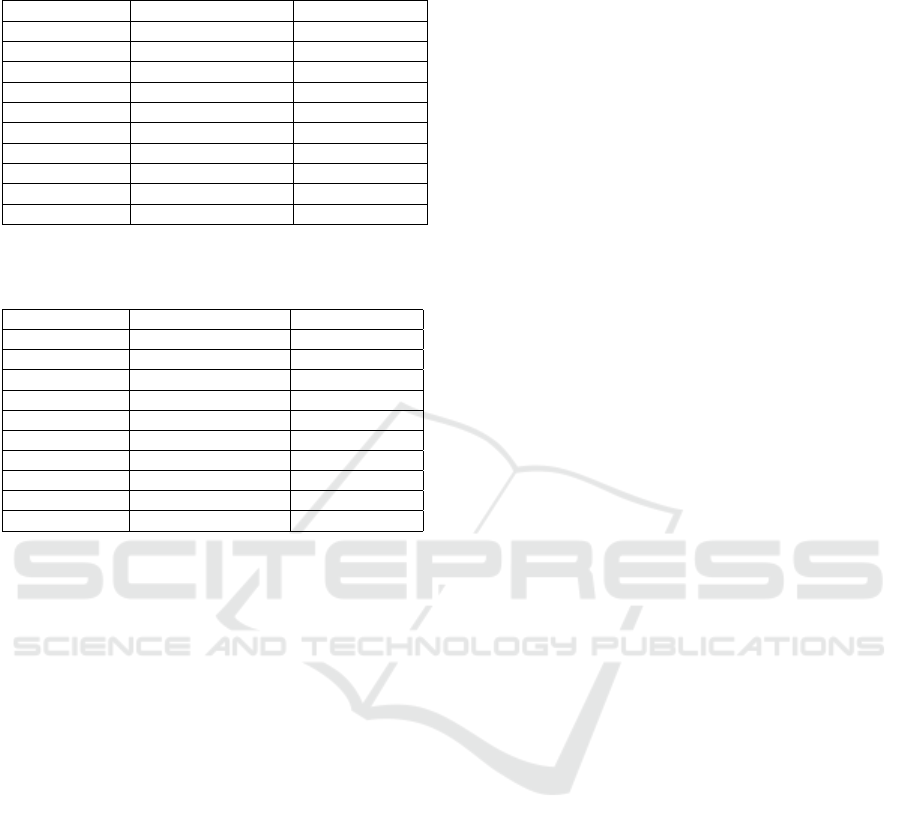
Table 11: Results of arbitrary overlap experiments with a
scissors object.
Tag Occlusion percent % Recognition rate
ARTag (ID 2) 3.45 100%
ARTag (ID 3) 3.45 92%
ARTag (ID 6) 3.45 100%
ARTag (ID 34) 3.45 96%
AprilTag (ID 4) 4.38 76%
AprilTag (ID 6) 4.38 92%
AprilTag (ID 8) 4.38 92%
AprilTag (ID 9) 4.38 80%
CALTag 4x4 8.32 100%
CALTag 9x6 2.5 100%
Table 12: Results of arbitrary overlap experiments with a
white strip object.
Tag Occlusion percent % Recognition rate
ARTag (ID 2) 14.06 4%
ARTag (ID 3) 14.06 4%
ARTag (ID 6) 14.06 0%
ARTag (ID 34) 14.06 0%
AprilTag (ID 4) 17.83 4%
AprilTag (ID 6) 17.83 4%
AprilTag (ID 8) 17.83 20%
AprilTag (ID 9) 17.83 0%
CALTag 4x4 25.5 –32.5 88%
CALTag 9x6 10.18 96%
5 CONCLUSIONS AND FUTURE
WORK
In this paper we described three marker system in de-
tails: ARTag, AprilTag and CALTag. We conducted
experiments with this marker systems to evaluate their
sensitivity for partial occlusion in various types of oc-
clusion and resistance to normal, lateral, and longi-
tudinal rotations. For the given marker types we ran-
domly selected particular markers: four ARTag mark-
ers with IDs 2, 3, 6, 34; four AprilTag markers with
IDs 4, 6, 8, and 9; and two CALTag markers of 4x4
and 9x6 grid size. Occlusion experiments were de-
signed to validate resistance to a systematic occlusion
of a marker and an arbitrary overlap with an object.
For systematic occlusion experiments, which reflects
a very typical real world occlusion situation, a marker
was occluded with a rectangular shaped white colour
template that covered from 0 to 70 percent of total
marker area in a such manner that both marker in-
terior and edges were occluded. For arbitrary over-
lap experiments an object that covers up to 40 percent
of marker area was arbitrarily placed within marker’s
area. Three object were utilized: black strip, white
strip and scissors. The first object crossed the bound-
aries of markers and overlapped interior; the second
and the third objects overlapped only markers interior,
which affected only the recognition stage of marker
pattern detection. Rotation experiments considered
normal, lateral, and longitudinal rotations of a marker
for 0, 10, 20, 30, 45, 55, and 65 degrees. Com-
bined experiments of simultaneous marker rotation
with systematic occlusion were performed only for
rotation around longitudinal axis.
ARTag and AprilTag markers demonstrated high
sensitivity to edge occlusions, which limits their ef-
fective use only to the cases where it could be guar-
anteed that no edge occlusions occur. These mark-
ers performed at satisfactory level for the cases when
the object occluded only the internal part of the mark-
ers. ARTag showed high resistance to overlapping its
interior, while AprilTag demonstrated a greater level
of sensitivity in the same situation. AprilTag demon-
strated high reliability under rotation around normal
and lateral axes in all one hundred experiments. At
the same time, ARTag demonstrated a high vulnera-
bility to rotations, especially with regard to the normal
axis. CALTag showed high resistance to all types of
occlusion. This marker is more resistant to overlap-
ping of interior due to markers design and recogni-
tion algorithm. CALTag was also resistant to rotations
within the complete range of the selected angles. The
lowest recognition rate was within white strip object
experiments, where CALTag 4x4 showed 88% recog-
nition rate (3 experiments out of 25 had failed).
Based on our experiments, we conclude that
among the three selected marker systems CALTag
have demonstrated significantly better results than
ARTag and AprilTag markers. Thus, among the three
systems, CALTag marker system should be preferred
for real world applications when only simple inexpen-
sive hardware is available and we expect the appear-
ance of rotation and occlusion disturbances in the en-
vironment.
As a part of our future work, we plan to conduct
occlusion resistance experiments using different qual-
ity cameras and to identify the strengths and weak-
nesses of the markers using an increased set of cri-
teria, which includes inter-marker confusion, resis-
tance to lighting conditions changes and influence of
marker size (or distance to a marker). Special atten-
tion will be paid to the behaviour of CALTag marker,
which have demonstrated the best performance in our
current empirical research. Our long term goal is to
calibrate cameras and manipulators of a humanoid
robot and of a crawler mobile robot in real-world en-
vironments. The presented in this paper results help
selecting a most suitable marker system for further
calibration procedures. Our on-going experimental
work concentrates on verification of the markers with
ICINCO 2017 - 14th International Conference on Informatics in Control, Automation and Robotics
190

AR-601M robot hardware (Khusainov et al., 2015) in
both laboratory and real-world environments. In ad-
dition to ARTag, AprilTag and CALTag markers, we
are interested to verify the performance of BlurTag
marker system. The later stages of experimental work
will include verification of the markers with Servosila
Engineer robot hardware (Sokolov et al., 2016).
ACKNOWLEDGEMENTS
This work was partially supported by the Russian
Foundation for Basic Research (RFBR) and Min-
istry of Science Technology and Space State of Israel
(project IDs 15-57-06010 and 17-48-160879). Part
of the work was performed according to the Rus-
sian Government Program of Competitive Growth of
Kazan Federal University.
REFERENCES
Atcheson, B., Heide, F., and Heidrich, W. (2010). Cal-
tag: High precision fiducial markers for camera cal-
ibration. In VMV, volume 10, pages 41–48.
Bergamasco, F., Albarelli, A., Rodola, E., and Torsello, A.
(2011). Rune-tag: A high accuracy fiducial marker
with strong occlusion resilience. In IEEE Conf. on
Computer Vision and Pattern Recognition, pages 113–
120.
Buyval, A., Afanasyev, I., and Magid, E. (2017). Compar-
ative analysis of ros-based monocular slam methods
for indoor navigation. In Proc. SPIE 10341, 9th Int.
Conf. on Machine Vision, pages 1–6.
Fiala, M. (2004). Artag revision 1, a fiducial marker system
using digital techniques. National Research Council
Publication, 47419:1–47.
Fiala, M. (2005a). Artag, a fiducial marker system using
digital techniques. In IEEE Conf. on Computer Vision
and Pattern Recognition, 2005, volume 2, pages 590–
596.
Fiala, M. (2005b). Comparing artag and artoolkit plus fidu-
cial marker systems. In IEEE Int. Workshop on Hap-
tic Audio Visual Environments and their Applications,
pages 6–pp.
Garrido-Jurado, S., Mu
˜
noz-Salinas, R., Madrid-Cuevas,
F. J., and Mar
´
ın-Jim
´
enez, M. J. (2014). Auto-
matic generation and detection of highly reliable fidu-
cial markers under occlusion. Pattern Recognition,
47(6):2280–2292.
Higashino, S., Nishi, S., and Sakamoto, R. (2016). Art-
tag: aesthetic fiducial markers based on circle pairs.
In ACM SIGGRAPH, page 38. ACM.
Hirzer, M. (2008). Marker detection for augmented real-
ity applications. In Seminar/Project Image Analysis
Graz, pages 1–2.
Kato, H. and Billinghurst, M. (1999). Marker tracking and
hmd calibration for a video-based augmented reality
conferencing system. In Proc. 2nd IEEE and ACM Int.
Workshop on Augmented Reality, pages 85–94. IEEE.
Khusainov, R., Shimchik, I., Afanasyev, I., and Magid, E.
(2015). Toward a human-like locomotion: modelling
dynamically stable locomotion of an anthropomorphic
robot in simulink environment. In 12th Int. Conf. on
Informatics in Control, Automation and Robotics, vol-
ume 2, pages 141–148.
Klimchik, A., Magid, E., and Pashkevich, A. (2016).
Design of experiments for elastostatic calibration
of heavy industrial robots with kinematic parallelo-
gram and gravity compensator. IFAC-PapersOnLine,
49(12):967–972.
Magid, E. and Tsubouchi, T. (2010). Static balance for res-
cue robot navigation: Discretizing rotational motion
within random step environment. In Int. Conf. on Sim-
ulation, Modeling, and Programming for Autonomous
Robots, pages 423–435. Springer.
Olson, E. (2011). Apriltag: A robust and flexible visual
fiducial system. In IEEE Int. Conf. on Robotics and
Automation, pages 3400–3407.
Panov, A. I. and Yakovlev, K. (2017). Behavior and path
planning for the coalition of cognitive robots in smart
relocation tasks. In Robot Intelligence Technology
and Applications 4: Results from the 4th Int. Conf.
on Robot Intelligence Technology and Applications,
pages 3–20. Springer International Publishing.
Pipe, A., Dailami, F., and Melhuish, C. (2014). Crucial
challenges and groundbreaking opportunities for ad-
vanced HRI. In IEEE/SICE Int. Symposium on System
Integration, pages 12–15.
Reuter, A., Seidel, H.-P., and Ihrke, I. (2012). Blurtags:
spatially varying psf estimation with out-of-focus pat-
terns. In 20th Int. Conf. on Computer Graphics, Visu-
alization and Computer Vision, pages 239–247.
Rice, A. C., Beresford, A. R., and Harle, R. K. (2006). Can-
tag: an open source software toolkit for designing and
deploying marker-based vision systems. In 4th IEEE
Int. Conf. on Pervasive Computing and Communica-
tions, pages 10–pp.
Ronzhin, A., Vatamaniuk, I., and Pavluk, N. (2016). Auto-
matic control of robotic swarm during convex shape
generation. In IEEE Int. Conf. on Electrical and
Power Engineering, pages 675–680.
Sattar, J., Bourque, E., Giguere, P., and Dudek, G. (2007).
Fourier tags: Smoothly degradable fiducial markers
for use in human-robot interaction. In 4th Canadian
Conf. on Computer and Robot Vision, pages 165–174.
Sokolov, M., Lavrenov, R., Gabdullin, A., Afanasyev, I.,
and Magid, E. (2016). 3d modelling and simulation of
a crawler robot in ros/gazebo. In Proc. 4th Int. Conf.
on Control, Mechatronics and Automation, pages 61–
65. ACM.
Trachtenbert, A. (1996). Computational methods in cod-
ing theory. Master’s thesis, University of Illinois at
Urbana-Champaign.
ARTag, AprilTag and CALTag Fiducial Marker Systems: Comparison in a Presence of Partial Marker Occlusion and Rotation
191
