
Automated Driving System based on Roadway and Traffic
Conditions Monitoring
Pavel Beresnev, Anton Tumasov, Dmitry Tyugin, Denis Zeziulin,
Valery Filatov and Dmitry Porubov
Nizhny Novgorod State Technical University n.a. R.E. Alekseev, Minina street, 24, Nizhniy Novgorod, Russian Federation
Keywords: Automated Driving System, Advanced Driver-Assistance Systems, Lane Detection, Traffic Sings Detection,
Obstacle Detection, Light Commercial Vehicles (LCV).
Abstract: In article development of a concept of advanced driver-assistance systems is considered. It consists of
several subsystems such as a warning about leaving the line, warning the driver about the possibility of
collision with an obstacle in the lane, detection of traffic signs. The concept of the system receives visual
information about the road scene and decides on the need for to correct the course and speed parameters of
the traffic. The component structure of system is shown. A number of methods are proposed (Hough
Transform, bird's eye view, etc.) to solve the task. Tests of a concept of advanced driver-assistance systems
are carried out. Based on the results of the tests, a technical task will be formulated for conducting
development work.
1 INTRODUCTION
For many years, studies on advanced driver-
assistance systems (ADAS) have been carried out to
reduce the number of accidents and improve safety
on the roads. The main algorithm of the advanced
driver-assistance systems while driving is the
collection of data from the sensors installed around
the vehicle, further analysis of the information,
detection of a critical situation on the road and
conducting measures to avoid or mitigate the
consequences
Currently the following ADAS are widely
distributed: the lane departure warning system,
obstacle detection system, traffic signs detection,
parking assistant, pedestrian detection system, night
vision system, adaptive cruise control, blind zone
monitoring system etc.
The developed systems are widely used by
automobile manufacturers. According to the
statistics from Bosch GmbH (The journal modern
electronics), the most common advanced driver-
assistance systems are: the lane departure warning
system (LDWS) and the advanced emergency
braking system (AEBS). Moreover, unintentional
departure from the occupied lane causes about 30%
of all accidents on the road.
The development of ADAS is carried out by
many large foreign automobile manufacturers.
However, there are no own developments and
solutions in the Russian Federation, which can be
installed on vehicles in series. To implement the
functions of ADAS on commercial vehicles adapted
to the operational conditions in Russian Federation,
the team of our university together with the GAZ
Group is working on the concept of the advanced
driver-assistance system on the GAZelle Next
vehicle with the possibility to correct the vehicle's
movement via the steering system.
At this stage the concept of the system consists
of:
– Lane departure warning subsystem, defined
by existing road markings;
– Driver warning subsystem, preventing the
possibility of collision with an obstacle on the
lane;
– Subsystem of traffic signs detection.
The concept of system should receive a stream
of data from the front sensors (optical and/or
infrared camera and thermal imager) for further
processing.
The concept of the system receives visual
information about the road scene and decides to
adjust the parameters of the direction and the speed.
Beresnev, P., Tumasov, A., Tyugin, D., Zeziulin, D., Filatov, V. and Porubov, D.
Automated Driving System based on Roadway and Traffic Conditions Monitoring.
DOI: 10.5220/0006700303630370
In Proceedings of the 4th International Conference on Vehicle Technology and Intelligent Transport Systems (VEHITS 2018), pages 363-370
ISBN: 978-989-758-293-6
Copyright
c
2019 by SCITEPRESS – Science and Technology Publications, Lda. All rights reserved
363

2 ANALYSIS OF ADAS
At the first stage of the development, an overview of
information sources concerning the development of
advanced driver-assistance systems has been
performed.
In (Hoang, T., et al., 2016) a method for
detecting road lanes was proposed, which
distinguishes the dotted and solid lines of the road.
Based on the experimental results with the Caltech
open database, this method showed excellent results
over traditional methods for detection road lanes.
The paper (Shanti B., and Ganorkar S., 2015.)
shows the developing of an algorithm for a lane
departure warning system. The system can be used
successfully to reduce the number of road accidents
that have occurred due to the sleepiness or
inexperience of the driver. This paper shows the
research and comparison of the available algorithms.
Authors developed an algorithm for the image
processing, which uses one camera installed on the
vehicle. The stability of the algorithm has been
tested in different conditions, such as lightning,
shadows from adjoining building, vehicles etc. The
algorithm is implemented in two stages. At the first
stage, the algorithm finds the point of descent on the
road, and then carefully selects the segments. The
lines of the roadway were made by using
information about the point of the road boundary. A
heuristic filter was used to check and detect the road
lanes. The Kalman's filter is used in order to track
the road lane and processing the critical sections
where the detection algorithm does not work.
The paper (Janda F., et al., 2013) is presenting a
reliable real-time approach for determining the
edges of roads by obtaining information from the
radar and video camera. The road edge is defined as
the transition from asphalt to off-road. The
integration of the multi-lane detection system is
shown, that makes this approach independent of the
number of lanes and the visibility of the lane marks.
System's performance is evaluated by using the
reference data. Information about road geometry,
curvature and the relative position of the vehicle is
critical for advanced driver-assistance systems
(ADAS). The detection of the road edge is the main
component for proposed functions, such as
preventing the crossing road edge, which keeps the
vehicle on the under control area. This work is the
part of the European project «interactiveIVe» that
explores the new technologies and approaches to
improving vehicle's safety via an integrated
platform.
Paper (Pydipogu P., et al., 2013) describes the
application of the IPM (Inverse Perspective
Mapping) method. The system receives a video
image by the camera installed on the vehicle, and
then uses several processes to detect objects and
road markings. A universal methodology was used
to detect lanes and objects. A simple heuristic
method was developed and it gives reliable results of
detecting and tracking objects and lanes on a video
stream. The heuristic method also gives effective
results in the detection and tracking of several
vehicles, regardless of distance.
An obstacle detection method based on moving
cameras was developed in (Shah V., et al., 2016).
This method was used to detect various obstacles
(animals, traffic signs, obstacles, roadway
irregularities), knowing the size of the roads. A new
technique for detecting obstacles through moving
cameras was proposed, that has several limitations in
comparison with stationary cameras. The latest
research trends were analyzed in this paper.
In the paper (Sumi K., and Arun Kumar M.,
2017.) various methods of detection and recognition
of traffic signs are explained. To detect the traffic
signs and recognize their text, different methods are
applied in order to get the desired accuracy. A
comparative research of the methods is carried out
and their effectiveness is explained. The authors of
the paper suggest dividing the problem of detecting
traffic signs into two stages. The first step is to find
out the area of the desired traffic sign. The second
stage is character recognition.
The system in (Fifik M., et al., 2010) is based on
a two-stage traffic signs detection scheme. Input is
the image that contains the information for
extraction. A block called "Hypothesis Generation"
(HG) generates promising hypotheses in the form of
a Region of Interest (ROI). After this, the part called
Hypothesis Verification (HV) checks or rejects the
previously stated hypothesis. As the output, we have
an image with ROI, which is recognized or
determined during subsequent processing. This
system can be divided into two subsystems. One
subsystem is "fast", consisting of a CSR block and a
classification block; the second is a "slow"
subsystem consisting of image segmentation blocks,
an invariant allocation function, functional memory,
function modification, and type classification blocks.
Also, experiments with this system were carried out.
The average recognition speed of the system was
86% for the Hue, Saturation, Value (HSV) color
area and 89% for the red, green, blue (RGB) color
area. The best results achieved were 3-4 seconds for
image processing.
VEHITS 2018 - 4th International Conference on Vehicle Technology and Intelligent Transport Systems
364

Benchmarking of existing solutions in the area of
advanced driver-assistance systems and autopilot
motion was performed. As the comparative criteria a
list of functions were defined:
1) Means of obtaining information;
2) Detection of the road marking;
3) Detection partially erased road marking;
4) Detection of the road edge;
5) System «follow me»;
6) Detection of vehicles moving towards;
7) Lane assist;
8) Night Vision System;
9) Movement in bad weather and road
conditions (rain, snow, etc.);
10) Algorithms and method of functioning;
The objects of benchmarking were the world
leaders of the development in the area of ADAS and
unmanned ground vehicles. These are General
Motors, Google, nVidia, Tesla, Volkswagen,
Mercedes Benz, Baidu and others.
Regarding the first point of benchmarking almost
all the manufacturers use cameras, it is also possible
to use LIDARs and radars.
Vehicles of all companies are able to detect the
road marking. But only General motors, Tesla and
Volkswagen can detect partly erased road marking.
Only General Motors, Google, nVidia, Baidu can
detect the edge of the road.
To the fifth point of benchmarking list
correspond the vehicles by Google, nVidia, Tesla,
Volkswagen and Baidu. Also these vehicles are able
to detect other vehicles moving towards.
The lane assist is realized practically at all
companies, the big development of this system is
realized at large automobile manufacturers, such as
Volkswagen, Tesla and Mercedes Benz.
Advanced driver-assistance systems in all
presented above vehicles are functioning at night.
But in such bad road conditions as snow, rain, fog,
best work performance is confirmed only by Google,
nVidia, Tesla and Volkswagen.
By having considered information sources and
carrying out benchmarking of existing solutions in
the area of development of advanced driver-
assistance systems, it was revealed that:
– At present, interest in developing or
improving approaches to identifying
obstacles, road lanes and signs is increasing
(as evidenced by the large quantity of
different articles in foreign sources).
– The use of cameras as a means of solving
tasks is topical along with the growth of
appropriate technologies.
– The use of cameras is the cheapest method of
solving the problem of detection objects,
lanes and road signs.
– Based on the conducted benchmarking, it can
be concluded that the integration of advanced
driver-assistance systems into vehicles of the
largest automotive manufacturers has
increased and large-scale research in this area
of leading companies (Google, nVidia, Tesla,
Volkswagen, Mercedes Benz, etc.) are
carried out.
3 DEVELOPMENT OF ADAS FOR
LCV
3.1 Composition of ADAS
Based on the review of actual literature and
benchmarking of advanced driver-assistance
systems, the components of the concept of the lane
detection system, the traffic signs detection and the
obstacles detection on the road was determined.
As optoelectronic sensors, the Basler ace
acA1300-200uc cameras are used. The location of
the cameras is in the sides and in the middle of the
windscreen. The video stream from the cameras is
processed using the nVidia Jetson TX2 platform that
has considerable computing power and small size
that significantly affects the compactness of the
entire system. Based on the analysis of driver
assistance systems, video cameras are not sufficient
for reliable and efficient operation of the entire
recognition system. It is necessary to duplicate
systems of recognition of the road scene by sensors
that can function in difficult operating conditions,
such as erased road lane, poor illumination of roads,
presence of animals on the roadway, etc. In order to
solve the above problems, it is proposed to use
thermal imaging sensors in the system concept. The
TITAN IP thermal imager is used in our system. A
wide range of temperature exploitation allows it to
function in snow, rain, fog and to recognize not only
dynamic objects of the road scene (cars, pedestrians,
animals), but also to determine the boundaries of the
roadway and road markings. The structural scheme
of interaction of the concept of the advanced driver-
assistance systems is presented in Figure 1.
Automated Driving System based on Roadway and Traffic Conditions Monitoring
365
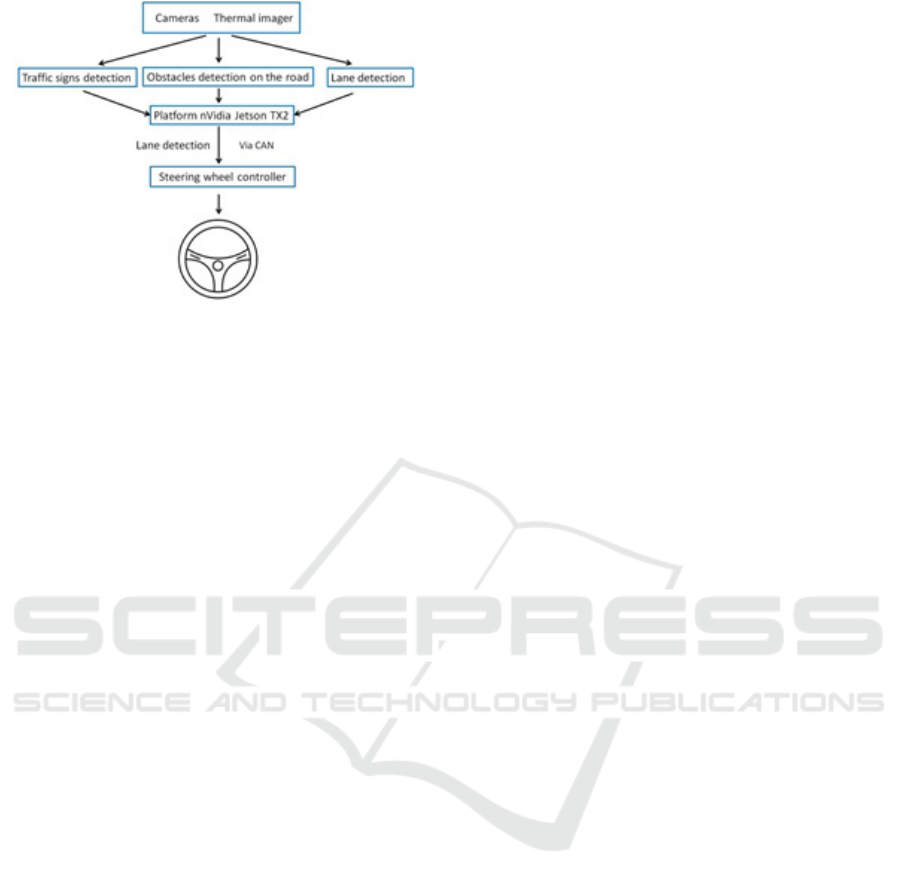
Figure 1: Structural scheme of the interaction of the
driver-assistance systems.
3.2 Detection Method
There are many different approaches and methods
for recognizing road lanes and road signs: B-spline
model (Li W., et al., 2014, Deng J., et al., 2013);
Hyperbola-pair lane model (Tan H., et al., 2014);
Lane geometrical model (Zhou S., et al., 2010);
Vehicle directional control model (DIRCON)
(Litkouhi B., et al., 1993); Quadratic function
model (Yoo H., et al., 2013); IPM model (Shin J., et
al., 2014, Lu W., et al., 2014); Linear or parabolic
model (Mu C., and Ma X., 2014.) etc.
Based on the results of the analysis of possible
recognition methods, as well as taking into account
the efficiency of computing power, two methods of
recognizing road lanes and signs were chosen, this is
the Haar Feature and the Hough Transform (Máthé
K., and Buşoniu L., 2015). The use of these methods
for solving the problem is compared.
Let us single out a number of criteria and
compare the proposed methods.
Basis of the Method:
1. Haar Feature. The Viola-Jones method,
wavelet, Haar primitives;
2. Hough Transform. In the simplest case, the
Hough transform is a linear transformation to detect
straight lines or boundaries.
Training:
1. Haar Feature. A database of images of the
object sought in real-world conditions and a
database of images without the desired object are
needed. The cascade learns by examples, creating a
set of rules for finding this object in xml format;
2. Hough Transform. No.
Identification Method
1. Haar Feature. In the entire matrix of the
frame, it searches for a region suitable for a
particular xml rule;
2. Hough Transform. The Hough's Transform
algorithm uses an array called the accumulator to
determine the presence of a direct (special case) y =
mx + b. The dimension of the accumulator is equal
to the number of unknown parameters of the
Hough's area. Search is carried out by means of
mathematical transformations.
Restrictions
1. Haar Feature. It is necessary to collect raw
data directly at the target location of the detector.
Any change in incoming data (changes in
illumination, weather conditions, color
characteristics, camera angle) adversely affects the
result of detection. The algorithm is sensitive to the
rotation angle of the sought object;
2. Hough Transform. The efficiency of the
algorithm follows from the quality of the input data:
the boundaries of the figures during the
preprocessing of the image must be clearly defined.
The use of Hough's transform on noisy images is
difficult. For noisy images, a preprocessing step is
required to suppress noise.
Advantage
1. Haar Feature. High speed of work, the ability
to detect complex objects;
2. Hough Transform. High speed of work. It is
possibility the detection of simple geometric shapes.
Based on the analysis, the Hough Transform was
chosen as the main algorithm for detecting traffic
signs and lanes.
3.2.1 Obstacles Detection on the Road
The TenforFlow Object Detection API is used, that
allows creating and training object detection models
based on neural networks to determine objects on
the route,
The TensorFlow Object Detection API is an
open source platform based on the TensorFlow
library that allows you to create and training object
detection models. The model is a set of files that
contain information necessary for the recognition of
certain objects. The finished model is the result of
training of the neural network. Before training, a
description file for detection objects is created, as
well as set of data for each object on which the
neural network will conduct it’s training. The
training and debugging of neural network requires
large computing power.
In the first stage (Figure 2), the obstacle
detection system was tested on a video stream from
a dash camera with a minimum number of obstacles
(vehicles).
VEHITS 2018 - 4th International Conference on Vehicle Technology and Intelligent Transport Systems
366
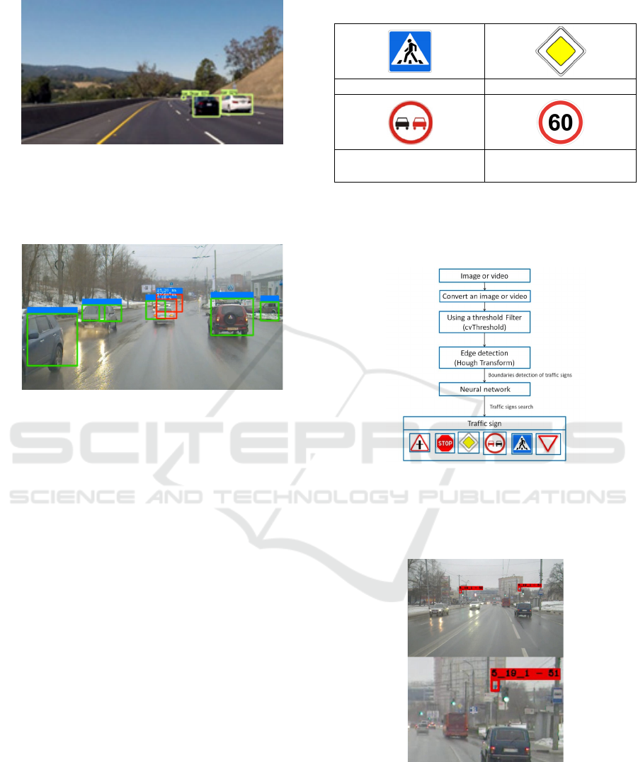
Figure 2: The first tests of the system on video files.
At the end of the first stage, the system was
modernized and tested on a real road conditions.
Figure 3 shows the frames tests of the system.
Figure 3: Example of system tests on a video stream of
road conditions in the city of Nizhny Novgorod.
Upon completion of the system testing, a
conclusion was made about the operability of this
method.
3.2.2 Traffic Sign Detection
The system of automatic recognition of traffic signs
is an important part of ADAS. It is designed to
notify the driver of the presence of traffic signs on
the road. The system can help the driver follow the
speed limit established on the road section, observe
travel restrictions, overtaking, etc.
Based on the chosen Hough Transform, the
model of recognizing road signs on the roadway was
developed. The development of the model was
carried out with the open source library OpenCV
(OpenCV: library) of computer vision algorithms,
image processing and numerical algorithms for
general purpose.
In order to design the algorithm, a number of
traffic signs were used in accordance with the
national standard of the Russian Federation
№52290-2004 (National standard of the Russian
federation). The list of traffic signs is presented in
Table 1.
Table 1: List of used road signs.
Crosswalk The main road
No overtaiking Speed limit
This algorithm allows finding the necessary sign,
only if it is available in the database.
For the operation of this algorithm, an image
conversion circuit has been designed.
Figure 4: The image conversion scheme.
Based on this conversion scheme, a number of
tests were carried out. Screen shots of the results are
shown in Figure 5.
Figure 5: Screenshot of the system's output.
With regard to the recognition of road signs, the
system showed an efficiency that meets the
requirements, which is 96%, but it is necessary to
expand the list of recognizable road signs for the
most complete analysis of the road scene.
Automated Driving System based on Roadway and Traffic Conditions Monitoring
367
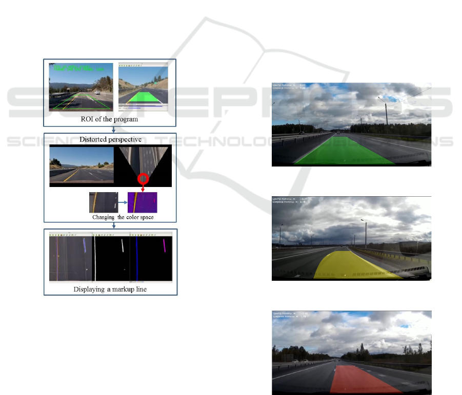
3.2.3 Lane Detection
The software of the road line detection system is
based on the bird's eye view algorithm. Using this
algorithm, with respect to solving the current task,
allows you to display the selected section of the
roadway in a distorted perspective. The scheme of
this algorithm is shown in Figure 6.
As a region of interest (ROI), the trapezoidal
image area is selected. This approach allows
excluding unnecessary artifacts (untreated frame
substrate) after a perspective distortion in the case of
using a rectangular shape as the ROI.
By selecting the optimal parameters, an
acceptable perspective view of the road section can
be obtained. Then, there is a transformation of the
image of ROI to the distorted perspective image.
To further process the resulting mapping, the
matrix must be transferred from the RGB color
space to the HSV color space. This space is less
sensitive to light and shade changes in the frame,
which allows increasing the stability of the
algorithm on complex sections of the road.
Figure 6: The scheme of the bird's eye view algorithm.
After the transition to the desired color space, the
important preprocessing of image is binarization.
The purpose of binarization is to exclude from
the frame all insignificant pixels that are not related
to road markings (all pixels outside the color range
of white and yellow markings).
To search for lines in the frame, the above-
mentioned Hough transform is used.
When the function receives the binarized image
of the prospective road as the input, it returns the
vector of lines that can be used to identify the lines
found in the frame.
After receiving a vector of lines, it is necessary
to approximate all set in order to get one line
corresponding to the position of the road line in the
frame.
After carrying out virtual tests and optimizing
the system for detecting road marking, an algorithm
was further developed for warning about lane
departure and tests were conducted in real road
conditions.
The algorithm of the lane departure warning
system is as follows. There are 3 warning zones:
green - the car is in the center of the lane; yellow -
deviation from the center of the lane is in the range
from 0.2 to 0.3 m; red - deviation from the center of
the lane is more than 0.3 meters (Figure 7-9).
During the tests, the car speed was about 70 ± 10
km/h, entering the turn by a radius of curvature of at
least 100 m and keeping the speed at a given level.
After that the car performed a successive smooth
approach to the road marking at a speed of 0.3 m/s.
About 100 tests have been performed.
Figure 7: Example of the warning algorithm. Green zone.
Figure 8: Example of the warning algorithm. Yellow zone.
Figure 9: Example of the warning algorithm. Red zone.
VEHITS 2018 - 4th International Conference on Vehicle Technology and Intelligent Transport Systems
368
The triggering did not happen, if in the process
of making the vehicle closer to less than 30
centimeters with the line marking, no alert was
given.
Based on the results of the tests, the following
data were evaluated: the number of correct alarms
when approaching the marking lines; the number of
false alarms when approaching; number of failures
when approaching.
The calculated accuracy of the recognition of
marking lines was 0.76. The completeness, which
shows the number of correct responses from the total
number of real intersections of the road marking
line, was 0.92. The indicator of the quality of the
system was 84%.
3.3 Steering System
The developed concept of the system is planned to
be installed on the GAZ Group's light commercial
vehicles (GAZ Group).
GAZelle NEXT vehicles are equipped with a
rack-and-pinion with a hydraulic booster steering
system, which causes difficulties for the integration
of advanced driver-assistance systems due to the
cumbersomeness of the whole system and the
complex technique of controlling the pump of the
hydraulic system. Thus it was suggested to use a
steering rack with an electric motor with the control
capability. This steering rack shows similar strengths
on the steering wheel that allows it to be used for
GAZ Group commercial vehicles.
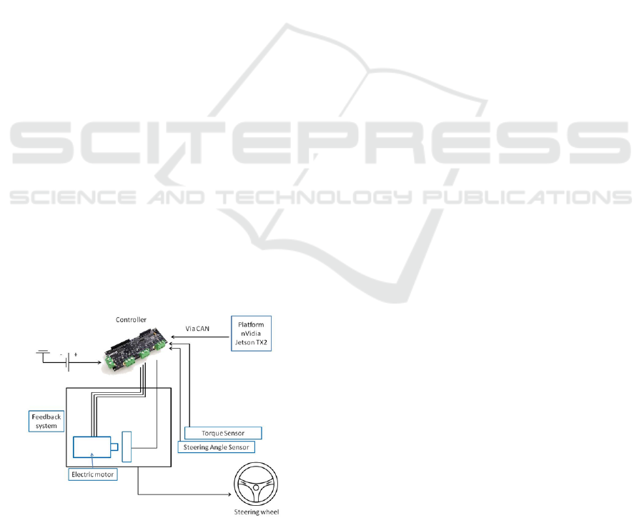
Based on the received and processed data from
the lane detection system, the nVidia Jetson TX2
platform sends a signal to the steering controller
with the electric motor via the CAN bus of the
vehicle.
Figure 10: Steering system.
The controller controls the electric motor of the
steering rack, sending the necessary signals via the
data bus. This method is the most secure and allows
minimizing the possibility of losing control of the
steering rack. The scheme of the system is shown in
Figure 10.
Knowing the necessary distance to the side lane,
the width of the lane and the width of the vehicle,
the system is able to correct the movement of the
vehicle, keeping it on the lane and does not allow to
leave the lane.
4 CONCLUSIONS AND FUTURE
WORK
Information sources were reviewed and
benchmarking of existing solutions in the field of
driver assistance systems, including autopilot
technologies have been made.
Based on the analysis, the component
composition of the concept system and the
interaction scheme have been proposed.
Methods for solving the problem are proposed.
The efficiency of the proposed methods was
confirmed by a number of tests.
Combining systems for detecting road markings,
signs, and obstacles along the way provides the
opportunity to obtain the necessary information
about the road scene in order to implement correct
control actions on the steering mechanism.
The scheme of course orientation control by
means of electromechanical system is developed.
Timely impact of the electric motor through the
servo-drive to the steering rack allows keeping the
car in the lane, thereby increasing safety and
reducing the probability of unintentional crossing of
the lane.
At this stage of the project the structure of
system of the ADAS-3 (SAE J3016) level is
developed.
The problems in the technical implementation of
the active steering system for light commercial
vehicles of the GAZ Group have been solved.
The system works in various weather conditions
and the heavy climate of the Russian Federation.
The next stage of the project is the development
of design documentation for various vehicle
systems, software and data transmission networks
that integrate all subsystems into a single network in
the on-board computer.
The prototype of the system concept will be
installed on the GAZelle Next vehicle and examined
at the GAZ Group’s test site for debugging all of the
components. Based on the results of the tests,
Automated Driving System based on Roadway and Traffic Conditions Monitoring
369

recommendations will be given in order to to
compile the Technical Assignment for development
work.
ACKNOWLEDGEMENTS
This research done with the financial support from
Ministry of Education and Science of the Russian
Federation in the frame of the complex project “The
establishment of the high-tech manufacturing of safe
and export-oriented GAZ vehicles with autonomous
control systems and the possibility of integration
with the electric platform on the base of components
of Russian production” under the contract
№03.G25.31.0270 from 29.05.2017 (Governmental
Regulation №218 from 09.04.2010).
REFERENCES
Deng J., Kim J., Sin H., Han Y., 2013. Fast lane detection
based on the B-spline fitting. Int. J. Res. Eng. Tech., 2,
134–137.
Fifik M., Turán J., Ovseník L., Fazekas K., 2010.
Experiments with a Transform based Traffic Sign
Recognition System, Proc. of 17th International
Conference on Systems Signals and Image Processing
IWSSI P2010, pp. 227-230, June 17–19.
GAZ Group. Retrieved October 30, 2017, from:
http://gazgroup.ru/
Hoang, T., Hong, H., Vokhidov, H., Park, K., 2016. Road
Lane Detection by Discriminating Dashed and Solid
Road Lanes Using a Visible Light Camera Sensor.
Sensors 2016, 16, 1313.
Janda F., Pangerl S., Schindler A., 2013. A Road Edge
Detection Approach for Marked and Unmarked Lanes
Based on Video and Radar, 16th International
Conference on Information Fusion, July 9-12.
Litkouhi B., Lee A., Craig D., 1993. Estimator and
Controller Design for Lanetrak, a Vision-Based
Automatic Vehicle Steering System. In Proceedings of
the 32nd Conference on Decision and Control, San
Antonio, TX, USA, 15–17; pp. 1868–1873.
Li W., Gong X., Wang Y., Liu P., 2014. A Lane Marking
Detection and Tracking Algorithm Based on Sub-
Regions. In Proceedings of the International
Conference on Informative and Cybernetics for
Computational Social Systems, Qingdao, China, 9–10;
pp. 68–73.
Lu W., Rodriguez F., Seignez E., Reynaud R., 2014.
Monocular Multi-Kernel Based Lane Marking
Detection. In Proceedings of the 4th Annual
International Conference on Cyber Technology in
Automation, Control, and Intelligent Systems, Hong
Kong, China, 4–7; pp. 123–128.
Máthé K.; Buşoniu L., 2015. Vision and Control for
UAVs: A Survey of General Methods and of
Inexpensive Platforms for Infrastructure Inspection.
Sensors 2015, 15, 14887-14916.
Mu C., Ma X., 2014. Lane detection based on object
segmentation and piecewise fitting. TELKOMNIKA
Indones. J. Electr. Eng., 12, 3491–3500.
NATIONAL STANDARD OF THE RUSSIAN
FEDERATION №52290-2004 Traffic control devices.
Traffic signs. General technical requirements.
On-road Automated Vehicle Standards Committee, 2014.
SAE J3016: Taxonomy and Definitions for Terms
Related to On-Road Motor Vehicle Automated
Driving Systems. SAE International.
OpenCV library. Retrieved October 30, 2017, from:
https://opencv.org/
Pydipogu P., Fahim M., Shafique M., 2013 Robust lane
detection and object tracking In relation to the
intelligence transport system. Master’s Thesis
Electrical Engineering Signal Processing.
Shah V., Maru S., Jhaveri R., 2016. An Obstacle Detection
Scheme for Vehicles in an Intelligent Transportation
System, Int. J. Comput. Netw. Inf. Secur., vol. 8, no.
10, pp. 23–28.
Shanti B., Ganorkar S., 2015. Real-Time Lane Detection
for Driving System Using Image Processing.
International Research Journal of Engineering and
Technology (IRJET), Volume: 02 Issue.
Shin J., Lee E., Kwon K., Lee S., 2014. Lane Detection
Algorithm Based on Top-View Image Using Random
Sample Consensus Algorithm and Curve Road Model.
In Proceedings of the 6th International Conference on
Ubiquitous and Future Networks, Shanghai, China, 8–
11; pp. 1–2.
Sumi K., Arun Kumar M., 2017. Detection and
Recognition of Road Traffic Signs - A Survey.
International Journal of Computer Applications (0975
- 8887), Volume 160 - No.3.
Tan H., Zhou Y., Zhu Y., Yao D., Li K., 2014. A Novel
Curve Lane Detection Based on Improved River Flow
and RANSA. In Proceedings of the International
Conference on Intelligent Transportation Systems,
Qingdao, China, 8–11; pp. 133–138.
The journal modern electronics. Retrieved October 30,
2017, from: https://www.soel.ru/rubrikator/rynok/
Yoo H., Yang U., Sohn K., 2013. Gradient-enhancing
conversion for illumination-robust lane detection.
IEEE Trans. Intell. Transp. Syst., 14, 1083–1094.
Zhou S., Jiang Y., Xi J., Gong J., Xiong G., Chen H.,
2010. A Novel Lane Detection Based on Geometrical
Model and Gabor Filter. In Proceedings of the IEEE
Intelligent Vehicles Symposium, San Diego, CA,
USA, 21–24; pp. 59–64.
VEHITS 2018 - 4th International Conference on Vehicle Technology and Intelligent Transport Systems
370
