
Dynamical Investigation of Crawling Motion System based on a
Multistable Tensegrity Structure
Philipp Schorr
1
, Valter B
¨
ohm
2
, Lena Zentner
3
and Klaus Zimmermann
1
1
Technical Mechanics Group, Department of Mechanical Engineering, Technical University of Ilmenau,
Max-Planck-Ring 12, 98693 Ilmenau, Germany
2
Technical Mechanics, Department of Mechanical Engineering, Ostbayerische Technische Hochschule Regensburg,
Galgenbergstr. 30, 93053 Regensburg, Germany
3
Compliant Systems Group, Department of Mechanical Engineering, Technical University of Ilmenau,
Max-Planck-Ring 12, 98693 Ilmenau, Germany
Keywords:
Worm-like Motion, Multistable Tensegrity Structure.
Abstract:
The basic idea of this article is the utilization of the multistable character of a compliant tensegrity struc-
ture to control the direction of motion of a crawling motion system. A crawling motion system basing on a
two-dimensional tensegrity structure with multiple stable equilibrium states is considered. This system is in
contact with a horizontal plane due to gravity. For a selected harmonic actuation of the system small oscillati-
ons around the given equilibrium state of the tensegrity structure occur and the corresponding uniaxial motion
of the system is evaluated. A change of the equilibrium state of the tensegrity structure yields to novel con-
figuration of the entire system. Moreover, the motion behavior of the novel configuration is totally different
although the actuation strategy is not varied. In particular, the direction of motion changes. Therefore, this
approach enables a uniaxial bidirectional crawling motion with a controllable direction of motion using only
one actuator with a selected excitation frequency.
1 INTRODUCTION
The increasing significance of mobile robotics in en-
gineering applications requires a continuous impro-
vement of the current systems respective to the ope-
rating sensors and actuators. Moreover, as conse-
quence of the advanced demands on those systems
even the investigation of novel motion principles is
necessary. For example, applications like the mini-
mal invasive surgery allow only an extremely limited
working space which prevent the use of conventional
motion systems basing on wheels or legs. Therefore,
innovative motion principles basing on the direct in-
teraction to the environment are required.
A promising approach is the investigation of cra-
wling motion systems. This principle is copied from
the motion behavior of earth worms observed in the
nature. The peristaltic motion bases on the alternating
shortening and lengthening of several body segments.
Moreover, the presence of spike which are added at
the body of the earth worm are essential for the mo-
tion. Hence, a forward or backward motion occurs
depending on the orientation of these spikes.
Beside the biological aspects of the worm-like
motion groups of researchers are also interested in
this motion principle from the mechanical point of
view. In (Steigenberger and Behn, 2012), (Zimmer-
mann et al., 2009a) and (Zimmermann et al., 2013)
the earth worm is modeled by a finite number of rigid
body which are connected by kinematic drives. The
mechanical behavior of the mentioned spikes is mo-
deled by anisotropic friction properties and the occur-
ring motion behavior is investigated. But as conse-
quence of the anisotropy of the friction properties a
preferred direction of motion occurs and the use of
the opposite direction of motion is not possible for
a harmonic actuation. In (Bolotnik et al., 2006) and
(Zimmermann et al., 2009b) the actuation of an addi-
tional internal mass is investigated in order to control
the direction of motion for isotropic friction proper-
ties. Moreover, in (Fang and Xu, 2011) and (Fang
and Xu, 2012) the actuation by the kinematic drive is
varied to maximize the steady state velocity. Howe-
ver, for isotropic friction properties advanced requi-
rements are demanded on the actuator of the system.
Hence, the current state of the art not satisfying.
The use of compliant tensegrity structures in mo-
bile robotics enables advantages like high weight-to-
122
Schorr, P., Böhm, V., Zentner, L. and Zimmermann, K.
Dynamical Investigation of Crawling Motion System based on a Multistable Tensegrity Structure.
DOI: 10.5220/0006852701220130
In Proceedings of the 15th International Conference on Informatics in Control, Automation and Robotics (ICINCO 2018) - Volume 2, pages 122-130
ISBN: 978-989-758-321-6
Copyright © 2018 by SCITEPRESS – Science and Technology Publications, Lda. All rights reserved
load ratio, shock resistance and adjustable dynamical
behavior. Therefore, those structures are considered
for the application in motion systems. In (Sabelhaus
et al., 2015), (Kim et al., 2016), (Hustig-Schultz et al.,
2016), (Liu et al., 2016) and (Chen et al., 2017) the ca-
pability of shape change is used to realize successive
tilting sequences which yield to a controllable motion.
The shape change is realized by the manipulation of
mechanical parameter values. Furthermore, the use
of tensegrity structures in vibration driven motion sy-
stems is investigated in (Rieffel et al., 2010), (B
¨
ohm
and Zimmermann, 2013), (B
¨
ohm et al., 2013), (Kha-
zanov et al., 2014) and (B
¨
ohm et al., 2015). The dyn-
amics of the tensegrity structure can be influenced by
varying the prestress states. This is also realized by
a variation of the mechanical properties. In (Schorr
et al., 2017) a vibration driven motion system based
on a multistable tensegrity structure is investigated.
The dynamical properties are varied to discrete va-
lues by changing the equilibrium state. In (Tietz et al.,
2013) a crawling motion system is realized by a ten-
segrity structure consisting of several segments con-
nected in series. The actuation strategy is investiga-
ted for different evironmental conditions. However,
because of number of segments many actuators are
required and a enormous control effort is necessary.
In this article a crawling motion system basing on
a two-dimensional multistable tensegrity structure in-
spired by (B
¨
ohm et al., 2017) and (Sumi et al., 2017)
is considered. The system is in contact to a horizon-
tal plane due to gravity. A selected harmonic actu-
ation of the system yields to a crawling motion. As
consequence of a change of the equilibrium state the
configuration of the entire systems is modified (con-
tact points are changing as consequence of a tilting
sequence). Therefore, totally different motion cha-
racteristics occur for an identical actuation strategy.
In particular, the direction of motion can be control-
led by changing the equilibrium state of the tensegrity
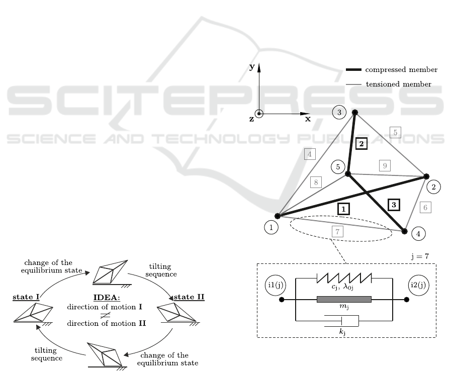
structure. This idea is illustrated in Figure 1.
Figure 1: Supposed behavior of the motion system.
Thus, this approach enables a uniaxial bidirecti-
onal crawling motion with only one actuator using a
selected actuation frequency. Therefore, the presence
of anisotropic friction properties and the application
of high-end actuators is not necessary anymore.
2 MECHANICAL MODEL OF
THE MOTION SYSTEM
2.1 Dynamics of the Multistable
Tensegrity Structure
The tensegrity structure shown in Figure 2 is con-
sidered. This structure consists of 9 members
(j = 1, 2,.. .,9) which are connected in 5 nodes
(i = 1, 2,.. .,5). These nodes are modeled as fricti-
onless revolute joints. With regard to the occurring
stress at the equilibrium state the members are divided
in compressed members and tensioned members. For
the given structural topology, the elements j = 1, 2,3
are classified as compressed members. The members
j = 4, 5,6,7, 8,9 are declared as tensioned members.
Figure 2: Two-dimensional multistable tensegrity structure
and the mechanical model of a single member.
The current configuration of the tensegrity struc-
ture is defined by the position of the nodes i. These
position are evaluated respective to the Cartesian in-
ertial coordinate system {x,y,z} to ~r
i
= (x
i
,y
i
,z
i
)
T
.
Dynamical Investigation of Crawling Motion System based on a Multistable Tensegrity Structure
123

Furthermore, the structure is supposed to be two-
dimensional in the x-y-plane. Therefore, the z-
component of the node positions is identical to zero
(z
i
≡ 0). This yields to a degree of freedom of 10
for the considered tensegrity structure. As generali-
zed coordinates the components of the node positions
x
i
and y
i
are selected. These parameters are combined
in the vector ~q = (x
1
,y
1
,x
2
,y
2
,. .., x
5
,y
5
)
T
.
In order to describe the dynamics of the tensegrity
structure all acting loads have to be specified. The-
refore, the forces as consequence of the deformations
of the members have to be taken into account. The
deformation behavior of a single member is modeled
with a linear spring which is described by the accor-
ding stiffness c
j
and its initial length λ
0,j
. The cor-
responding energy dissipation as consequence of the
material damping properties is given by a linear dam-
per with the damping coefficient k
j
. Furthermore, the
inertia of each element has to be taken into account.
The element j with the mass m
j
is modeled by a linear
link element known from the finite element method.
Therefore, the inertia is given by the according mass
matrix. For the following investigations the mass of
the tensioned members is assumed to be neglectable
(m
j
= 0 for j = 4,5, 6,7,9.) The resulting mechanical
model of a single member of the tensegrity structure
is given by a parallel arrangement of the mentioned
components (see Figure 2). The deformation of the
member j is given by the position of the node i1(j) at
its beginning and the node i2(j) at its end. The corre-
sponding spring force
~
F
c,j
and the damping force
~
F
k,j
are formulated in (1) and (2).
~
F
c,j
= −c
j
(|
~
λ
j
| − λ
0,j
)
~
λ
j
|
~
λ
j
|
,
~
λ
j
=~r
i2(j)
−~r
i1(j)
(1)
~
F
k,j
= −k
j
˙
~
λ
j
·
~
λ
j
|
~
λ
j
|
~
λ
j
|
~
λ
j
|
,
˙
~
λ
j
=
˙
~r
i2(j)
−
˙
~r
i1(j)
(2)
With regard to the topology of the tensegrity struc-
ture these forces are combined to the vectors
~
C(~q) and
~
K(
˙
~q,~q). This approach is shown in (3) and (4).
~
C(~q) = −
−
~
F
c,1
−
~
F
c,4
−
~
F
c,7
−
~
F
c,8
~
F
c,1
−
~
F
c,5
−
~
F
c,6
−
~
F
c,9
−
~
F
c,2
+
~
F
c,4
+
~
F
c,5
−
~
F
c,3
+
~
F
c,6
+
~
F
c,7
~
F
c,2
+
~
F
c,3
+
~
F
c,8
+
~
F
c,9
(3)
~
K(
˙
~q,~q) = −
−
~
F
k,1
−
~
F
k,4
−
~
F
k,7
−
~
F
k,8
~
F
k,1
−
~
F
k,5
−
~
F
k,6
−
~
F
k,9
−
~
F
k,2
+
~
F
k,4
+
~
F
k,5
−
~
F
k,3
+
~
F
k,6
+
~
F
k,7
~
F
k,2
+
~
F
k,3
+
~
F
k,8
+
~
F
k,9
(4)
The inertia of the tensegrity structure is taken into ac-
count by the mass matrix M. Hence, the nonlinear sy-
stem of equations of motion shown in (5) results.
M ¨q +
~
K(
˙
~q,~q) +
~
C(~q) =
~
0 (5)
For the following investigations the parameter values
listed in Table 1 are used.
Table 1: Topology and selected parameter values of the ten-
segrity structure.
El. Nodes λ
0,j
c
j
k
j
m
j
j i1 − i2 [m] [N/m] [Ns/m] [kg]
1 1 − 2 0.10 10
6
0.2 0.1
2 3 − 5 0.02 10
6
0.2 0.02
3 4 − 5 0.02 10
6
0.2 0.02
4 1 − 3 0.02 3000 0.2 0
5 2 − 3 0.02 3000 0.2 0
6 2 − 4 0.02 3000 0.2 0
7 1 − 4 0.02 3000 0.2 0
8 1 − 5 0.01 10000 0.2 0
9 2 − 5 0.01 10000 0.2 0
2.2 Modeling of the Crawling Motion
System
In order to realize a crawling motion an ac-
tuation of the tensegrity structure is required.
For the following investigations free length of
the tensioned member 8 is manipulated by a
harmonic excitation function s(t) = a sin(2π ft)
(a - amplitude of excitation, f - actuation frequency).
The corresponding actuation force is given in (6).
~
F
A
(t) = (c
8
s(t) + k
8
˙s(t))
~
λ
8
|
~
λ
8
|
(6)
The multistable tensegrity structure is in contact with
a horizontal plane due to gravity (~g = −g
~
e
y
). There-
fore, beside the actuation force the equations of mo-
tion have to be completed by the gravitational forces
as well as the contact forces. Moreover, occurring
friction effects at the contact points have to be taken
into account.
The gravitational forces are divided into compo-
nents acting on the nodes i. The resulting force vector
~
G is defined in (7).
~
G = −
g
2
(0,m
1
,0, m
1
,0, m
2
,0, m
3
,0, m
2
+ m
3
)
T
(7)
The contact interface between the nodes i and the
ground is represented by isolated points. The defor-
mation of the ground at those contact points is mo-
delled by a parallel arrangement of a linear damper
ICINCO 2018 - 15th International Conference on Informatics in Control, Automation and Robotics
124

k
g
= 100 Ns/m and a linear spring c
g
= 10
5
N/m.
The deformation of the contact node of the tensegrity
structure is assumed to be neglectable. The corre-
sponding contact force at the node i is given by the
vector
~
F
contact,i
= (F
F,i
,F
N,i
)
T
. The component F
F,i
describes the occurring friction forces at the contact
node i and F
N,i
the acting contact force. The defini-
tion of the component F
N,i
is given in (8).
F
N,i
=
0 if y
i
≥ 0
−c
g
y
i
if y
i
< 0 and
˙
y
i
≥ 0
−c
g
y
i
− k
g
˙
y
i
else
(8)
Occurring friction at the contact nodes are mo-
deled by COULOMB’S LAW OF FRICTION. To mo-
del stiction effects like stick-slip despite of the nu-
merical accuracy the friction model is expanded by
KARNOPP’S METHOD. Therefore, a parameter δ =
10
−4
m/s is introduced. The resulting friction model
is given in (2.2). The static and the dynamic friction
coefficients are given by the parameters µ
0
and µ. The
parameter F
res,i
describes the sum of all acting forces
except the friction force on the node i along the x-axis.
F
F,i
=
−µF
N,i
sign(
˙
x
i
) if |
˙
x
i
| ≥ δ
−µF
N,i
sign(F
res,i
) if |
˙
x
i
| < δ
and |F
res,i
| ≥ µ
0
F
N,i
−F
res,i
else
(9)
All the mentioned components are combined to the
generalized force vector
~
Q(
˙
~q,~q,t). Thus, the nonli-
near system of equation of motion of the entire craw-
ling motion system formulated in (10) results.
M ¨q +
~
K(
˙
~q,~q) +
~
C(~q) =
~
Q(
˙
~q,~q,t) (10)
with
~
Q(
˙
~q,~q,t) =
~
G +
~
F
contact,1
~
F
contact,2
~
F
contact,3
~
F
contact,4
~
F
contact,5
+
−
~
F
A
~
0
~
0
~
0
~
F
A
The resulting mechanical model of the investigated
crawling motion system is illustrated in Figure 3.
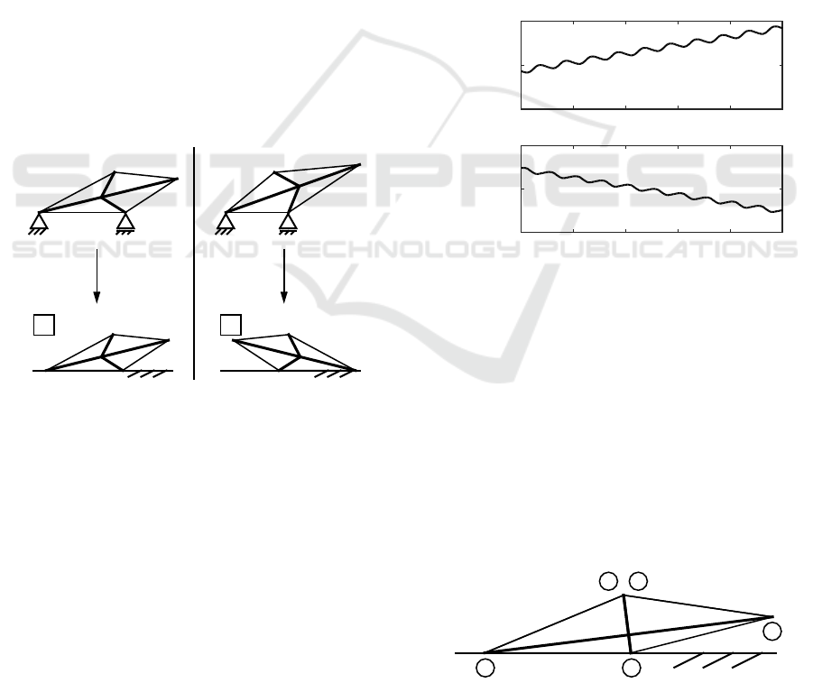
Figure 3: Mechanical model of the crawling motion system
- actuation of tensioned member 8 (two-head arrow), nodes
1 and 4 in contact with ground.
3 SIMULATION OF THE
CRAWLING MOTION
3.1 Initial Conditions of the Crawling
Motion System
The working principle of the crawling motion system
requires two equilibrium states I and II as shown
in Figure 1. These configurations have to differ re-
spective to the corresponding contact nodes. For
the determination of the equilibrium states the non-
actuated motion system (
~
F
A
≡
~
0) is considered for
~q = ~q
eq
and
˙
~q =
~
0. Basing on (10) these conditions
yield to a nonlinear system of equations formulated
in (11).
~
C(~q
eq
) =
~
Q(
~
0,~q
eq
) (11)
However, because of the piecewise smooth con-
tact and friction modelling conventional methods (e.g.
NEWTON-RAPHSON) cannot be applied to calculate
the configuration ~q
eq
and additional numerical effort
is required instead. Therefore, at first the interaction
between the contact nodes and the ground is approxi-
mated by a static support.
Inspired by Figure 1, the nodes 1 and 4 are as-
sumed to be in contact with the ground. The con-
tact is simplified by the supports A and B (see. Fi-
gure 4). The according support reaction are defined
by
~
A = (A
x
,A
y
)
T
and
~
B = (0,B
y
)
T
. This approxima-
tion yields to smooth nonlinear system of equations
given in (12) which can be solved numerically.
~
C(~q
eq
) =
~
G + (
~
A,
~
0,
~
0,
~
B,
~
0)
T
(12)
Each solution of (12) has to be checked additio-
nally (y
2
≥ 0, y
3
≥ 0, y
5
≥ 0). Furthermore, only
stable equilibrium configurations are relevant for the
following investigation. Therefore, the Hessian of the
potential energy is considered. The potential energy
is given in (13).
E =
9
∑
j=1
c
j
2
(|
~
λ
j
|−λ
0,j
)
2
+m
j
g
~r
i1(j)
+~r
i2(j)
2
·
0
1
(13)
Figure 4: Mechanical model of the crawling motion system
for the determination of the relevant stable equilibrium sta-
tes I and II.
Dynamical Investigation of Crawling Motion System based on a Multistable Tensegrity Structure
125
The Hessian of the energy term is evaluated re-
spective to the generalized coordinates ~q. An equili-
brium state is defined as stable if all eigenvalues of the
Hessian are positive. Otherwise, the state is declared
as instable and is not taken into account anymore.
This approach yields to two stable configurati-
ons of the multistable tensegrity structure (see Fi-
gure 5a)). However, finally the support reactions have
to be checked. The y-components of those reactions
have to be positive. Otherwise, the contact between
the node and the ground get lost and a tilting sequence
is initiated. Therefore, and in order to take the given
contact stiffness into account, a dynamical relaxation
of both equilibrium configurations of the system using
(10) with a = 0 and µ
0
= µ = 0 is evaluated. The final
state ~q after the compliance of the break-off-criteria
(|
˙
~q| < 10
−8
m/s and |
¨
~q| < 10
−8
m/s
2
) is declared as
~q
eq
. Indeed, beside the resulting stable equilibrium
state I as consequence of a tilting sequence the stable
equilibrium state II (contact nodes 2 and 4) occurs.
This issue confirmes the idea that changing the equili-
brium state of the tensegrity structure initiates a tilting
sequence of the entire motion system. The resulting
equilibrium configurations I and II of the motion sy-
stem are illustrated in Figure 5b).
x
y
Dynamical
Relaxation
a)
x
y
Dynamical
Relaxation
! Tilting
x
y
b)
I
x
y
II
Figure 5: Stable equilibrium states of multistable tensegrity
structure - a) as result of the mechanical model shown in
Figure 4, b) as result of dynamical relaxation.
This approach was repeated starting from (12) for
other combinations of contact nodes (2 and 4, 1 and
3, 2 and 3). Because of the symmetric topology of
the structure and the selected parameter values equi-
valent results occur. As consequence of the approxi-
mation by static supports two valid stable equilibrium
states are determined. Evaluating a dynamical relax-
ation one of these states yields to a tilting sequence
and the occuring final states ~q
eq
are equivalent to the
states I and II shown in Figure 5b). Without loss of
generality, for the following investigations the state I
corresponds to the contact nodes 1 and 4 (state II cor-
responds to the contact nodes 2 and 4).
3.2 Simulation of the Motion Behavior
The nonlinear system of equations of motion of the
entire motion system is solved numerically using a
RUNGE-KUTTA-METHOD 4
th
ORDER with an appro-
priate step size (∆t = 10
−4
s). As initial condition the
configuration I or II is assumed an the entire system
is supposed to be at rest (
˙
~q(t = 0) =
~
0). The motion
of the system is simulated for 1100 actuation periods.
However, only the steady state solution which is as-
sumed after 1000 actuation periods is evaluated. As
amplitude the value a = 10
−4
m is chosen. Moreo-
ver, the motion is evaluated for different friction pro-
perties. The motion of the system is illustrated ex-
emplarily on Figure 6 to present the qualitative mo-
tion behavior. Moreover, for the considered actuation
frequency and friction properties the different initial
conditions yield to opposite directions of motion.
t [s]
x
1
[m]
10 10.2 10.4 10.6 10.8 11
a)
970
980
990
t [s]
x
1
[m]
10 10.2 10.4 10.6 10.8 11
b)
-1000
-990
-980
Figure 6: Motion behavior for f = 10 Hz, µ
0
= µ = 0.1 and
- a) state I as initial condition, b) state II as initial condition.
However, as consequence of the transient dyn-
amics a change into another equilibrium state III
occurs for several actuation frequencies. For this state
a collision between the compressed member 2 and 3
appears. Moreover, a reverse change into the state I
or II seems to be difficult because of the low potential
energy at this critical state. Therefore, this configura-
tion should be avoided. This configuration is shown
in Figure 7 with the nodes 1 and 5 as contact points.
Because of the symmetry the same configuration will
occur with the contact nodes 2 and 5.
1
2
3
,
4
5
Figure 7: Critical equilibrium state III of the crawling mo-
tion system with nodes 1 and 5 as contact nodes.
ICINCO 2018 - 15th International Conference on Informatics in Control, Automation and Robotics
126
As indicator of the motion behavior the steady
state velocity v of the system is evaluated. This pa-
rameter can be calculated considering the velocity of
the node i (i = 1, 2,3,4, 5) for an actuation period du-
ring the steady state motion. This formula is given in
(14). The parameter t
0
is an arbitrary time instance.
v = f
Z
t
0
+1/ f
t
0
˙
x
i
(t)dt (14)
The results of the steady state velocity for the equili-
brium states I and II as initial condition with different
friction properties are illustrated in Figure 8. The grey
areas represent the frequency ranges which lead to a
change into the critical equilibrium state III as conse-
quence of the transient dynamics.
f [Hz]
v [mm=s]
0 2 4 6 8 10 12 14 16 18 20
-20
-10
0
10
20
a)
initial state: I initial state: II
f [Hz]
v [mm=s]
0 2 4 6 8 10 12 14 16 18 20
-30
-20
-10
0
10
20
30
b)
f [Hz]
v [mm=s]
0 2 4 6 8 10 12 14 16 18 20
-20
-10
0
10
20
c)
Figure 8: Steady state velocity of the crawling motion
system with the different equilibrium configurations as
initial conditions and - a) µ
0
= µ = 0.1, b) µ
0
= µ = 0.2,
c) µ
0
= µ = 0.5.
These results show that for low actuation frequen-
cies ( f < 8 Hz) the motion can be considered as in-
efficient (v < 1 mm/s). For the following frequency
range (8 Hz < f < 9.8 Hz) the critical configuration
occurs as result of the transient dynamics. However,
for actuation frequencies above 10 Hz the results con-
firm the basic idea of this approach. A motion of the
entire system appears as consequence of small oscil-
lations around the stable state I or II. Indeed, the di-
rection of motion can be varied by changing the equi-
librium configuration at the initial state. For the inves-
tigated parameters the use of state I as initial condi-
tion yields to a positive motion (v > 0 mm/s). Assu-
ming the state II as initial condition a negative motion
(v < 0 mm/s) occurs. Therefore, the results confirm
that the multistability of the tensegrity structure can
be utilized to control the direction of motion of a cra-
wling motion system.
The influence of the chosen equilibrium state on
the direction of motion becomes obvious regarding
the corresponding vibration mode of the crawling mo-
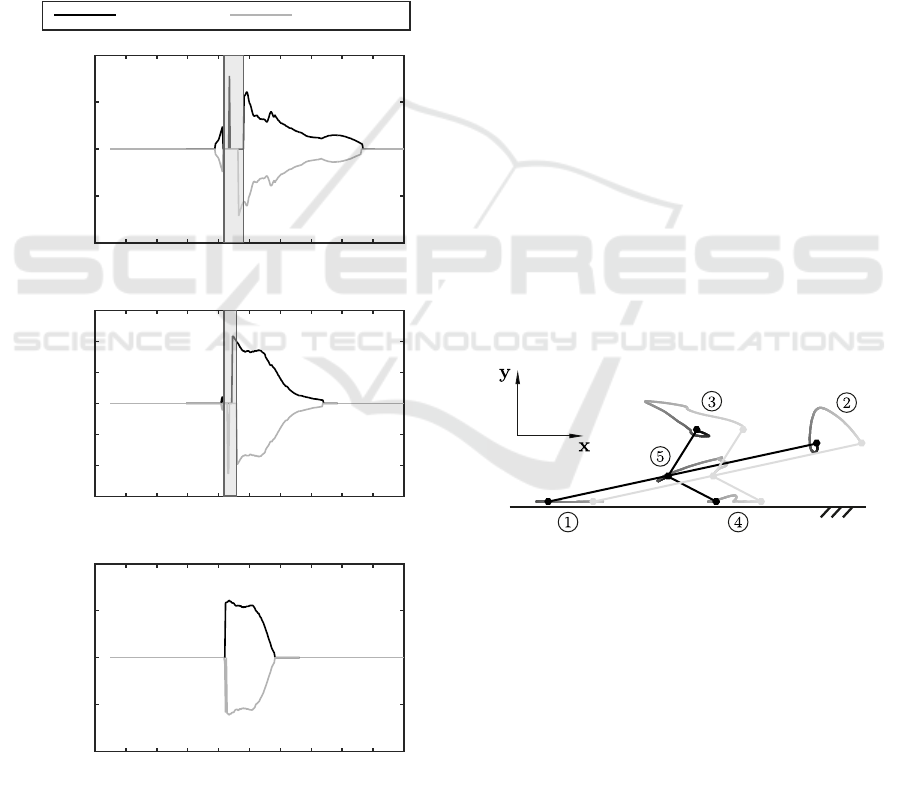
tion system. In Figure 9 the scaled trajectories of the
nodes are exemplarily illustrated. Focusing on the
acting contact points, a partial lifting of node 4 can
be recognized whereas node 1 is permanent in contact
with the horizontal ground. This issue as well as the
different contact forces yield to occurrence of friction
effects which are essential for the motion. Changing
the equilibrium state, a similar effect results. Howe-
ver, the arrangement of the contact nodes is different
which affects the direction of motion.
Figure 9: Scaled trajectories of nodes during one actuation
period (dark → bright) for state I as initial state, f = 10 Hz
and µ
0
= µ = 0.2 - scale: |x|
∗
= 10|x|, |y|
∗
= 2|y|.
3.3 Change of the Equilibrium State
The previous results show that a uniaxial bidirectio-
nal motion of the considered system is possible using
only one actuator. However, the change between the
equilibrium state I and II has not be considered yet.
Of course, different methods and strategies of actuati-
ons are possible to realize the mentioned switch be-
tween these states. But the following investigation
only show that it this change of equilibrium states
is possible for a chosen parameter set. Therefore, as
actuation strategy of the tensioned member 8 a half-
Dynamical Investigation of Crawling Motion System based on a Multistable Tensegrity Structure
127
wave of a sine is selected. The resulting excitation
function u(t) is given in (15).
u(t) =
(
asin(2π f t) if t mod 1/ f ≤ π
0 else
(15)
The resulting actuation force can be calculated by (6)
using u(t) instead of s(t). For the change from state
I into state II the frequency is varied from 10 Hz to
15 Hz and the amplitude from 10
−4
m to 10
−3
m. For
the reverse change of states, the same frequency range
is considered. However the excitation amplitude is
supposed to be in a range from −10
−3
m to −10
−4
m.
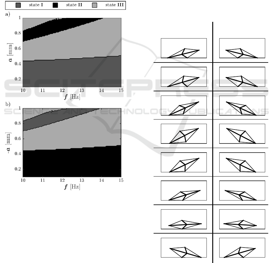
The according results are shown in Figure 10.
Figure 10: Dynamical investigation of the change of
the equilibrium state for a chosen actuation strategy with
µ
0
= µ = 0.1 and - a) state I as initial state, b) state II as
initial state.
These results confirm that a change of the equi-
librium states is possible for the selected actuation
strategy. Therefore, for example the use of only
one actuator with an actuation frequency of 10 Hz
enables a uniaxial forward and backward motion as
well as a change of the equilibrium state (I → II and
II → I) utilizing the emphasized multistability of the
tensegrity structure.
However, these results show that for a significant
parameter range a change into the critical equilibrium
state III occurs. As mentioned in the previous section
a reverse change into another equilibrium state seems
to be difficult. Hence, the occurrence of the critical
state prevents a further use of the motion system. The-
refore, for the construction of a prototype safeguards
which prohibit a change into the critical equilibrium
state III should be taken into account (e.g. mechan-
cial stops).
In order to illustrate the dynamics during the
change of the equilibrium states corresponding con-
figurations at different time instances are displayed
exemplarily in Figure 11. This figure shows that as
consequence of the change of the equilibrium state of
the tensegrity structure a tilting sequence of the entire
locomotion system occurs as supposed in Figure 1.
0 s
a)
I ! II
0:025 s
0:05 s
0:075 s
0:1 s
0:125 s
0:15 s
0:175 s
b)
II ! I
Figure 11: States during the change of the configurations for
µ
0
= µ = 0.1 and f = 10 Hz a = 0.8 mm, b) a = −0.8 mm.
ICINCO 2018 - 15th International Conference on Informatics in Control, Automation and Robotics
128

4 CONCLUSIONS
This paper deals with the use of a multistable compli-
ant tensegrity structure for the application in a craw-
ling motion system. Most of the known crawling mo-
tion system allow only a one-way motion or requires
advanced demands to the operating actuator in order
to realize a bidirectional uniaxial motion. In this pa-
per a crawling motion system basing on a multistable
tensegrity structure is modeled. The tensegrity struc-
ture enables multiple stable equilibrium configurati-
ons and is in contact to horizontal plane due to gravity.
As consequence of the acting gravitational forces the
application of certain equilibrium states initiates a til-
ting sequence. Hence, the mode of the entire motion
system is changing. Moreover, total different dynami-
cal properties result for the identical actuation of the
system. Transient simulations are evaluated for se-
lected parameter values of the tensegrity structure and
the steady state solution which assumed after 1000
actuation periods is considered. The motion behavior
which is characterized by the steady state velocity is
analyzed for the different equilibrium configurations
as initial state and diverse friction properties. The re-
sults confirm that a feasible control of the direction
of motion occurs utilizing the given multistability of
the tensegrity structure. At total, these investigations
show that, indeed, a bidirectional uniaxial motion can
be realized by the use of only one actuator with a se-
lected excitation frequency.
However, for a significant parameter range a
change into an additional equilibrium state occurs.
Because of the corresponding low potential energy,
a reverse change into another equilibrium state seems
to be difficult. Hence, after the occurrence of this cri-
tical state the motion system cannot be used anymore.
Therefore, a prototype should be equipped with safe-
guards like mechanical stops which prohibt a change
into that critical equilibrium state.
Moreover, the authors target the development of a
prototype as well as the experimental validation of the
theoretical results shown in this paper.
ACKNOWLEDGEMENTS
This work is supported by the Deutsche Forschungs-
gemeinschaft (DFG project BO4114/2-1).
REFERENCES
B
¨
ohm, V., Sumi, S., Kaufhold, T., et al. (2017). Compli-
ant multistable tensegrity structures. Mechanism and
Machine Theory, 115:130 – 148.
B
¨
ohm, V., Zeidis, I., and Zimmermann, K. (2013). Dyn-
amic analysis of a simple planar tensegrity structure
for the use in vibration driven locomotion systems. In
12th Conference on Dynamical Systems - Theory and
Applications, pages 341–352.
B
¨
ohm, V., Zeidis, I., and Zimmermann, K. (2015). An ap-
proach to the dynamics and control of a planar ten-
segrity structure with application in locomotion sys-
tems. International Journal of Dynamics and Control,
3(1):41–49.
B
¨
ohm, V. and Zimmermann, K. (2013). Vibration-driven
mobile robots based on single actuated tensegrity
structures. In 2013 IEEE International Conference on
Robotics and Automation, pages 5475–5480.
Bolotnik, N., Zeidis, I., Zimmermann, K., et al. (2006). Dy-
namics of controlled motion of vibration-driven sys-
tems. Journal of Computer and Systems Sciences In-
ternational, 45(5):831–840.
Chen, L. H., Kim, K., Tang, E., et al. (2017). Soft spherical
tensegrity robot design using rod-centered actuation
and control. Journal of Mechanisms and Robotics,
9(2):025001–025001–9.
Fang, H.-B. and Xu, J. (2011). Dynamic analysis and op-
timization of a three-phase control mode of a mobile
system with an internal mass. Journal of Vibration
and Control, 17(1):19–26.
Fang, H.-B. and Xu, J. (2012). Controlled motion of a
two-module vibration-driven system induced by inter-
nal acceleration-controlled masses. Archive of Applied
Mechanics, 82(4):461–47.
Hustig-Schultz, D., SunSpiral, V., and Teodorescu, M.
(2016). Morphological design for controlled tense-
grity quadruped locomotion. In 2016 IEEE/RSJ In-
ternational Conference on Intelligent Robots and Sys-
tems (IROS), pages 4714–4719.
Khazanov, M., Jocque, J., and Rieffel, J. (2014). Evolution
of locomotion on a physical tensegrity robot. 14th In-
ternational Conference on the Synthesis and Simula-
tion of Living Systems, pages 232–238.
Kim, K., Chen, L. H., Cera, B., et al. (2016). Hopping and
rolling locomotion with spherical tensegrity robots. In
2016 IEEE/RSJ International Conference on Intelli-
gent Robots and Systems (IROS), pages 4369–4376.
Liu, H., Yu, Y., Sun, P., et al. (2016). Motion analysis of the
four-bar tensegrity robot. In 2016 IEEE International
Conference on Mechatronics and Automation, pages
1483–1488.
Rieffel, J. A., Valer-Cuevas, F. J., and Lipson, H. (2010).
Morphological communication: exploiting coupled
dynamics in a complex mechanical structure to
achieve locomotion. Journal of the Royal Society In-
terface, 7(45):613–621.
Sabelhaus, A. P., Bruce, J., Caluwaerts, K., et al. (2015).
System design and locomotion of superball, an untet-
hered tensegrity robot. In 2015 IEEE International
Conference on Robotics and Automation (ICRA), pa-
ges 2867–2873.
Schorr, P., Sumi, S., B
¨
ohm, V., et al. (2017). Dynamical
investigation of a vibration driven locomotion system
Dynamical Investigation of Crawling Motion System based on a Multistable Tensegrity Structure
129

based on a multistable tensegrity structure. In 14th
Conference on Dynamical Systems - Theory and Ap-
plications, pages 485–496.
Steigenberger, J. and Behn, C. (2012). Worm-Like Locomo-
tion Systems. An intermediate theoretical Approach.
De Gruyter Oldenbourg.
Sumi, S., B
¨
ohm, V., and Zimmermann, K. (2017). A mul-
tistable tensegrity structure with a gripper application.
Mechanism and Machine Theory, 114:204 – 217.
Tietz, B. R., Carnahan, R. W., Bachmann, R. J., et al.
(2013). Tetraspine: Robust terrain handling on a ten-
segrity robot using central pattern generators. In 2013
IEEE/ASME International Conference on Advanced
Intelligent Mechatronics, pages 261–267.
Zimmermann, K., Zeidis, I., and Behn, C. (2009a). Mecha-
nics of Terrestrial Locomotion with a Focus on Non-
pedal Motion Systems. Springer.
Zimmermann, K., Zeidis, I., Bolotnik, N., et al. (2009b).
Dynamics of a two-module vibration-driven system
moving along a rough horizontal plane. Multibody Sy-
stem Dynamics, 22(2):199–219.
Zimmermann, K., Zeidis, I., and Pivovarov, M. (2013). Dy-
namics of two interconnected mass points in a resis-
tive medium. Differential Equations and Dynamical
Systems, 21(1):21–28.
ICINCO 2018 - 15th International Conference on Informatics in Control, Automation and Robotics
130
