
Analysis of Under-Actuated Snake Arm Robot
Xiaoqi Zhou, Feng Wang, Lei Dong and Zhongjian Dai
School of Automation, Beijing Institute of Technology, Beijing
ZXQ9283@163.com
Keywords: Ssnake arm robot, under-actuated structure, modeling analysis, error analysis.
Abstract: In view of the problem that traditional industrial robot can’t adapt to some special areas due to its structural
characteristics,a wire -driven snake arm robot, consisting of joints, drive mechanisms and a sliding rail
platform is designed. In this paper, the structure characteristics of discrete series robot are analyzed in detail
comparing with continuum robot. Moreover, the kinematic modeling of the under-actuated snake arm robot
is established by using the method of continuum robot. Through simulation of the length of drawing wires,
the relationships between the length of the wires and the bending angles and angles of joint rotation are
obtained. The correctness and effectiveness of the robot are proved by analyzing and discussing the error
factors of modeling and the attitude control experiments of the robot based on the space model.
1 INTRODUCTION
At present, when operation in some special fields and
nonstructural environments, high requirements of
robots for flexibility and the deformability to adapt to
the environment are brought forward. Traditional
robots fail to accomplish such work limited by size of
joints and degrees of freedom (DOF), while continuum
robots become a hot spot in recent research.
Continuum robots achieves many developments and
fruits by combining bionics, for instance, excellent
compliance of elephant trunk robot or soft tentacle
robot also shows the prospect and value of application
of continuum robot in directions such as human-
machine interface, grasping of complex fragile article
and operation in confined space. On the other hand,
however, infinite DOF of continuum robot brings the
problems of difficulty in precise control, increasing of
coupling and limited loading capacity resulting from
insufficient rigidity. Comparatively, though
compliance and DOF of discrete joints series
manipulator decrease somewhat, its rigidity becomes
better, and on the other hand, its discrete joints series
construction increases the ability to locally control
interested location. What’s more, coordinates change
between joints can control the spatial position of
terminal actuator more accurately.
In fact, discrete serial construction is also
embodied widely in biology field. The backbone
construction of vertebrate represented by snake is the
discrete serial model which ensures both good rigid
support and flexibility of movement due to hyper
degrees of freedom resulting from multi joint series.
Both continuum and discrete multi joints robots
have been studied and explored by many scholars at
home and abroad. In paper (2010), Hu Haiyan et al.
made analysis and description of mathematical model
of a kind of continuum robots supported by flexible
rod, and now the description of continuum robot
kinematics in the literature adopts the method of
correlating the drive space, workspace of the joints and
operating space of the actuator which is accepted by
most scholars. In recent years, some scholars start from
bionics by focusing on description of movement
mechanism of continuous body creature in the nature
and attempt to find effective methods of movement
control by imitating the movement models of
continuous body creature. For example, paper
(Cianchetti, 2011) to (Germán Sumbre, 2005)
researched the motion mechanism of octopus tentacle,
but the structure of the tentacles in the continuum form
is simplified as piecewise discrete model which cannot
effectively and truly restores the movement of natural
organisms. For discrete serial construction, paper
(G. Dogangil, 2010) proposed a method based on
geometrically mirroring model for a kind of discrete
under-actuated snake arm robot, calculating the
relation between drive wires and the motion of joints,
414
Zhou, X., Wang, F., Dong, L. and Dai, Z.
Analysis of Under-Actuated Snake Arm Robot.
In 3rd International Conference on Electromechanical Control Technology and Transportation (ICECTT 2018), pages 414-422
ISBN: 978-989-758-312-4
Copyright © 2018 by SCITEPRESS – Science and Technology Publications, Lda. All rights reserved
coupling relation between every joint in detail,
however, the process and calculation are too complex,
and no effective experimental verification is given.
As mentioned above, continuum and discrete multi
joints robots have their own advantages, but few
literature analyzed ontology characteristics of discrete
serial robot in depth and detail. With the discrete
under-actuated snake arm robot as subject, this paper
analyzes movement and structure features of this kind
of robot in detail. Meanwhile by referencing the
modeling of continuum robot, the kinematic model of
the robot is established and the modeling error is
analyzed. Finally an experiment is conducted to test
modeling of discrete under-actuated snake arm robot
and control the gesture of robot based on space model.
2 STRUCTURE
CHARACTERISTICS OF
UNDER-ACTUATED SNAKE
ARM ROBOT
In some cases, operators hope to improve flexibility of
motion of multi-joint robot to meet operational
demand while not add actuators so that they don’t have
to increase the cost and power consumption of robot,
and the introduction of under-actuated joints is a good
solution to this contradiction. For description
convenience, the wire-driven controlled joint is called
active joint later in the paper, while the under-actuated
joint is called driven joint. Under-actuated snake arm
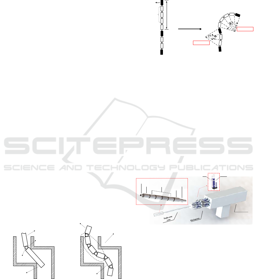
robot has two major advantages: firstly, compared to
full drive construction, it can increase the compliance
of local movement, the effect is shown in Fig. 1.The
improvement of the local bending capacity is
especially suitable for the operating requirements in
confined spaces such as the detection of bent pipes.
1st joint
2nd joint
ball bearing
driving wire
1st joint(active joint)
2nd joint
(active joint)
driven joints
Figure 1. Performance comparison of under-drive structure
Secondly, the reconfiguration is enhanced. The
driven joint can be added or removed flexibly within
the controllable range of deformation. On one hand,
effective operating length of robot can be changed
flexibly, on the other hand through combination of
different numbers of driven joints in different region,
different bending deformation can be generated to
increase movement variation capability of interested
location, as shown in Fig. 2.
Gesture transformation
Active joint
Driven
joint
A motion unit
Φ1=5θ
Φ2=3θ
Figure 2. Reconfiguration of under-driven structure
Accordingly, within the range where degrees of
freedom and the length of snake arm robot are
controllable, through adding driven joints
appropriately to form the under-actuated body, it can
avoid adding actuators while improving movement
compliance of the manipulator. It is an effective
method to increase the operating capacity of joints
series construction.
3 MECHANICAL STRUCTURE
The system of under-actuated snake arm robot is
shown in Fig. 3, which includes snake arm joint, drive
mechanism and slide movable platform.
Slide movable
platform
Hollow hose
Drive wire
Active joint 1
Driven joint
Active joint 2
Displacement sensor
Electric putter
Figure 3. Under-actuated snake arm robot system
Drive mechanism of typical wire-driven is post
positioned separated from the robot joints, only the
drive wires or micro sensors are at the joint, and all
drivers are integrated and put behind the joint body.
On one hand ,weight of robot joint can be reduced
dramatically to ensure its flexibility of movement;
secondly, long effective operating length or good
loading capacity of robot can be ensured; and thirdly,
when operating in high corrosion or dangerous
environment, all electrical components don’t contact
internal operating environment directly, so the safety
can be ensured. Drive device has many structures and
realization forms, most of which are not fixed but
Analysis of Under-Actuated Snake Arm Robot
415
installed on movable platform. In addition to slide type
shown in fig. 3, the movable platform can also be
replaced with other types such as AGV, industrial
robot. The mainly functioning of movable platform is
to support movement of snake arm robot to realize
large displacement of robot within certain space range,
enabling the robot to reach working point quickly.
Drive mechanism consists of parallel joint
actuators of snake arm robot, parallel arrangement of
drivers simplifies the size of drive mechanism, reduces
the coupling influence between every sub-driver. Thus
the construction of serial joint and parallel drive is also
one of structural features of such snake arm robot.
Single joint driver consists of the electric putter with
maximum thrust of 2,000N and displacement sensor.
Joint body consists of active joints, driven joints
and ball bearings. Each group of motion unit includes
one active joint and four driven joints which are
connected through ball bearing, realizing spatial
rotation. The joint and spherical are hollow
construction, flexible hollow hose goes through the
whole joint body forming the “framework” of robot,
playing the role of support and limit setting.
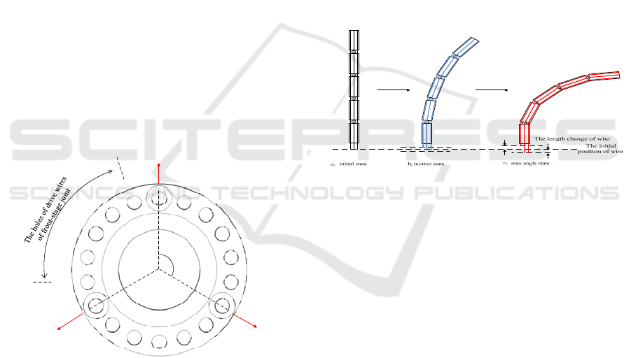
Every active joint is driven by three wires
distributing at even interval of 120°, and the driven
joint is not driven directly by wire, and the wire hole
of active joint distribution is shown in Fig. 4.
The i active joint
Drive wire
Li1
Drive wire
Li2
Drive wire
Li3
120°
L
(i-1)1
L
(i-2)1
L
(i-3)1
L
(i-4)1
L
(i-5)1
L
(i-1)2
L
(i-2)2
L
(i-3)2
L
(i-4)2
L
(i-5)2
L
(i-1)3
L
(i-2)3
L
(i-3)3
L
(i-4)3
L
(i-5)3
Figure 4. The schematic of hole distribution of the i-th
active joint
Apparently, more rear the joint is at, more wires it
will be passed through, because in addition to three
wires driving current joint, wires of front every joint
will pass through. In order to minimize coupling of
movement between every joint, when the wires of
front-stage joint reach concentric position of rear
stage, they need to be arranged by staggering for
certain angle for joints at adjacent stages.
4 MODELING ANALYSIS
Modeling of wire type under-actuated snake arm robot
can reference the method of continuous robot. There
are two reasons. First, adding a hollow hose in
construction will make circuit easier to track. Besides,
it also has function of elastic support and position
restriction. This makes every part of robot joint move
approximately to constant curvature bending as
possible. In addition, by analyzing the morphology of
robot at three different moments as shown in Fig. 5, it
can be found that, at initial state a, all joint drive wires
are in stretching state with physical feature of snake
arm robot under discrete construction identical to that
of continuum robot. Through state b to state c, the joint
rotates to the maximum angle when the wire is at
maximum bending. Infinitesimal method is used to
make analysis of the movement, thus in unit time the
model unit of discrete robot can be equivalent to
continuum robot.
Figure 5. Three morphological changes of the snake arm
robot
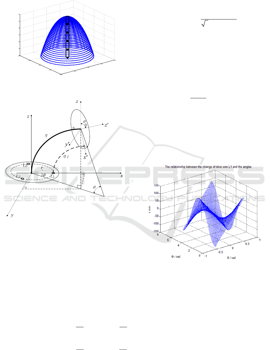
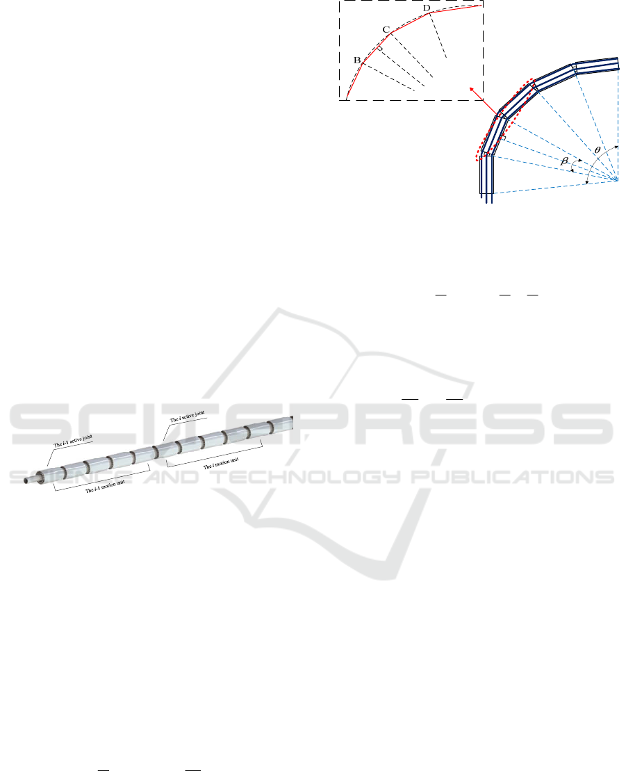
4.1 Kinematic Model
During movement of snake arm robot, bending angle
θ and rotary angle Φ of a group of motion unit are
realized by controlling the length of three pieces of
evenly spaced drive wires of active joint. The
operating space is shown in Fig. 6. If discrete joints of
this group of motion unit are regarded as a section of
continuous body, morphology variation of next group
of motion unit driven by the wire is shown in Fig. 7.
ICECTT 2018 - 3rd International Conference on Electromechanical Control Technology and Transportation
416
-200
-100
0
100
20 0
-200
-100
0
10 0
20 0
27 0
28 0
29 0
30 0
31 0
32 0
33 0
z mm
x mm
y mm
Operating space of one motion joint
Figure 6. Operating space of one motion joint
Figure 7. The attitude change of a set of motion unit under
continuous form
Assuming that the original length of the three drive
wires is l, and the length of motion units after driving
are changed to
1
l ,
2
l and
3
l respectively, while length
variation of drive wire is expressed as
i
L
(i=1,2,3),and the circumference radius of the driving
wire through hole is r (in this paper,r=1.25cm). From
Fig. 7 the relation between
i
L and bending angle θ,
rotary angle Φ is obtained as shown in equation 1 to 3,
where θ is valued [-30°,30°], Φ is valued [0°,360°]:
11 1
L()coscosll r
(1)
22 2
22
L()cos cos
33
ll r
(
)
()
(2)
33 3
44
L()cos cos
33
ll r
(
)
()
(3)
The relationship between the rotary angle Φ and
the change of the wire length can be solved from (2)
and (3):
23
23
arctan
3( )
LL
LL
(4)
Within [0,2π], Φ will contain two solutions with a
different value of π. If using
x axis as starting axis, with
counterclockwise direction as positive direction, it can
be analyzed through equation (1) that when
1
L <0, Φ
takes the solution within [π/2
,3π/2]; when
1
L >0, Φ
takes the solution within [0
, π/2] or (3π/2 , 2π].
Bending angle θ of motion unit can be obtained by the
following equation:
cosr
l
1
(5)
Through equation (1) to (5) we obtained the
mapping relation between movement space and drive
space of the joints, and the state of the other variable
can be obtained through any variation of either known
angle or known wire length. Through simulation the
relation between variation of length
1
L of drive wire,
bending angle and rotary angle is obtained as shown in
Fig. 8.
Figure 8. While θ=[-30°,30°] Φ=[0°,360°],the curve
diagram of the length change of drive wire
1
L
If keep rotary angle constant (in simulation with
Φ=0°as an example), when bending angle varies
continuously, the relation between length variation of
3 wires is shown in Fig. 9. It is a linear variation with
a certain slope. When bending angle keeps constant (in
simulation with Φ=30°as an example), when rotary
angle varies continuously ([0,2π]), the relation
between length variation of 3 wires is shown in Fig.
10. When bending angle and rotary angle both vary
continuously, by combining results of Fig. 9 and
Fig.10 we can obtain the “isogonal line” (Fig. 11) of 3
Analysis of Under-Actuated Snake Arm Robot
417
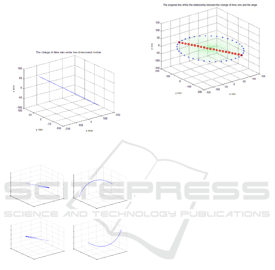
drive wires. In the figure, a straight line drawn along
any slope represents the relation between continuously
varying bending angle and the variation of the wire
under a given rotary angle. While the line is in different
circular lines, it represents the relation between
continuously varying rotary angle and the variation of
the wire under a given bending angle.
Figure 9. While Φ=0°,θ=[-30°,30°],the relationship of
the length change of 3 drive wires
0
50
100
150
-140
-120
-100
-80
-60
-100
-50
0
50
10 0
15 0
z1 mm
The relationship between the change of drive wire L1 a nd the angle,
φ
=[0,90]
x1 mm
y1 mm
-150
-100
-50
0
50
-200
-100
0
10 0
60
80
10 0
12 0
14 0
z2 mm
The relationship between the change of drive wire L1 and the angle,
φ
=(90,180]
x2 mm
y2 mm
-150
-100
-50
0
60
80
10 0
12 0
140
-150
-100
-50
0
50
100
z3 mm
The relation ship between th e chang e of driv e wire L1 and the angle,
φ
=(180,27 0]
x3 mm
y3 mm
-50
0
50
10 0
150
-100
0
10 0
20 0
-140
-120
-100
-80
-60
z4 mm
The relationship between the change of drive wire L1 and the angle,
φ
=(270,36 0]
x4 mm
y4 mm
Figure 10. While θ=30° Φ=[0°,360°], the relationship of the
length change of 3 drive wires
Figure 11. While θ=[-30°,30°] Φ=[0°,360°],the “isogonal
line” relationship of the length change of 3 drive wires
In fact, because every group of motion unit consists
of several serial joints, when we obtain the varied
angle, we can more accurately subdivide the spatial
position in a group of motion unit. In other words,
compared to true continuous construction, more
accurate spatial position of robot can be obtained under
discrete series type construction. Because two adjacent
joints are connected only through ball-joint without
other link rod construction of unit length, coordinate
transformation between two adjacent joints can be
obtained only through rotation calculation. If the
coordinate of snake arm robot base is defined, and the
bending angle and rotary angle of robot are obtained,
we can obtain the spatial position of any joint through
matrix transformation between two adjacent joints.
The rotation matrix between two adjacent joints is:
22
22
T
i
cc s scc sc sc
s
cc sc s c c ss
sc ss c
(6)
Where s stands for sin, c stands for cos, Φ is the
rotation angle to the x-axis and the θ is the bending
angle to
z axis.
On the other hand, there will be mutual coupling in
the movement of joints of snake arm robot, and the
movement coupling originates from layer-by-layer
superposition of drive wires. Namely, the drive wire of
former stage (suppose that the first stage motion unit
close to end-effector is set as stage 1) will always reach
the drive mechanism through the latter stage joint. So,
when driving the latter stage joint (for example, No. i
stage motion unit), the drive wire of its No. i-1, i-2 ...
till No. 1 section joint will be all influenced by
coupling. We only need to analyze the coupling
relation of wires when two adjacent stage active joints
move, and the movement coupling of other more
ICECTT 2018 - 3rd International Conference on Electromechanical Control Technology and Transportation
418
stages of joints is only overlapping on the basis.
Taking the movement unit of the i-1 and the i as
examples, as shown in the figure12, the movement of
stage i-1 motion unit does not influence stage i, but the
movement of stage i motion unit can influence length
variation of stage i-d wire, the angle difference of drive
wire of two adjacent active joint concentric hole
position is
/9
, so when stage i motion unit acts,
coupling variation of 3 stage i-1 drive wires is:
(1)1
(1)2
(1)3
cos( / 9)
cos( 7 / 9)
cos( 13 / 9)
iii
iii
iii
Lr
Lr
Lr
(7)
Consequently, when stage i-1 motion unit is driven,
the length variation of its 3 drive wires shall overlay
the coupling variation resulting from movement of
stage i motion unit on the basis of their respective
theoretical calculated value.
It is worth mentioning that using some effective
control methods such as tip-following (the movement
of the next level of motion unit follows the action of
the previous one) can greatly reduce the movement
coupling between motion units so as to improve the
flexibility of movement.
Figure 12. Two levels motion units
4.2 Model Error
The model error of the discrete under-actuated snake
arm robot is mainly due to the fact that the driving
cable is regarded as constant curvature when
modeling,while the drive wire are typically in the form
of multi-segment fold line in practice. So there is error
between models of curve and fold line.
Assuming that at bending angle θ the drive wire of
robot single joint section bends into a fold line
consisting of n sections of straight line, as shown in the
figure 13. And the length of every section of fold line
can be obtained by the following equation:
/)
2
sin(2/)
2
sin(2
''
l
n
ls
(8)
Where
is the bending angle corresponding to
single section of fold line, l is the arc length when the
shape of drive wire bending is an ideal arc.
Figure 13. diagram of multiple poly lines
The total error of the length of a single drive line is
derived from the following equation:
)sin()/sin(
''''
n
n
ll
n
nlsle
n
j
i
2
2
1
2
2
1
(9)
In this paper, the snakelike robot has six sets of
motion units, so the maximum number of broken lines
is 30, and the maximum bending angle is
. In this
case, there is a maximum error:
''
max
007.0)
60
sin
60
1( lle
(10)
From this we can see that, when we consider the
drive line at back of the driven joint as arc of even
curvature, the maximum error between the line length
and the length of the actual multi segment line is about
7
‰, and this error is within our acceptable range.
Moreover, each joint of snakelike robot is controlled
independently. Thus the error of wire will not
accumulate. So it's valid to assume that the line
between the two active joints is arc.
5 EXPERIMENTS AND RESULTS
Freescale DSP 56F8037 is adopted as the control chip
in the arm robot. The displacement sensor of drive wire
is KTC bar type electronic rule. The data collected by
the displacement sensor are filtered by Kalman filter to
remove the White Noise.
The displacement sensor is calibrated, and the
length change of the displacement sensor and the
measured data is shown in the table.Table 1 calibration
data of displacement sensor.
Analysis of Under-Actuated Snake Arm Robot
419
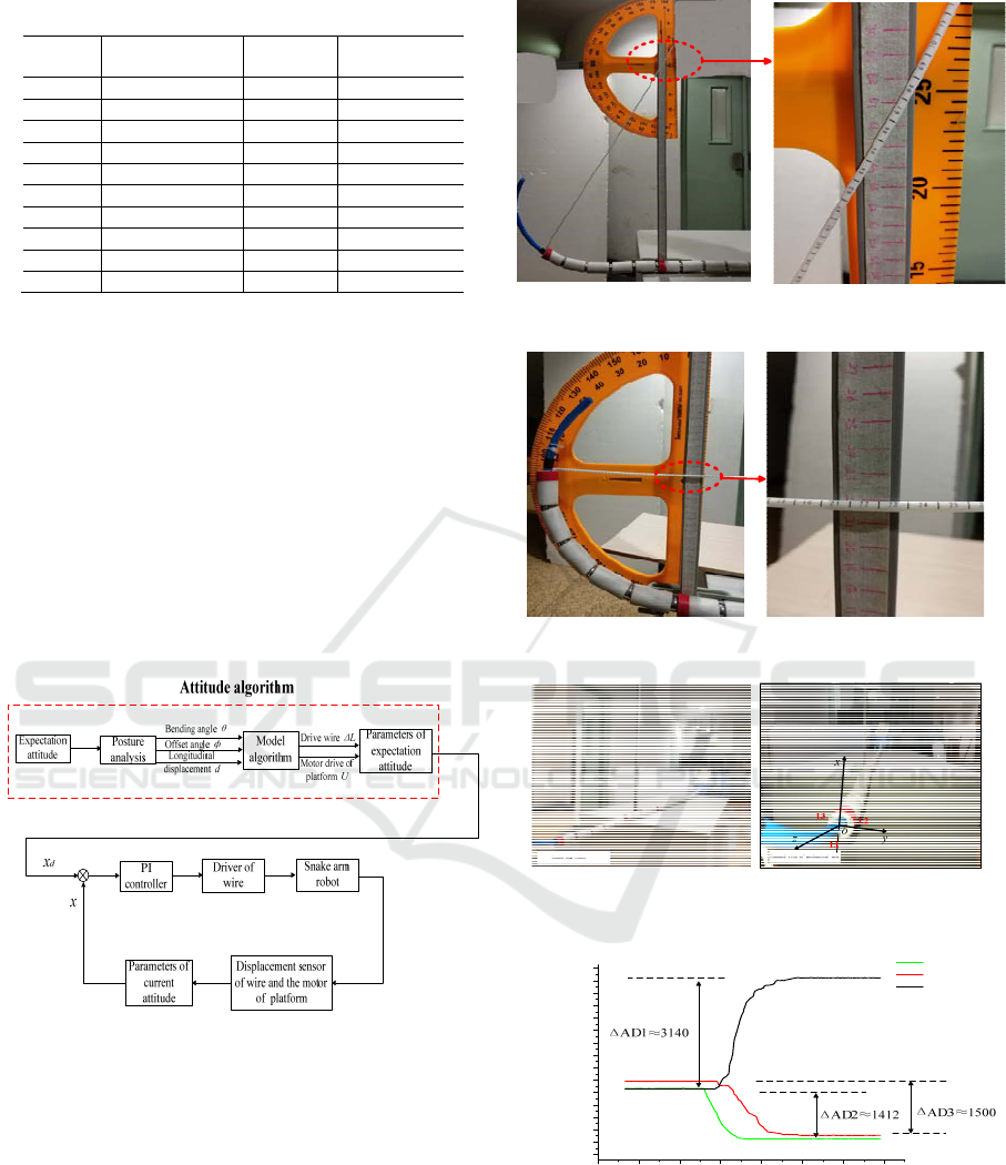
Table 1. calibration data of displacement sensor
length
/cm
AD sample
mean
length
/cm
AD sample
mean
0 133 5 7544
0.5 612 5.5 8319
1 1432 6 9088
1.5 2216 6.5 9863
2 2976 7 10721
2.5 3711 7.5 11494
3 4442 8 12369
3.5 5209 8.5 13215
4 5977 9 14071
4.5 6754 9.5 15066
Starting from the initial 0cm, we recorded the
filtered AD sampling value twice at each 0.5cm
progressive of displacement sensor and got the
average. The AD sampling difference of each 0.5cm is
calculated respectively, then remove the value under
initial length and the maximum length of the larger
fluctuations, add the remaining AD difference and take
the average, finally the relationship between the actual
length variation of the displacement sensor and the
sampling value of AD can be determined: for each
change of 0.5cm, the change of AD sampling value is
about 792.
For the control of the snake arm robot, the PI
control law is adopted, and the control structure block
diagram is shown in the figure 14.
Figure 14. control structure of attitude control of snake arm
robot
A set of motion units of the robot arm is measured
experimentally, and the experimental results and the
curves of the length of the drive wire are shown in the
figure.
Figure 15. Mechanical arm 30 degree bending test
Figure 16. Mechanical arm 90 degree bending test
Figure 17. Manipulator coordinate
0 2 4 6 8 10 12 14
6650
7000
7350
7700
8050
8400
8750
9100
9450
9800
10150
10500
10850
11200
11550
11900
wire 2
wire 3
wire 1
AD sampling value of sensor
time/ms
Figure 18. Change curves of driving lines when bending 90
degrees
When the bending is 90 degrees, according to the
formula given in the previous paper, the theoretical
calculation value of the length change of the three
ICECTT 2018 - 3rd International Conference on Electromechanical Control Technology and Transportation
420
driving wires is respectively: ΔL1=1.96cm,
ΔL2=ΔL3=-0.98cm(the reference coordinate system is
shown in Figure 17 ). The change curves of actual
length of driving wires are shown in Figure 18, and the
errors of L1, L2, L3 are respectively 1%, 9.2%, 3.5%.
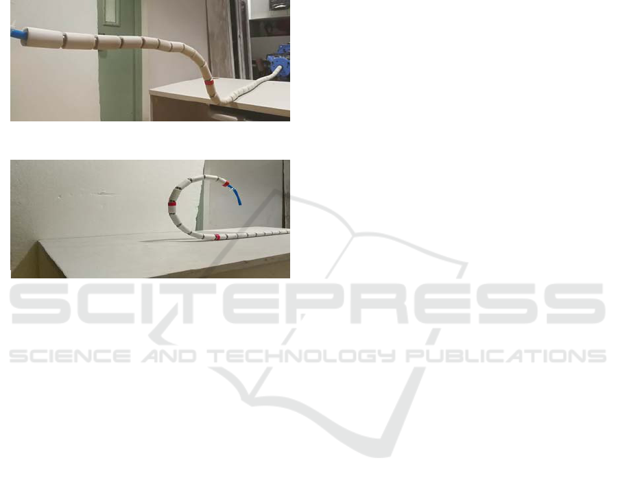
The control effects of S curve attitude and
compliant bending attitude of manipulator is shown in
this paper.
Figure19. S curve attitude
Soft bending control
Figure 20. Bending attitude
6 CONCLUSIONS
In this paper, we discussed and analyzed series snake
arm robot with wire-driven, under-actuated and multi
degrees of freedom under discrete structure.
Specifically, the characteristics and differences of
discrete joint snake arm manipulator, traditional rigid
robot and continuum robot are analyzed, and the
structural characteristics and application advantages of
discrete robot are discussed. In addition, based on the
modeling method of continuum robot, modeling
analysis and error analysis of a ball-connected snake
arm robot are carried out, and the "Isometric" change
diagram relationship between the space angle and the
drive wire of robot is obtained. Finally, through the
closed-loop attitude control, the attitude and deflection
angle of the snake arm robot are controlled effectively
.
REFERENCES
HU Haiyan, WANG Pengfei, SUN Lining, ZHAO Bo, LI
Mantian. Kinematic Analysis and Simulation for Wire-
driven Continuum Robot [J]. JOURNAL OF
MECHANICAL ENGINEERIN,2010,46(19):1-8.
Cianchetti, M., Arienti, A., Follador, M., Mazzolai, B., Dario,
P., & Laschi, C. (2011). Design concept and validation of
a robotic arm inspired by the octopus. Materials Science
& Engineering: C, 31(6), 1230-1239.
Kang, R., Branson, D. T., Guglielmino, E., & Caldwell, D.
G. (2012). Dynamic modeling and control of an octopus
inspired multiple continuum arm robot. Computers &
Mathematics With Applications, 64(5), 1004-1016.
relli M, Renda F, Calisti M, et al. Learning the inverse
kinetics of an octopus-like manipulator in three-
dimensional space. Bioinspir
Biomim. 2015;10(3):035006.
Germán Sumbre, Fiorito, G., Flash, T., & Hochner, B. (2005).
Neurobiology: Motion control of flexible octopus
arms. Nature, 433(7026), 595-596.
G. Dogangil, B. Davies, F.R. y Baena. A review of medical
robotics for minimally invasive soft tissue surgery Proc.
Ins. Mech. Eng. Part H, 224 (5) (2010), pp. 653-679
YUAN Wei, WEI Zhiqiang, ZOU Fang, YAO Yanbin.
Kinematical Analysis of an Underactuated Snake arm
Robot[J].Machinery&Electronics,2014,(11):65-67,68.
Dong, X., Raffles, M., Guzman, S. C., Axinte, D., & Kell, J.
(2014). Design and analysis of a family of snake arm
robots connected by compliant joints. Mechanism &
Machine Theory, 7773-91.
Hannan MW, Walker ID. Kinematics and the
implementation of an elephant's trunk manipulator and
other continuum style robots. J Robot Syst. 2003
Feb;20(2) 45-63. PMID: 14983840.
Zheng Li,Ruxu Du. Design and Analysis of a Bio-Inspired
Wire -driven Multi-Section Flexible Robot. International
Journal of
Advanced Robotic Systems 2013 Vol.10 1729-8806.
Laschi C., Mazzolai B., el. “Design of a biomimetic robotic
octopus am”, Bioinspiration & Biomimetics, vol.
4, 2009 015006.
Bajo A., and Simaan N., “Finding Lost Wrenches: Using
Continuum Robots for Contact Detection and Estimation
of Contact Location”, 2010 IEEE International
Conference on Robotics and Automation, Anchorage,
Alaska, May, 2010, pp. 3666–3673
Y.-J. Kim, S. Cheng, S. Kim, K. IagnemmaDesign of a
tubular snake arm manipulator with stiffening capability
by layer jamming. 2012 IEEE/RSJ International
Conference on Intelligent Robots and Systems, October
7–12, 2012. Vilamoura, Algarve, Portugal, IEEE (2012),
pp. 4251-4256
Li, Z., Ren, H., Chiu, P. Y., Du, R., & Yu, H. (2016). A novel
constrained wire -driven flexible mechanism and its
kinematic analysis. Mechanism & Machine
Theory, 9559-75.
R.J. Webster, B.A. JonesDesign and kinematic modeling of
constant curvature continuum robots: a review. Int. J.
Robot. Res., 000 (00) (2010), pp. 1-22
Han Yuan, Zheng Li, Workspace analysis of wire-driven
continuum manipulators based on static model, Robotics
and Computer-Integrated Manufacturing, 2018, 49, 240
Analysis of Under-Actuated Snake Arm Robot
421

Z. Li, R. DuDesign and analysis of a bio-inspired wire -
driven multi-section flexible robot Int. J. Adv. Robot.
Syst., 10 (209) (2013), pp. 1-11
Rongjie Kang, Emanuele Guglielmino, Letizia Zullo, David
T Branson, Isuru Godage, Darwin G Caldwell,
Embodiment design of soft continuum robots, Advances
in Mechanical Engineering, 2016.
ICECTT 2018 - 3rd International Conference on Electromechanical Control Technology and Transportation
422
