
Research on Gasoline Engines Health Monitoring and Fault
Dia
g
nosis based on Vibration Si
g
nal Anal
y
sis
QiuqinYue
1
and Jielin Zhou
2
1
Chongqing College of Electronic Engineering, Chongqing, 401331, China
2
Chongqing University, Chongqing,400044, China
yqq622@163.com
Keywords: Engine Health Monitoring, Fault Diagnosis, Vibration Signal Analysis, Wireless Acceleration Sensor, Fast
Fourier Transform.
Abstract: Aiming at research on engine health monitoring and fault diagnosis based on the characteristics of the
surface vibration signals measured from the engine, a measured method by using wireless acceleration
sensor is proposed in this paper. The basic characteristics of engine vibration signal taking the Chevrolet
Epica 2HO automotive engine as an example was measured in this paper. The original measured data was
pre-processed using the Fast Fourier Transform (FFT) to suppress abnormal interference of noise, and avoid
the pseudo mode functions. Finally, the vibration signals of automotive engine are analyzed and the results
show that the method is feasible and effective in feature extraction and condition evaluation of engine health
monitoring and fault diagnosis.
1 INTRODUCTION
More and more importance of health monitoring and
fault diagnosis has been realized, which is no longer
a supplementary accessory to the system, but a
necessary and essential element to ensure reliability
and productivity in an effective and cost-efficient
way (Jin, 2014). Gasoline engines, as one of the key
equipment in a variety of applications, have always
been popular as the subject of condition health
monitoring. Engine contains abundant fault
messages. Thus the gasoline engine health
monitoring and fault diagnosis technique based on
the characters of engine vibration signal is adopted
to enhance the operation reliability and reduce the
blindness of the maintenance work. Actually, engine
is a complicated mechanical system with various
vibration excitations and different corresponding
excitation mechanisms. For instance, automotive
engine is chosen as an illustrative case study. In
normal condition, the gas pressure and inertia force
are the most common and immediate excitation
sources of the automotive engine. They act on the
automotive engine with their own effect rule and
frequency and cause a wide variety range of
vibration signal. Specifically, the gas pressure acts
mainly on the cylinder head and the frequency band
covers from tens to thousands Hz; but the inertia
force acts on the cylinder block and manifest a slow
frequency harmonic oscillations. So the accurate
extraction of vibration signals is very important to
the engine health monitoring and fault diagnosis
(Chandroth, 1999; Taglialatela,2013; Gravalos,
2013; Geng, 2003).
Recently, In order to monitor engine health and
further diagnose faults in gasoline engines, various
successful methodologies have been developed. S. P.
Mitchell Lebold et al intensively investigated several
different methods to analyse faults based on injector
signal, vibration signal, and speed encoder signal.
Misfire faults have been successfully identified
using time domain, frequency domain and order
domain analysis tools. Signals of each category of
every method were presented to show the difference
between normal and faulty condition, and the
quantization of the difference is later formulated. All
the approaches had the ability to identify the faulty
cylinder location (Jin, 2014). Mollazade et al.
presented a fault diagnosis method for external gear
hydraulic pumps based on a fuzzy inference system
(FIS)
(2009). Sakthivel et al. used decision tree and
other machine learning algorithms for fault detection
of mono-block centrifugal pump. Ahmadi and
Mollazade investigated fault diagnosis of an electro-
pump in a marine ship using vibration analysis
(2010). Muralidharan and Sugumaran presented a
440
Yue, Q. and Zhou, J.
Research on Gasoline Engines Health Monitoring and Fault Diagnosis based on Vibration Signal Analysis.
In 3rd International Conference on Electromechanical Control Technology and Transportation (ICECTT 2018), pages 440-443
ISBN: 978-989-758-312-4
Copyright © 2018 by SCITEPRESS – Science and Technology Publications, Lda. All rights reserved
procedure for mono-block centrifugal pump fault
diagnosis based on vibration signals (2013).
However, few of research works are designed
and researched based on the actual vibration
circumstance in practical applications. In order to
research on engine health monitoring and fault
diagnosis based on the characteristics of the surface
vibration signals measured from the engine, a
measured method by using wireless acceleration
sensor is proposed in this paper. Firstly, for
convenience, the paper measures and analyzes the
basic characteristics of engine vibration signal
taking the Chevrolet Epica 2HO automotive engine
as an example. Secondly, the original data is pre-
processed using the Fourier transform to suppress
abnormal interference of noise, and avoid the pseudo
mode functions. Finally, the vibration signals of
automotive engine are analyzed and the results show
that the method is feasible and effective in feature
extraction and condition evaluation of engine health
monitoring and fault diagnosis.
2 MEASUREMENT OF ENGINE
VIBRATION SIGNAL
To elaborate on basic characteristics of engine
vibration signal and emphasis on the need to
incorporate real vibration environment, the paper
take the Chevrolet Epica 2HO automotive engine as
the monitoring content and records the vibration
signals on the cylinder head in both time and
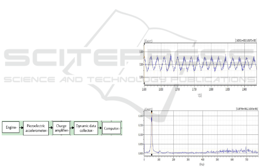
frequency domains. The engine vibration collection
system is provided by YMC PIEZOELECTRIC INC
and the schematic is shown in Figure 1.
Figure 1: The schematic of the engine vibration test
system
Vibration signals are collected in normal and no-
load running conditions and vary from seven
different speeds, as summarized in Table 1. All the
data are taken from the z-axis, which is normal to
the deck (C. Polonowski, 2007).
As shown in figure 1, the vibration signals on the
cylinder head of engine are measured by the
piezoelectric acceleration sensor (accelerometer).
But this signals are too small to show in the
measured instruments, so the measured signals are
amplified by feeding into the charge amplifier, and
the amplitude of signal are enhanced. Moreover, the
noise signal is suppressed by using dynamic data
collector. Finally, the vibration data are transmitted
to the computer by wireless communication method.
The vibration signals are measured at the condition
of the lowest 800 rpm and highest 4000 rpm for
engine speed.
3 ANALYSIS OF THE
MEASURED DATA
Vibration analysis is the most successful and cost
efficient group of condition monitoring methods.
Vibration analysis is a promising technique which is
particularly used for some time as a predictive
maintenance method and as a support for machinery
maintenance decisions (Ahmadi H, 2009). In the
proposed health monitoring system, the vibration
signals in Z direction on the cylinder head of the
engine are analysed by using the Fast Fourier
transform (FFT) in detail as follows. The plots of
vibration signal at the lowest 800 and highest 4000
speed are given in Figure 2 and 3, respectively.
(a) Time domain
(b) Frequency domain
Figure 2: The acceleration amplitude of vibration signal in
Z direction on the cylinder head of the engine at the lowest
800 rpm of speed
Research on Gasoline Engines Health Monitoring and Fault Diagnosis based on Vibration Signal Analysis
441
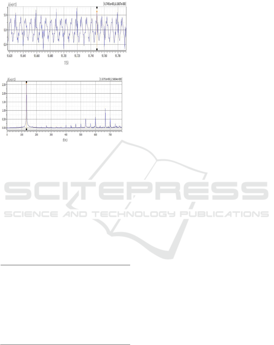
(a) Time domain
(b) Frequency domain
Figure 3: The acceleration amplitude of vibration signal in
Z direction on the cylinder head of the engine at the
highest 4000 rpm of speed.
Although the time domain wave forms of
vibration signals in Figure 2 and 3 are bewildering,
periodic gas force excitation can be observed
obviously, which is consistent with theoretical
analysis in previous. In addition, the FFT results
demonstrate the gas force’s prompted vibration is
laid on low frequency band and the value of the
frequency is apparently positively related to engine
speed, which is also confirmed in Table 1.
Table 1: The values of vibration signal in Z direction on
the cylinder head of the engine
Speed
(r/min)
Acceleration
amplitude (m/s
2
)
Acceleration
frequency (Hz)
800 -0.49 ~ 0.58 51.88
1500 -0.76 ~ 0.98 53.41
2000 -1.63 ~ 1.76 74.77
2500 -2.30 ~ 2.32 94.60
3000 -3.45 ~ 4.60 111.39
3500 -5.97 ~ 5.95 129.70
4000 -6.67 ~ 6.10 132.75
Such these characterizations provide practical
performance requirements for the design of the
engine health monitoring and fault diagnosis used in
the particular application (B. Badawi, 2006).
Adapted for engine vibration conditions under
different speeds, the designed vibration structure
should work in withstand accelerations of 7m/s
2
and
extract the electrical response in around 50 to 130Hz
frequency range.
4 CONCLUSION
In order to research on engine health monitoring and
fault diagnosis based on the characteristics of the s
from the engine, this paper proposed one method of
measuring vibration signals of engine by using
wireless acceleration sensor. The original measured
data was pre-processed using the Fast Fourier
transform (FFT) to suppress abnormal interference
of noise. The vibration signals of automotive engine
are analyzed and the results show that the method is
feasible and effective in feature extraction and
condition evaluation of engine health monitoring
and fault diagnosis.
ACKNOWLEDGEMENTS
The authors thank Chongqing Research Program of
Basic Research and Frontier Technology (Grant No.
CSTC2015jcyjA40017)
REFERENCES
Jin C., Zhao W., Liu Z., Lee J., He X. (2015) 2014
International Conference on Prognostics and Health
Management, PHM 2014, art. No. 7036371.
Chandroth, G. O., Sharkey, A. J. C., & Sharkey, N. E.
(1999). Cylinder pressures and vibration in internal
combustion engine condition monitoring. In
Proceedings of Comadem, 99.
Taglialatela, F., Lavorgna, M., Mancaruso, E., &
Vaglieco, B. M. (2013). Determination of combustion
parameters using engine crankshaft speed. Mechanical
Systems and Signal Processing, 38(2), 628–633.
doi:10.1016/j.ymssp.2012.12.009.
Gravalos, I., Loutridis, S., Moshou, D., Gialamas, T.,
Kateris, D., Tsiropoulos, Z., & Xyradakis, P. (2013).
Detection of fuel type on a spark ignition engine from
engine vibration behavior. Applied Thermal
Engineering, 54, 171–175.
doi:10.1016/j.applthermaleng.2013.02.003.
Geng, Z., Chen, J., Barry Hull, J. (2003). Analysis of
engine vibration and design of an applicable
diagnosing approach. International Journal of
Mechanical Sciences 45, 1391–1410.
ICECTT 2018 - 3rd International Conference on Electromechanical Control Technology and Transportation
442

Mollazade K, Ahmadi H, Omid M, (2009). An intelligent
model based on data mining and fuzzy logic for fault
diagnosis of external gear hydraulic pumps. Insight
2009; 51(11): 594–600.
Sakthivel NR, Sugumaran V and Babudevasenapati S.
(2010).Vibration based fault diagnosis of monoblock
centrifugal pump using decision tree. Expert Syst.
Appl.2010; 37:4040–4049.
Muralidharan V and Sugumaran V. Feature extraction
using wavelets and classification through decision tree
algorithm for fault diagnosis of mono-block
centrifugal pump. Measurement 2013; 46(1): 353–359.
C. Polonowski, V. Mathur, J. Naber, J. Blough, (2007).
Accelerometer based sensing of combustion in a high
speed HPCR diesel engine. SAE Technical Paper
2007-01-0972.
Ahmadi H and Mollazade K, (2009). Fault diagnosis of an
electro-pump in a marine ship using vibration
condition monitoring. Insight 2009; 51(8): 431–438.
B. Badawi, M. Shahin, M. Kolosy, S. Shedied et al.,
(2006). Identification of diesel engine cycle events
using measured surface vibration. SAE Technical
Paper 2006-32-0097.
Research on Gasoline Engines Health Monitoring and Fault Diagnosis based on Vibration Signal Analysis
443
