
Develo
p
ment of an Automatic Testin
g
S
y
stem for Corn
Peng Song, Han Zhang, Cheng Wang, Xiaodong Wang and Bin Luo
*
Beijing Research Center of Intelligent Equipment for Agriculture, Beijing, China
Beijing Research Center for Information Technology in Agriculture,Beijing,China
{songp, zhangha, wangc, wangxd, luob}@nercita.org.cn
Keywords: Testing system; Corn ear test; Parameters measure; Image process; Automatic control.
Abstract: Currently, the mainly used methods for corn parameters are traditional artificial method and semi-automatic
method based on machine vision technology, which restrict the efficiency of multiple date acquisition during
corn breeding. To solve this problem, an automatic testing system for corn was developed. This system is
consist of corn ear testing unit, automatic threshing unit, corn kernels testing unit, post-processing unit and
system control unit. Corn ear testing unit contains four cameras as well as a weighting sensor, which can
measure corn ear parameters such as ear weight, ear length, ear width, ear row number, grains per row, bare
tip size, et al. automatically. Corn kernels testing unit measures corn kernels parameters including kernel
color, kernel width, kernel length, kernel shape, kernel number, et al. based on computer vision technology
after kernels were spreading out by a vibrating mechanism. Post-processing unit can lift kernels to a fixed
height, packaging the kernels and print a label contains corn ear and corn kernel parameters. An industrial
control tablet combined with I/O module were chosen for the system control unit, receiving sensing
information and feedback to control the device. Results of experiment showed that the prototype can realize
the whole testing process for corn, includes ear parameters measuring, ear threshing, kernel parameters
measuring, kernel lifting, kernel packaging and label printing automatically. The average efficiency of the
prototype was up to 4 ear/minute, the average measurement accuracy for ear length and ear width is up to
98.93% and 97.71%, the average accuracy of kernel number is up to 99.11%, which can improve the
efficiency of corn breeding obviously.
1 INTRODUCTION
Corn breeding affects the quality and yield of corn.
Therefore, measurements of corn parameters
determine directly the quality evaluation and
selection of breeding materials (LIU Guanyi, 2013).
These parameters include ear weight, length, and
thickness; ear row number; row kernel grain number;
and corn kernel number, length, width, type, color,
moisture, and volume weight (Cao Jinghua, 2011).
Parameters that measure efficiency and accuracy are
key factors restricting breeding efficiency.
With the development of information technology,
machine vision and digital image processing
technologies have been used in the detection and
classification of agricultural products on a large scale
(WANG Qiao, 2017; Nayak R K, 2015;
C.Igathinathane, 2009; Cao Weishi, 2012). An
increasing number of scholars have studied the
parameter extraction method of corn ears or corn
kernels (Liu Changqing, 2014; Ma Qin, 2012; Wang
Chuanyu, 2013; Zhang Fan, 2015; Zhou Jinhui, 2015;
Wang Huihui, 2010; Lü Yongchun,2010), but only a
few have studied the design and realization of the
automatic testing system. Wang et al.(2015)
developed a maize kernel trait extraction system to
realize the measurement of total kernel number, long
and short axes, and length-width ratio through a line-
scan camera. The average measured efficiency of the
system is 12 s per ear. Xiao et al. (2015) designed an
automatic assembly line organization to measure corn
parameters and performed virtual modeling and
simulation to discuss the feasibility of the assembly
line processing for corn ear measuring. Wu et al.
(2016) designed an automatic corn ear testing system
to realize the automatic corn ear feeding, sorting,
image collection and analysis and automatic
weighing.
Existing corn testing devices and methods
measure corn ears and kernels separately rather than
simultaneously, thereby slowing down the process of
testing a large amount of breeding materials. The
high-throughput automatic corn measuring device
designed in the study realizes the rapid,
460
Song, P., Zhang, H., Wang, C., Wang, X. and Luo, B.
Development of an Automatic Testing System for Corn.
In 3rd International Conference on Electromechanical Control Technology and Transportation (ICECTT 2018), pages 460-466
ISBN: 978-989-758-312-4
Copyright © 2018 by SCITEPRESS – Science and Technology Publications, Lda. All rights reserved

comprehensive, and automatic acquisition of testing
parameters from corn ears to kernels, greatly reducing
the human cost for testing and improving breeding
efficiency. Thus, this system is of great significance
in enhancement of breeding efficiency.
2 OVERALL SCHEME DESIGN
OF THE SYSTEM
An automatic corn testing system was designed to
realize the composite measurement of the parameters
of corn ears and kernels. The modular design is
adopted to divide the automatic measuring device into
five parts according to their function, namely, corn
ear testing unit, ear threshing unit, corn kernel testing
unit, kernel post-processing unit, and system control
unit. The ear testing unit uses weighing sensor to
measure ear weight, uses multiple cameras to take
corn ear images for analysis and acquire the main
parameters of corn ear, including ear weight, ear
length, ear width, ear row number, row kernel
number, bare tip size. The ear threshing unit enables
automatic ear threshing and impurity removal after
ear testing. The kernel testing unit vibrates the
threshed kernels to avoid large-area adhesion and
accumulation. It also analyzes kernel images and
acquires kernel number, length, width, type, and
color. The kernel post-processing unit includes
pneumatic hoisting mechanism, automatic packaging
mechanism, and 2D code label printing system. This
unit prints 2D code labels first before ascending corn
kernels to a certain height and encapsulating them.
The 2D code labels contain all measured information
of the corresponding ear. The system control unit
ensures that the entire system is running orderly,
stably, and automatically. The Principle of the
automatic testing system for corn is shown in Fig. 1.
Fig.1 Principle of automatic testing system for corn
3 KEY UNIT DESIGN
The automatic testing system is mainly composed of
corn ear testing unit, automatic threshing unit, corn
kernel testing unit, post-processing unit and system
control unit. A thresher for single ear from Canada is
chosen for the core of automatic threshing unit,
threshing efficiency can up to 3~5 s/ear, with low
breakage. For post-processing unit, a vacuum suction
machine was used to lifting kernels, which can ensure
the lifting process without mixture between
neighboring corn. Thus, the key elements of the
system include core ear testing unit, corn kernel
testing unit and system control unit.
3.1 Corn Ear Testing Unit
Corn ear parameters include ear weight, ear length,
ear width, ear row number, row kernel number, bare
tip size, average kernel thickness, and ear color. To
ensure that the ear testing unit can adapt to the
detection requirements of various forms of corn ears
and provide consideration to the precision and speed
of ear testing in the automatic testing process, the ear
testing unit structure is designed, as shown in Fig. 2.
Fig.2 Structure of corn ear testing unit
Development of an Automatic Testing System for Corn
461
1.Weighing sensor 2.Ear loading sensor 3.Ear unloading
motor 4.Cameras for ear images 5.Ear unloading sensor 6.
Load bearing steel wire 7. Corn ear carrying device
8.bearing bracket 9.Sample under test
Ear testing unit mainly includes weighing sensor,
cameras, and ear bearing mechanism, the ear bearing
mechanism consists of a bearing bracket and an ear
bearing device. The whole ear bearing mechanism is
placed above the weighing senor with a range of 0~10
kg and a precision of 0.1 g. The ear bearing device
adopts two Tungsten wires with high hardness and a
diameter of 1.5 mm. Those two wires are installed in
parallel with adjustable space. During work, the
sample ear is placed above two wires. Four high-
resolution color cameras are evenly distributed
around the ear with an interval of 90° to acquire corn
ear images in four directions. In this study, ear images
are taken using a high-resolution color CMOS
industrial digital camera and the lens with a focal
length of 5 mm. In addition, four 12 V bar LED white
light sources are distributed in the middle of the
adjacent cameras to guarantee uniform illumination.
Ear loading sensor detects ear feeding, which triggers
four cameras to acquire ear images and record ear
weights simultaneously. Then, ear unloading motor
drives the ear carrying device to revolve round the
axis. The ears slide down to the threshing unit under
the effect of gravity, which resets both the unloading
motor and the bearing device, waiting for the feeding
of the next ear. The ear unloading sensor is installed
at the discharge outlet to detect whether the corn ear
is successfully discharged to the kernel threshing unit.
3.2 Kernel Testing Unit
When the testing system works, corn kernels after
being threshed and cleaned are randomly scattered in
the kernel testing unit under the effect of gravity. At
this time, the industrial camera is used to acquire
kernel images and then obtain the kernel parameters,
including kernel number, kernel shape, length, width,
and color. Corn kernels, which are scattered in the
kernel testing unit after being threshed and cleaned,
are easily adhered and accumulated. Thus,
guaranteeing the accuracy of the kernel parameters is
difficult if the images to process are directly acquired.
To solve the problem, the kernel testing unit consists
of three parts: (1) image acquisition device for
collecting kernel images; (2) automatic spreading
mechanism for reducing kernel adhesion and
accumulation and obtaining high-quality kernel
images; and (3) kernel discharging mechanism for
ensuring the smooth implementation of high-
throughput assembly line operation and allowing the
discharge of kernels whose test parameters have been
measured into the next link. The structure of the
kernel testing unit is shown in Fig. 3.
Fig.3 Structure of corn kernels testing unit
1. Vibration platform 2. Kernel layer board 3. Threshing
unload sensor 4. Strip source 5. Camera for kernels image
The camera of the kernel image acquisition device
adopts a high-resolution color CMOS industrial
digital camera. The CMOS size of the camera is 1/2.5
inch with an imaging resolution of 2592 × 1944
pixels. After the test, the corn kernel distribution area
is designed to 50 cm × 40 cm to improve the pixel
utilization rate of the camera and meet the testing
demands of single-corn ear kernels of different
specifications.
The automatic spreading mechanism vibrates the
plate containing corn kernels under the drive of the
vibrating platform before the acquisition of corn
kernel images to avoid corn kernel accumulation.
After spreading, it triggers the camera to acquire
kernel images. The kernel discharging mechanism
uses the linear motor to drive the kernel plate to form
a certain angle and make the kernels slide down under
the effect of gravity.
3.3 System Control Unit
The Kunluntongtai TPC7062K industrial control
tablet and the Modbus input–output module comprise
the control system. The Modbus module uses the
RS485/RS232-based Modbus RTU standard
communication protocol with 16 photoelectric
isolating switch input channels and 16 photoelectric
isolating relay output channels.
After corn ear feeding, the ear loading and
unloading sensors are installed at the ear processing
unit, the kernel threshing detection senor at the outlet
of the threshing unit, and the kernel discharging
sensor at the outlet of the kernel testing unit. This
procedure realizes the automation of ear image
acquisition and analysis, discharging, kernel
threshing and spreading, kernel image acquisition and
analysis, as well as lifting, packaging and label
printing. The output signals of the sensors are all
switch quantities, which are taken as the input signals
to control the testing system according to the
ICECTT 2018 - 3rd International Conference on Electromechanical Control Technology and Transportation
462

designed logic and time sequence. The overall design
of the control system is shown in Fig. 4.
Fig.4 Overall design of control system
The system uses four input signal terminals and
12 output signal terminals. In addition, it is comprised
of three sets of mechanical switches, namely, system
power-on, control system start/stop, and power
system emergency shutdown. The input-output signal
terminal configuration of the control module is shown
in Table 1.
Table 1 I/O ports configuration of control module
Name
Port
channel
Signal connected
Input port
10001 Ear loading senso
r
10002 Ear unloading senso
r
10003 Threshing output senso
r
10004 Kernel unloading senso
r
Output
port
00001 Motor for ear unloading(extending)
00002 Motor for ear unloading(restoration)
00003 Signal for ear image acquisition
00004 Start stop signal of threshing
00005 Signal of kernel vibration platfor
m
00006
Motor for kernel
unloading(extending)
00007
Motor for kernel unloading
(restoration)
00008 Signal for kernel image acquisition
00009 Start stop signal of lifting device
00010 Kernel unloading signal after lifting
00011 Packaging signal
00012 Barcode printing signal
When the power is turned on, the control system
starts and the device completes initialization to wait
for ear feeding. Ear loading sensor detects the ear
information and then judges the kernel discharging
state of the last ear. If the last ear’s kernel is
discharging or already discharged successfully, the
ear weight is read from the weighing sensor. At the
same time, four cameras are triggered to collect the
ear images from four angles. If the last ear’s kernel
has not discharged kernels yet, the mechanism waits.
The kernel process of the last ear must be completed
when the current ear threshes kernels to avoid the
mixture of kernels on adjacent ears during measuring.
The acquired ear images are processed to extract ear
parameters. On the contrary, the ears are discharged
to reset the weighing sensor. When the ear
discharging sensor detects the entry of ears into the
thresher, the thresher starts to thresh corn kernels. At
this time, the threshed kernels are scattered in the
kernel testing unit. When detecting the scattering of
kernels at the outlet of the thresher, the vibration
spreading mechanism vibrates until the threshing is
completed to avoid large-area kernel adhesion and
accumulation. The camera of the kernel testing unit is
triggered to collect kernel images, which are then
processed. At the same time, the kernels are
discharged and the fan of the pneumatic lifting device
starts to lift the kernels to the specified height and
package them. After processing the kernel images and
obtaining the kernel test information, the ear test 2D
code is automatically printed and the test parameters
of the corresponding ears and kernels are written into
the 2D code. The system control process is shown in
the figure below.
Start
System Initialization
Ear load succeed?
Ear weighting & ear
images acquisition
Ear loading, reset
weight sensor
Ear unloading
succeed?
Ear threshing,vibrate
to spread kernels
Threshing over?
Stop vibrating
N
Y
N
Y
Y
Ear testing
Kernel image
acquisition
Kernel
discharging
Kernel
testing
Kernel discharged?
Kernel lifting
End
The last ear unloaded?
Y
Y
N
Packaging, label
printing
Fig.5 The flow chart of system control
4 EXPERIMENT AND ANALYSIS
The automatic testing system for corn was built
according to the design shown in Fig. 6. Then, the
corn testing experiment was carried out. Test samples
were composed of the corns harvested in Hainan
breeding base of Liaoning Dongya Seed Industry Co.,
Ltd.
Development of an Automatic Testing System for Corn
463

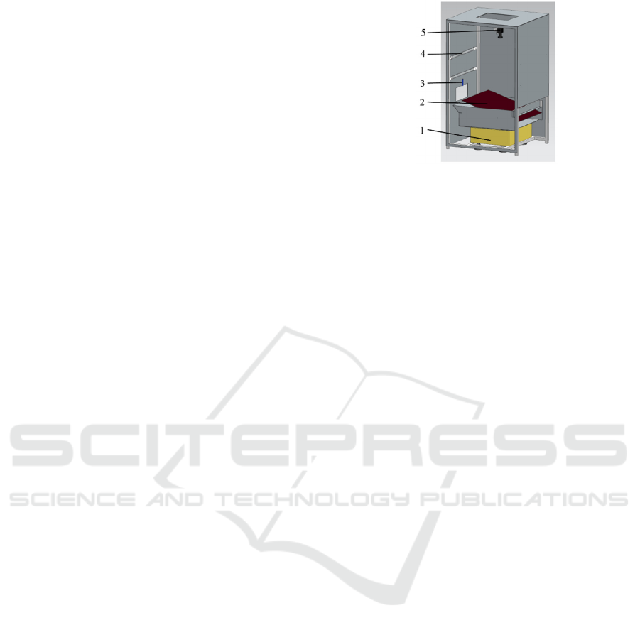
Fig.6 The prototype
4.1 System Operation Test
During the test, the total time consumed for a single
corn ear from artificial feeding to kernel packaging
was recorded. Twenty ears were randomly selected.
Statistical results showed that the average time was
27.2 s per ear.
On this basis, 50, 100, and 150 corn ears were
randomly selected for the experiments. Three runs of
experiments were conducted to verify the stability
and operation speed of the system. In each group of
test, the ears were fed continuously. In other words,
when the last corn ear was discharged automatically
and the ear bearing mechanism was reset, the next one
was fed rapidly. The total time from feeding the first
ear to packaging the last one in each group of samples
was recorded.
Then, the average time consumed for single corn
ear test during the continuous operation of the system
was
()/(1)tTt N=−Δ −
, where T is the total time
consumed for the test of each group of samples;
tΔ
is the whole process time consumed by a single ear,
having a constant of 27.2;
and N is the total number of samples.
Table 2 Processing efficiency at continuous mode
No.
Sample
number
Total time
consuming/s
Processing
effiency/(Ear·min
-1
)
1 50 759.5 4
2 100 1490.4 4
3 150 2231.3 4
The results show that the average efficiency of the
prototype was up to 4 ear/minute, which can improve
the efficiency of corn breeding obviously.
4.2 Ear Testing Experiment
Among ear testing parameters, except the ear weight
that was acquired by the weighing sensor, other
parameters such as ear length, ear diameter, bare tip
size, ear row number, row kernel number, kernel
thickness, and ear color were obtained by four
cameras from four angles. The ears were placed
between two high-strength steel wires. Thus, four
original ear images were obtained by four cameras of
the system, which are shown below.
(a) (b) (c) (d)
(e) (f) (g) (h)
(a)Original image of Cam. 1 (b)Original image of Cam. 2
(c)Original image of Cam. 3 (d)Original image of Cam. 4
(e)Background removal for Fig.8(a) (f)bare tip extract for
Fig.7(a) (g)kernel extract for Fig.7(a) (h)kernel track for
Fig.7(a)
Fig.7 Images of corn ear and the processing results
Table 3 Results for corn ear testing
Sample
No.
Ear length Ear width
Ear rows
Measu-
red
manual-
ly/mm
Measu-
red by
system/
mm
Accu-
racy/
%
Measu-
red
manual
ly/mm
Measu-
red by
system/
mm
Accu-
racy/
%
Measu-
red
manually
/mm
Measu-
red by
system/
mm
1
131.68 133.76
98.44
40.36 40.48
99.70
14 14
2 121.02 122.97 98.41 38.52 39.49 97.54 14 12
3 95.74 96.85 98.85 35.42 36.88 96.04 16 16
4 108.32 109.26 99.14 41.86 43.07 97.19 16 16
5 117.36 119.39 98.30 45.26 46.52 97.29 16 16
6 145.62 147.08 99.01 40.78 41.52 98.22 16 16
7 168.34 169.97 99.04 49.70 51.34 96.81 18 18
8 108.94 109.56 99.43 42.68 43.53 98.05 14 14
9 73.48 73.92 99.40 31.26 31.48 99.30 12 12
10 97.88 98.24 99.63 41.28 42.36 97.45 14 14
Averag
e
1168.38 1181 98.93 407.12 416.67 97.71 150 148
4.3 Kernel Testing Experiment
After background removal and separation of adhered
kernels, the original images obtained in the corn
kernel testing unit were analyzed. Single kernels were
ICECTT 2018 - 3rd International Conference on Electromechanical Control Technology and Transportation
464

studied to measure kernel number, kernel type, kernel
length, kernel width, and other testing parameters.
The original kernel images obtained by the automatic
testing device and the kernel separation results are
shown in Fig. 8.
(a)Original kernel image (b) Segment result
Fig. 8 Image of corn kernels and the processing result
Table 4 Results of maize kernel number measuring
No.
Measured
manually
Measured by
system
Accuracy/%
1 351 344
98.01
2 424 419
98.82
3 505 499
98.81
4 318 316
99.37
5 492 487
98.98
6 276 276
100.00
7 532 530
99.62
8 582 577
99.14
9 429 428
99.77
10 367 362
98.64
Average 4276 4238 99.11
5 CONCLUSIONS
An automatic testing system for corn was designed in
this study to realize corn ear testing, automatic
threshing, kernel testing, automatic packaging, 2D
code generation and printing. On this basis, a
prototype machine was developed to test the stability
and efficiency of the system. Experimental results
showed that the automatic testing system could
automatically acquire various parameters involved in
the corn ear and kernel testing process. The average
efficiency of the prototype was up to 4 ear/minute.
The average measurement accuracy for ear length and
ear width is up to 98.93% and 97.71%. The average
accuracy of kernel number is up to 99.11%.These
results indicate that the system can greatly improve
the corn breeding efficiency.
ACKNOWLEDGEMENTS
This work was financial supported by the National
Key Research and Development Project
(2017YFD0701205)
REFERENCES
LIU Guanyi,YANG Xiaohong,Bai Ming,et al. Detecting
techniques of maize ear characters based on line scan
image[J]. Transactions of the Chinese Society for
Agricultural Machinery, 2013, 44(11): 276-280.(in
Chinese with English abstract)
Cao Jinghua,Ran Yanzhong, Guo Jincheng. The design and
realization of corn test system[J]. Journal of Changchun
Normal University: Natural Science, 2011, 30(4): 38-
41.
WANG Qiao,CHEN Bingqi,ZHU Deli,et al. Machine
Vision-based Selection Machine of Corn Seed Used for
Directional Seeding[J]. Transactions of the Chinese
Society for Agricultural Machinery. 2017,48(2): 27-37.
(in Chinese with English abstract)
Nayak R K,Mishra D,Rath A K. Anaive SVM-KNN based
stock market trend reversal analysis for Indian
benchmark indices[J]. Applied Soft
Computing,2015,35: 670-680.
C.Igathinathane, L. O. Pordesimo, W. D. Batchelor. Major
orthogonal dimensions measurement of food grains by
machine vision using ImageJ. Food Research
International, 2009, 42:76~84.
Cao Weishi, Zhang Chunqing, Wang Jinxing, et al. Purity
identification of maize seed based on discrete wavelet
transform and BP neural network. Transactions of the
Chinese Society of Agricultural Engineering, 2012,
28(2):253-258.
Liu Changqing,Chen Bingqi. Method of image detection
for ear of corn based on computer vision[J].
Transactions of the Chinese Society of Agricultural
Engineering (Transactions of the CSAE), 2014, 30(6):
131-138. (in Chinese with English abstract)
Ma Qin, Jiang jingtao, Zhu Dehai et al. Rapid measurement
for 3D geometric features of maize ear based on image
processing[J]. Transactions of the Chinese Society of
Agricultural Engineering. 2012, Vol.28 Supp.2, 208-
212.
Wang Chuanyu,Guo Xinyu,Wu Sheng,et al. Investigate
maize ear traits using machine vision with panoramic
photograyphy[J]. Transactions of the
CSAE,2013,29(24):155-162. (in Chinese with English
abstract)
Zhang Fan, Li Shaoming, Liu Zhe, et al. Screening Method
of Abnormal Corn Ears Based on Machine Vision[J].
Transactions of the Chinese Society for Agricultural
Machinery, 2015,46(Supp.):45-49. (in Chinese with
English abstract)
Zhou Jinhui,Ma Qin,Zhu Dehai,et al. Measurement
method for yield component traits of maize based on
Development of an Automatic Testing System for Corn
465

machine vision [J] . Transactions of the Chinese
Society for Agricultural Machinery,2015,46(3) :221-
227. (in Chinese with English abstract)
Wang Huihui,Sun Yonghai,Zhang Tingting,et
al.Appearance quality grading for fresh corn ear using
computer vision[J].Transactions of the Chinese Society
for Agricultural Machinery,2010,41(8):156-159, 165.
Lü Yongchun, Ma Qin, Li Shaoming, et al. Image features
measurement of maize ear based on background plate
scale[J].Transactions of the Chinese Society of
Agricultural Engineering, 2010, 26(14): 43-47. (in
Chinese with English abstract)
WANG Ke,LIANG Xiuying,ZONG Li, et al. Design
and Realization of a High-throughput Maize Kernel
Trait Extraction System[J]. Journal of Agricultural
Science and Technology, 2015,17(2): 94-99. (in
Chinese with English abstract)
XIAO Boxiang,WANG Chuanyu,GUO Xinyu,et al.
Automatic pipelining mechanism design for maize ear
analysis[J]. Journal of System Simulation, 2015,
27(4):913-919. (in Chinese with English abstract)
Wu Gang, Chen Xiaolin, Xie Jiayu, et al. Design and
Experiment of Automatic Variety Test System for Corn
Ear[J]. Transactions of the Chinese Society for
Agricultural Machinery, 2016, 47(Supp.): 433-441. (in
Chinese with English abstract)
ICECTT 2018 - 3rd International Conference on Electromechanical Control Technology and Transportation
466
