
Load Monitoring for Orthoses with Energy Harvesting Powered
Sensor
Juan-Mario Gruber and Andreas Stahel
Institute of Embedded Systems Zurich University of Applied Sciences, Winterthur, Switzerland
Keywords: Energy Harvesting, Sensors, Force Measurement.
Abstract: A new self-powered sensor with wireless connectivity is presented. The system is powered by piezoelectric
energy harvesting from human motion. It can be implemented for example into orthoses, medical walking
aids, shoes or prostheses. Force sensors measure the weight bearing on a lower limb. The collected data is
processed and transmitted to a smartphone or computer using Bluetooth Low Energy (BLE). On the
receiving device, the data is analysed and visualized and can provide information for patients and physicians
to support healing processes. Initial tests show that the harvested energy is sufficient for a stable operation
of the embedded system.
1 INTRODUCTION
Patients with injuries on lower limbs need to reduce
the weight bearing on the leg or foot during
recovery. Over-straining can cause a delay of the
healing process or even new injuries. However, it
can be difficult for a patient, to estimate the applied
weight. An appropriate tool can help monitoring
with continuous measurements using force sensors.
It can trigger a warning, if overstraining is
imminent. Built into a cast or an orthosis, a small
and light device does not interfere with the patient in
daily life. In general, the possibility to monitor a
patient constantly over a period of time with small
effort for both patients and physicians offers new
possibilities in diagnostics or in supporting
treatment.
Usually wearable devices are powered by a
rechargeable battery (
Merrett et al., 2010). This
increases weight and size and can make the use of
the product as well as its designing more
complicated, for example with regard to
waterproofness and reliability. In addition, the
materials used for the production of batteries, as well
as their disposal at the end of the product lifetime
poses a potential risk for the environment.
Instead of using a battery, the energy needed to
operate a wearable device can be harvested from the
environment. Typical sources are light, body
temperature or mechanical forces. In recent years,
there was rapid development towards more energy
efficient devices. Therefore, there are more and
more applications, where energy harvesting is a
possible solution.
By using energy harvesting as a source of
energy, the threshold for application is lowered
compared to using a battery or accumulator. The
user does not need to perform maintenance tasks like
changing or charging a battery before use, but can
instead put the device into operation immediately.
This makes such a device convenient also for less
technically oriented users, for example elderly
people. In addition, it increases safety and reliability
of the device since it is not dependent of a limited
energy supply.
2 PIEZOELECTRIC ENERGY
HARVESTING FROM
MECHANICAL FORCES
The piezoelectric effect is used in sensor
technologies in various applications. When
piezoelectric materials are deformed, they produce a
voltage proportional to the applied force. The
preferred way to use the piezoelectric effect in
energy harvesting is to exploit vibrations with a
piezoelectric oscillator. When operated at resonance
frequency, it can produce a decent amount of power.
134
Gruber, J. and Stahel, A.
Load Monitoring for Orthoses with Energy Harvesting Powered Sensor.
DOI: 10.5220/0007253901340139
In Proceedings of the 12th International Joint Conference on Biomedical Engineering Systems and Technologies (BIOSTEC 2019), pages 134-139
ISBN: 978-989-758-353-7
Copyright
c
2019 by SCITEPRESS – Science and Technology Publications, Lda. All rights reserved

However to keep a piezoelectric oscillator at
resonance frequency, a very steady movement or
vibration is required, which in reality is often not the
case. The power output decreases drastically, if the
oscillator is not in resonance.
Figure 1: Impact force on the base of an orthosis, used to
deform the piezoelectric element (Source: Colourbox,
modified).
In this application, energy is harvested from
human motion like walking. Because of the low
speed of the movement and its inconsistency,
resonances cannot be exploited. Instead the events of
force impact have to be treated as single events,
from which as much energy as possible has to be
harvested.
3 OVERALL CONCEPT
The presented prototypical system showed in Figure
2 consists of an energy harvester, a microcontroller
with a BLE transmitter, a force sensor and an
Android application (Stahel and Hermann, 2017).
In the energy harvester, a piezoelectric element
transforms mechanical forces into electric energy.
The energy is stored in a capacitor, which is
monitored by an energy management unit. A step
down converter provides the voltage level for the
microcontroller.
At each program cycle, triggered by the piezo
harvester, the microcontroller evaluates the force-
sensing resistor. This data is then sent via BLE in
advertising mode and is received and visualized by
an Android application.
Figure 2: Overall concept of the presented solution.
3.1 Energy Harvesting
A piezo buzzer (Figure 3) is usually used as an
actuator to produce a sound signal by applying an
AC Voltage in a particular frequency. It is used in
cheap speakers to produce warning signals or other
low quality sounds. Thanks to their simple structure
and mass production, they are very affordable.
Figure 3: Standard piezo buzzer used for the application.
In this application, a piezo buzzer is
implemented as a generator. By deforming the
buzzer a voltage between the piezo ceramic layer
and the brass base is produced that can be harvested
by a suitable circuit.
Ideally, the piezo buzzer it is placed at a position,
where the first force impact occurs. For an orthosis,
the optimal position would on the bottom side
(Figure 1), for crutches, the buzzer can be positioned
at the tip or inside the joint in the shaft.
At every step, the device uses the first impact on
the piezo buzzer as a trigger point to wake up the
microcontroller and start the measurement routine.
For that purpose, a high-pass filter is connected to
the piezo buzzer to register the rising voltage and to
provide an input signal to the comparator of the
microcontroller.
The energy yield of the piezo buzzers was
evaluated in laboratory tests. Depending on the
preload of the storage capacitor, an energy yield of
up to 3 mJ from a single stroke could be achieved
Load Monitoring for Orthoses with Energy Harvesting Powered Sensor
135
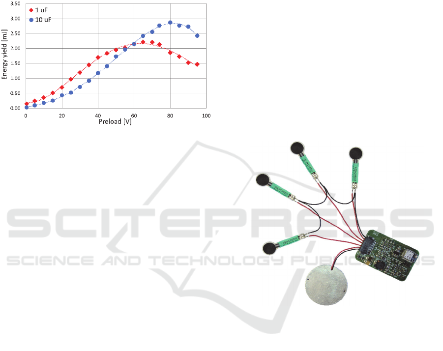
(Figure 4). Two or more piezo buzzers can also be
stacked to increase the energy yield.
For these measurements the piezo buzzers where
connected to a full bridge rectifier consisting of
BAT54 diodes and to a capacitor. The voltage level
of the capacitor after each pulse was evaluated and
the resulting energy calculated.
Figure 4: Energy yield of piezo buzzers at different
preloads and with two different storage capacitor sizes.
The main element of the harvester circuit is an
LTC3588 chip from Linear Technology. It is a
specialized chip for energy harvesting from
piezoelectric sources and consists of a rectifier and
an efficient buck converter to convert the input
voltage of the piezo buzzer into a stable output of
1.8 Volt. The input voltage of the LTC3588 is
limited to 20 Volt. Before converting, the energy is
buffered to bridge idleness.
3.2 Microcontroller and Sensors
Based on (Gugg et al., 2016) an NRF52832
microcontroller by Nordic Semiconductors was used
as a basis for the embedded system. It contains an
ARM Cortex M4 32-bit processor as well as a
2.4 GHz transceiver for BLE. To measure the
weight, force sensing resistors where implemented.
The microcontroller can evaluate them using its 12-
bit analog-to-digital converter (ADC).
With an additional ADC measurement, the
voltage level of the storage capacitor is monitored.
Depending on the available energy in the storage,
the collected data is sent via BLE. In continuous
operation, it is possible to evaluate the sensors and
send the data at every step, thanks to very low power
consumption.
The ADC measurement, including initialization,
data acquisition and data transfer with Direct
Memory Access (DMA) consumes only 1.1 μJ.
Sending the data in advertising mode on three
channels uses around 20 μJ at a transmission power
of 0 dBm. The transmission power was chosen to
ensure a stable communication, but can be reduced
to save energy. Standby phases of the
microcontroller in between two steps consume
8.1 μJ per second.
4 PROTOTYPE
A prototypic implementation of the autarkic sensor
was implemented. It consists of a harvester system, a
microcontroller with BLE transmitter and force
sensing resistors (Figure 5).
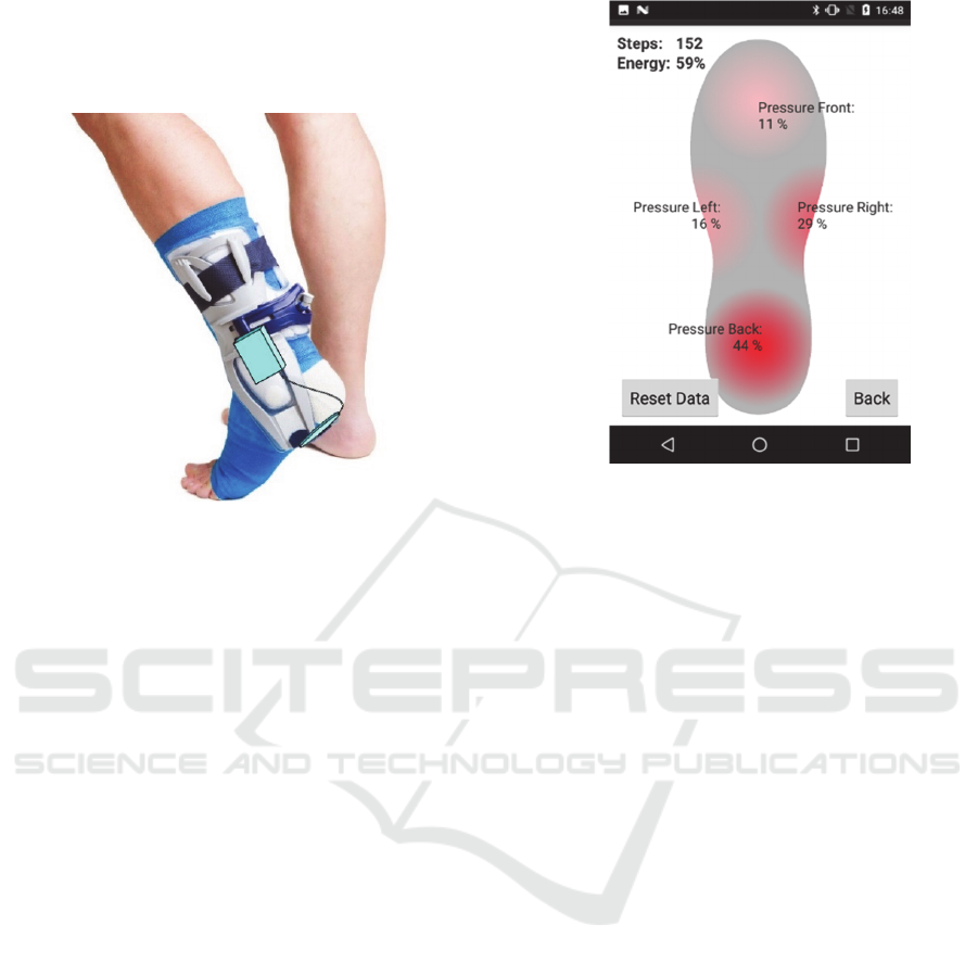
The system was fitted into an insole. Apart from
monitoring weight load, this device demonstrates a
different potential application. By spreading the
force sensors on the sole, the device measures the
weight distribution. It could be used for orthopedic
gait analysis.
Figure 5: Overview over prototypic system. The piezo
buzzer is placed inside an aluminum housing.
The system contains no moving parts. The most
stress is on the piezo buzzer that has to be deformed
at every cycle. This could potentially damage the
piezo-ceramic layer on top in the long term. To
prevent this, the piezo buzzer was placed inside an
aluminum housing. This allows limiting the maximal
bending to 2 mm. The power output is only
marginally affected this limitation. It is also largely
independent of the weight of the user. The piezo
buzzer can be bent with little force.
The complete system with piezo buzzer, four
force sensors and the microcontroller circuit board
can be fitted on an orthosis (Figure 6).
Miniaturization can presumably be achieved by a
factor of two or more, so that the autarkic sensor
system can also be used in a more limited space like
BIODEVICES 2019 - 12th International Conference on Biomedical Electronics and Devices
136
crutches. Introducing additional sensors or circuitry
is possible, provided the energy budget is taken into
account. At a weight of only a few grams, the device
does not bother the wearer during use.
Figure 6: View of a possible mounting of the system on an
orthosis. The piezo buzzer and sensors are placed at the
bottom, the microcontroller is mounted on the side
(Source: Colourbox, modified).
The bill of material of the prototype device,
excluding force sensors, adds up to around 40 USD.
This includes the piezo buzzer that is very affordable
at a price of only 2.80 USD. The used force sensing
resistors cost an additional 20 USD per piece.
4.1 Android Application
The sensor system sends the data of the force
sensors, the measured voltage value of the storage
capacitor and a step counter value using advertising
mode. Each packet has a length of ten bytes and is
sent three times successively. For processing and
visualization, the data can be received by an
application that runs on any Android smartphone
capable of BLE.
The Android application scans for advertising
data, recognizes the packets by their ID and extracts
the sensor data.
The application uses calibration data of the force
sensors to scale the measured values and display
their relative distribution by using text and color.
The step counter data and the current energy storage
level is also displayed (Figure 7).
To display the current weight load in total the
application can be modified. With the weight of the
person and the calibration data of the force sensors,
the total load can be calculated and displayed both
graphically and textually. The step counter would be
Figure 7: Sample view of the application. The color and
percentage value indicate the current weight distribution
on the foot.
of marginal interest in such an application and could
be omitted.
Signaling imminent overstraining could also be
done in a different way than via an Android
application. An acoustic or a tactile indication could
be implemented, depending on the use case and
energy budget. This way, the inhibition threshold
can be lowered further to make the device accessible
to less technically oriented users who might have
difficulties to use a smartphone.
4.2 Performance
When the system is fully started up, it can be
sustained with an energy pulse frequency from the
piezo buzzer of less than 1 Hz, which corresponds
with a normal walking speed of an injured person.
Data acquisition, processing and transmitting and the
standby of the microcontroller consume around
30 μJ at each cycle. The harvesting system provides
around 90 μJ of energy at each pulse on average
(Figure 8, right side).
In conclusion, the system can store up to 60 μJ
on average at each pulse and can thus sustain
operation in standby for a certain time, while no
energy can be produced. The storage capacitors will
then eventually discharge due to leakage.
Starting up the embedded system consumes
around 100 μJ and can be done after about five
pulses from the piezo buzzer, as laboratory tests
have shown. The amount of energy produced is
Load Monitoring for Orthoses with Energy Harvesting Powered Sensor
137
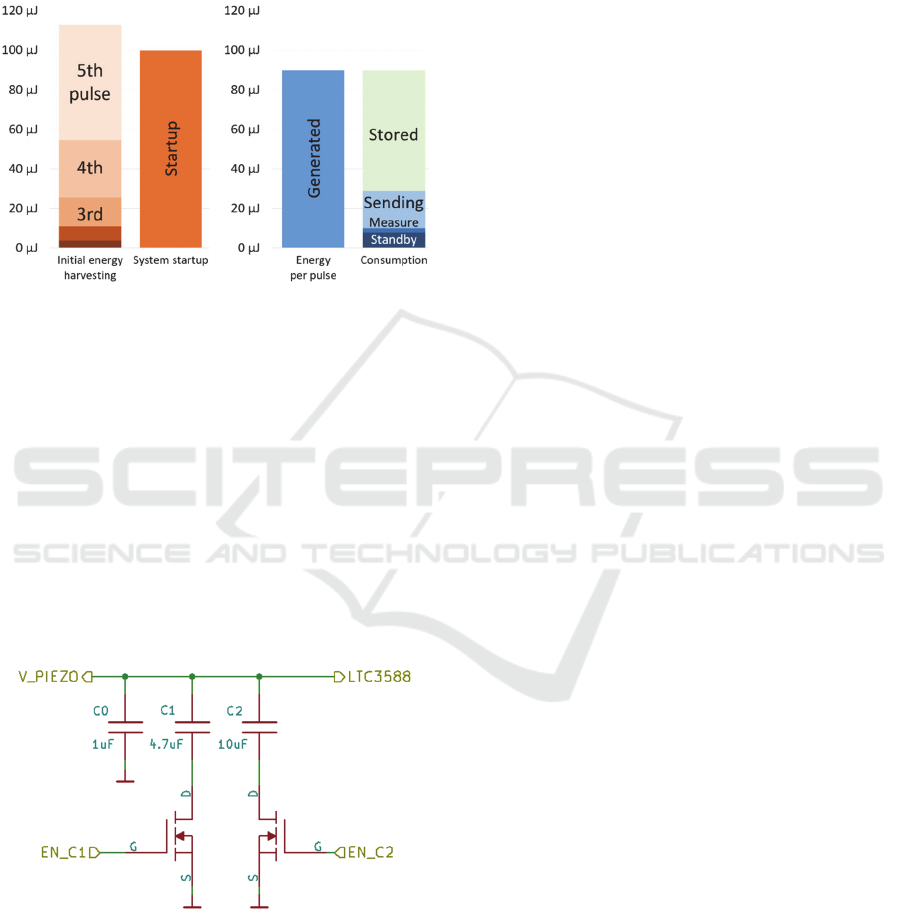
significantly smaller during the first few pulses with
empty storage capacitors and improves with
increasing charge of the capacitors as shown in
Figure 4. Therefore, the initial startup of the system
poses a challenge. This is indicated in Figure 8 on
the left side.
Figure 8: Comparison between generated and consumed
energy. Left: Startup process (approximated); right:
continuous operation.
To improve the start-up procedure, an array of
storage capacitors is introduced (Figure 9). It
consists of three different capacitors in parallel that
can be enabled according to the current operating
state. At start-up, a small capacitor is used to provide
the buck converter with a high voltage as quickly as
possible. For continuous operation, additional
capacitors are activated to provide enough storage.
Due to the charge equalization that takes place when
a new capacitor is activated, the larger capacitors do
not need to be charged from an empty state, which
improves efficiency significantly.
Figure 9: Schematics of storage capacitor array.
5 APPLICATIONS
The presented system provides a wide array of
possible applications. Examples are medical walking
aids (
Merrett et al., 2009)
, supports, rails or
prostheses. It can be implemented to measure the
applied weight bearing on an injured lower limb
after a fracture or a cruciate ligament tear for
example. This way the system can help to improve
the healing process and prevent damages from
overstraining.
By recording and live reporting data about the
weight distribution on the foot, the autarkic sensor
system can be used as a tool in orthopedic gait
analysis (
Hadi
et al. 2012). For this, several force
sensing resistors can be placed on different spots on
an insole. Elderly people in need of care can be
monitored to register falls and signal for help. With
no needed maintenance, the device is very user-
friendly.
The implemented sensor types are not limited to
sensing force. Measuring temperature over a longer
period of time is a further possible scenario for
medical applications.
This autarkic sensor system can also be adapted
to other fields of application. As a safety monitoring
system, for example for firefighters, it can trigger an
alarm if no data is transmitted, meaning that the
person wearing the system is not moving. Such a
device can be used to simplify access control. Doors
can be unlocked if a person with right of access
approaches or locked otherwise. For this application,
an embedded system can be built into specialized
safety shoes or into an insole that can be inserted in
any shoe.
Another use case is a wearable fitness gadget that
counts steps or tracks position. Energy harvesting
simplifies the usage of such a gadget significantly,
since it is independent from any limited battery
lifetime.
Apart from exploiting a walking movement, the
developed system is also suitable for other
applications in which a mechanical motion is
present. Harvesting energy can also be done from an
industrial machine with moving parts, while the
autarkic sensor monitors a process or machine in the
production line.
6 CONCLUSIONS
The target of this project was to implement a sensor
to monitor and support a healing process by
measuring the applied weight on an injured lower
limb.
Several other works in this field have been done
previously. Comparable systems use batteries
(
Merrett et al., 2009)
that need to be replaced or
BIODEVICES 2019 - 12th International Conference on Biomedical Electronics and Devices
138

charged. Introducing energy harvesting as a power
supply increases the security of the system and
makes it more user-friendly. Electrical energy is
generated directly from the human motion and is
available as needed.
The presented system is preferably implemented
into foot or leg orthoses, prostheses, shoes or into
crutches since the energy harvesting system relies on
the vertical force from the weight of the wearer. The
piezoelectric element produces a voltage when being
deformed. With some adjustments, it is also possible
to apply the sensor system on other body parts, such
as the arms, provided a mechanical movement is
present that can be used to bend the piezo buzzer.
A two-part system, where energy is harvested
from the walking motion and a sensor is used to
monitor another part of the body can also be taken
into consideration. However, user-friendliness
would be reduced by a device more complicated to
apply.
The prototypic system has potential to be
optimized in future work. This includes optimizing
the harvester circuit in terms of efficiency and input
voltage range. The used LTC3588 buck converter is
limited to 20 Volts. Tests showed a significantly
higher efficiency at higher voltages of up to
80 Volts. This potential should be exploited.
The possibility to stack the piezo elements is also
worth analyzing. Two or more piezo buzzers can be
used simultaneously to increase the power output at
the cost of a larger device. Depending on the
application and the required energy, it could be a
viable solution.
An expansion of functionality is planned,
particularly with respect to the used sensor types and
construction form, to implement other applications.
REFERENCES
Merrett, G., Ettabib, M., Peters, C., Hallett, G., White N.,
2010. Augmenting forearm crutches with wireless
sensors for lower limb rehabilitation. In Measurement
Science and Technology, 21 (12), 1-10, 2010
Stahel A., Hermann A., 2017, Energieautarker,
intelligenter Schuh, Zurich University of Applied
Sciences. Switzerland.
Gugg, M., Brütsch, M., Brülisauer, C., Meli, M., 2016
Comparing the energy requirements of current
Bluetooth Smart solutions, Zurich University of
Applied Sciences. Winterthur.
Merrett, G., Peters, C., Hallet, G., White, M., 2009, An
instrumented crutch for monitoring patients’ weight
distribution during orthopaedic rehabilitation,
University of Southampton. Southampton.
Hadi, A. Razak, A., Zayegh, A., Begg, R., Wahab, Y.,
2012. Foot Plantar Pressure Measurement System: A
Review. Victoria University, School of Engineering
and Science. Melbourne.
Load Monitoring for Orthoses with Energy Harvesting Powered Sensor
139
