
A Metamodel and Model-based Design Rule Checking DSL for
Verification and Validation of Electronic Circuit Designs
Adrian Rumpold and Bernhard Bauer
Institute of Computer Science, University of Augsburg, Germany
Keywords:
Domain-specific Modeling, Model-based Analysis, Model-based Testing and Validation, Systems
Engineering, Electronic Design Automation, Design Rule Checking.
Abstract:
Development of embedded systems depends on both software and hardware design activities. Quality
management of development artifacts is of crucial importance for the overall function and safety of the final
product. This paper introduces a metamodel and model-based approach and accompanying domain-specific
language for validation of electronic circuit designs. The solution does not depend on any particular
electronic design automation (EDA) software, instead we propose a workflow that is integrated into a modular,
general-purpose model analysis framework. The paper illustrates both the underlying concepts as well as
possible application scenarios for the developed validation domain-specific language, MBDRC (Model-Based
Design Rule Checking). It also discusses fields for further research and transfer of the initial results.
1 INTRODUCTION
Embedded hardware and computing have become
pervasive aspects of modern technology, which
we encounter under a variety of different names:
cyber-physical systems, embedded systems, smart
devices, and not least the Internet of Things.
While different in their concrete use cases and
implementation, they all share a common underlying
concept, the close connection between software and
hardware aspects. Their design and development
activities differ, but ultimately both need to be
actively quality managed in order to attain a sufficient
level of quality. This quality may be expressed in
terms of freedom from errors, but may also refer to
aspects such as reliability, dependability, and safety,
depending on the application domain.
Hardware design, and the design of electronic
circuits in particular, differs significantly from the
activities in a software development process, since
it touches on both the abstract design of electronic
circuits as well as their physical embodiment in the
form of printed-circuit boards (PCB), assemblies,
and higher integration levels. Nonetheless, both
domains rely on tool support to identify mistakes
by the developer, enforce design rules, or validate
certain properties of the system under development.
Electronic design automation (EDA) tools commonly
include such functionality, but only offer it as part
of a manual workflow within the software package
— mostly only available as non free, proprietary
software with the risk of vendor lock-in.
This paper proposes a model-based solution to
the challenge of automatic validation of electronic
design rules, outside of a particular EDA tool suite.
As a prerequisite, we introduce an Ecore-based
metamodel for electronic circuits and illustrate
the transformation from industry-standard textual
description formats into this model representation.
Based on this modeling approach, we then introduce
MBDRC, a textual domain-specific language for
description of design rules for electronic circuits
represented as instances of the EDA metamodel,
demonstrate its applicability and describe further
research opportunities.
A caveat: Similar approaches are also found –
using similar terminology – in the domain of VLSI
(very large scale integration) design of integrated
circuits on the silicon level – however, this paper
is not aimed at these applications but rather a
component-level view of embedded hardware.
Outline
Section 2 discusses related work, regarding both
the domain of electronic design automation and
the metamodeling and analysis approaches shown
in this paper. We introduce a metamodel for
Rumpold, A. and Bauer, B.
A Metamodel and Model-based Design Rule Checking DSL for Verification and Validation of Electronic Circuit Designs.
DOI: 10.5220/0007381303150322
In Proceedings of the 7th International Conference on Model-Driven Engineering and Software Development (MODELSWARD 2019), pages 315-322
ISBN: 978-989-758-358-2
Copyright
c
2019 by SCITEPRESS – Science and Technology Publications, Lda. All rights reserved
315

electronic circuits based on the KiCad open-source
EDA software in section 3. Based on this
modeling approach, we develop MBDRC, a textual
domain-specific language and an associated analysis
workflow for validation of electronic design rules
in section 4. This section also demonstrates the
applicability of our proposed approach in two realistic
use cases. Section 5 summarizes the key results of this
paper and suggests starting points for further research
beyond these initial efforts.
2 RELATED WORK
Metamodeling
The de-facto standard for simulation of electrical
circuits is the SPICE tool (Nagel, 1975; Quarles
et al., 1993). SPICE uses a textual format for
description of circuits on a component level, their
electrical connections, and simulation parameters.
The structural description forms a netlist, which
lists instances of components, their terminals or pins
(external connection points), and nets (the electrical
connections between these terminals). A similar
netlist format lies at the heart of our metamodel used
for circuit description, introduced in section 3.
Although it focuses on a chip-level view, the
work by Fischbach et al. (2014) proposes an abstract,
highly generic metamodel for netlists, also loosely
based on the SPICE format.
In the automotive domain, the AUTOSAR
standard (Automotive Open System Architecture)
provides a metamodel specification for the
description of ECU (electronic control unit)
hardware resources (AUTOSAR, 2017). Using
this metamodel, electronic components commonly
found in the automotive field can be described
on a hardware element level, with pins and pin
groups forming their connection. While the standard
allows for hierarchical nesting of hardware elements,
the metamodel is not well suited for capturing
component-level design models of hardware
assemblies. Rather, it addresses a higher level
of abstraction, and as such can be regarded more of a
complement to the metamodel proposed in this work,
rather than a substitute.
Previous effort has been directed at
standardization of a common format for exchange
of electronic designs, leading to the creation of the
Electronic Design Interchange Format (EDIF, see
IEC 61690-2:2000). This interchange format mostly
covers lower-level aspects of VLSI design (very
large scale integration). As such, it is not suited
well for describing circuits on a component level.
Nonetheless, its modeling approaches for schematics
can also be applied in the context of this paper.
Electrical and Design Rule Checking
While current research in electrical engineering has
shifted towards low-level validation of integrated
circuit designs, related academic literature exists that
applies to the checking of electrical and design rules
on a circuit level:
Pelz (1992) proposes a general set-based
interpreted approach for design-rule and
design-for-testability checking, which transforms
netlists (specified in the common SPICE format) into
an equivalent abstract set representation. Validations
are subsequently performed by interpretation of a
domain-specific language over this set representation.
Their work is primarily focused on VLSI design,
nevertheless it serves as a fundamental example of the
use of domain-specific languages for the validation
of EDA designs. The approach provides sufficient
expressiveness, however it requires significant mental
effort for construction and validation of the actual
validation scripts.
Furthermore, commercial EDA software packages
include a variety of built-in design rules, on which this
paper draws to derive realistic application scenarios
for the developed validation language.
Model Analysis
Rumpold et al. (2017); Pröll et al. (2018) have
previously introduced a conceptual and tooling
framework for complex model-based analyses with
applications across various domains. They describe
a modular architecture based on domain-specific
modeling languages and associated analyses, which
can be combined into arbitrary analysis workflows.
We expand upon this framework in this paper, by
adding support for models from the EDA domain and
implementing an accompanying analysis wrapper for
the MBDRC validation language.
3 A METAMODEL FOR
ELECTRONIC CIRCUITS
In this section, we describe a metamodel that
allows capturing information about the structure of
electronic circuits, metadata associated with them, as
well as a facility for modeling libraries of electronic
parts used during circuit design.
MODELSWARD 2019 - 7th International Conference on Model-Driven Engineering and Software Development
316
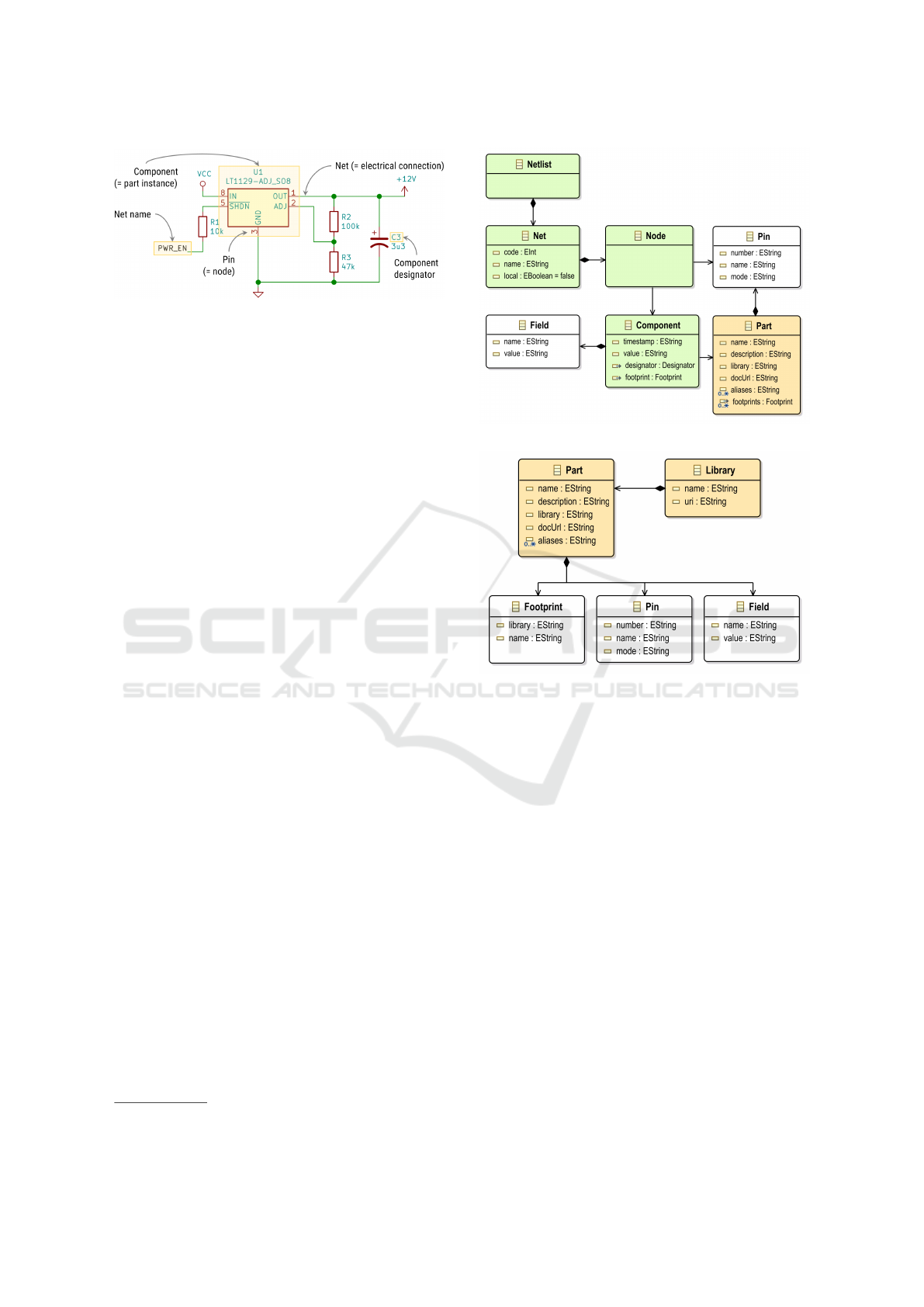
Figure 1: Terminology for common schematic elements.
3.1 Motivation and Foundations
Our metamodel closely follows the representation
used by the popular open-source electronic design
automation (EDA) software suite KiCad
1
. Chapters
11 and 15 of the official Eeschema (the schematic
layout component of KiCad) documentation describe
the generation of netlists and the file format used
by KiCad in greater detail (Charras and Tappero,
2018). The reasons for choosing this format as the
basis for the EDA metamodel are twofold: First,
the free and open-source nature of the KiCad tool
suite ensures that the schematic capture software is
universally available. Secondly, the format combines
two concepts that benefit from a close connection,
the modeling of the actual schematic as well as the
abstract parts underlying the design. Similar textual
representations exist for virtually all EDA software
packages, the OrCAD Capture User Guide includes a
comprehensive overview (Cadence Design Systems,
2016, ch. 20).
Conceptually, a schematic of an electronic circuit
denotes the component symbols for the parts of
the circuit and electrical connections between them.
These connections between components form the
basis for netlists, which list all nets formed by
electrically connected parts (or their connection
points, such as pins or pads on an integrated circuit).
Figure 1 illustrates how these concepts relate to the
graphical representation of circuit diagrams. From
this structural description of electronic circuits the
EMF metamodel for netlists shown in fig. 2 was
derived.
EDA tools frequently include a library of common
components, including their schematic symbols and
information about physical properties such as pin
assignments and their package. These libraries can
also be extended by the designer, to accommodate for
specific parts not available in the generic library.
Figure 3 shows our metamodel for such
component libraries. Parts are grouped inside
uniquely identified libraries and carry information
1
http://www.kicad-pcb.org
Figure 2: Metamodel for netlists.
Figure 3: Metamodel for electronic component part
libraries.
about their physical package and pin assignment, as
well as textual fields stored as key-value pairs.
These key-value pairs can convey arbitrary
additional information about a part or a specific
component instance in a circuit, such as manufacturer
part numbers, links to supplementary documentation,
or simulation models and parameters.
The EDA metamodel has been defined as
an instance of the EMF Ecore meta-metamodel.
An accompanying parser allows to directly load
file-based netlist representations as created by the
KiCad software. This parser transforms the textual
netlist into a proper instance of the EDA metamodel,
which can be supplied as an input to the analysis
framework introduced in the next section.
3.2 Description of Metamodel Elements
Part. A template element that abstractly describes
a single electronic part and its basic properties
(name and description, as well as alternative
names [aliases]).
A Metamodel and Model-based Design Rule Checking DSL for Verification and Validation of Electronic Circuit Designs
317

Library In order to improve usability, EDA tools
commonly group related parts into libraries, e.g.
by function or manufacturer.
Footprint. In order to produce a printed circuit
board (PCB) from a schematic, all components
need to be assigned a footprint, which describes
the physical packaging of the part. Since a single
part may be offered in a variety of packages by its
manufacturer, a single Part model element can
be associated with multiple Footprint element
instances, whereas only a single footprint is
permitted for a concrete component in a circuit.
Pin. A single external connection point for a part,
identified by its ordinal number with respect to the
footprint of the part. A pin is further characterized
by its mode of operation, e.g. output, input,
or power supply pins of a part. Each part
may contain any number of pins, although most
electrical components contain at least two pins
(notable exceptions are e.g. test points used for
quality assurance and debugging purposes, which
only contain a single connection point).
Field. Both library parts as well as components
can carry arbitrary metadata in the form of
key-value pairs, which may be used to convey
additional information about the underlying
circuit element (such as documentation references
or procurement information).
Netlists. The collection of all nets in a circuit.
Net. An electric connection between one or more
nodes. Nets are identified by a numeric code and
may be assigned a unique name. In a hierarchical
schematic, nets may also be designated as local,
i.e. not visible outside the current hierarchy level.
Node. A node is the point where a single pin of a
component makes connection with a net.
Component. A concrete instance of a library part
on a circuit diagram. A component is identified
by its reference designator on the schematic,
usually comprised of a single-letter prefix and a
numeric counter (e.g. C12 for a capacitor; see
IEEE Std 315-1975 for comprehensive reference).
Components are assigned a value, which further
characterizes the component (e.g. the resistance
or capacitance values for passive elements, or the
concrete part name for a library part with multiple
aliases). A unique timestamp allows to accurately
match components, even when their designator
changes, e.g. when the schematic is formatted in a
different layout and designators are re-numbered.
3.3 Use Cases
The EDA metamodel described in this section
forms the basis for the MBDRC validation language
introduced below. However, other use cases besides
circuit validation are possible, for example:
BOM Generation. Since the netlist model contains
information about all components in a circuit, as well
as additional metadata, a bill of materials (BOM) can
be generated from it. The BOM lists all parts in a
circuit, their designators, values, as well as additional
procurement and/or assembly information. Identical
parts can be grouped together to improve readability
and conserve space.
The generation of a BOM is one example for the
class of model-to-text (M2T) transformations that is
possible using the EDA model as input.
Model Versioning. Given a representation of an
electronic circuit as a model at different points in
time, analysis of the evolution of the system over time
in a semantic manner becomes possible (see Selic
(2003, p. 23)). A persistent storage of these models
allows to compare circuits between arbitrary revisions
based on changes in the model elements, similar to
approaches already found in the software modeling
domain.
Furthermore, these snapshots can serve as
baselines, from which different design variants
can be derived; for example to evaluate different
implementation options. Since our metamodel
follows the Ecore meta-metamodel and is based
on the set of Eclipse EMF technologies, model
versioning approaches could be easily constructed
using the EMF Compare
2
feature (see also Brun and
Pierantonio, 2008).
4 MBDRC — A DSL FOR
MODEL-BASED DESIGN RULE
CHECKING
4.1 Foundations
This section introduces a textual domain-specific
language – MBDRC – for validation of electronic
circuits based on the metamodel described above. Its
name stems from the design rule checking (DRC)
activities that form an integral part of the design of
electronic circuits. Conventionally, such checks are
2
https://www.eclipse.org/emf/compare
MODELSWARD 2019 - 7th International Conference on Model-Driven Engineering and Software Development
318

directly integrated into EDA tool packages, with little
room for customization or secondary use outside the
design tool.
We propose to separate the validation of design
rules from the actual EDA tool used to design
the system. This split enables use cases beyond
the classical support of circuit designers in their
daily work: For example, a standalone design
validation can provide automated quality assessments
of electronic designs in a similar fashion to
state-of-the-art software engineering practice in the
field of Continuous Integration. Analysis results
can be visualized as part of a product quality
dashboard, enabling a high-level overview of a
system’s development progress.
Furthermore, a stand-alone validation approach
based on open technologies can help to alleviate
the effects of vendor lock-in caused by the use of
proprietary software solutions.
4.2 Language Definition and Elements
The MBDRC language is a textual domain-specific
language defined using the Eclipse Xtext language
engineering toolkit.
3
It utilizes the EDA metamodel
from the previous section to express rules used to
assess the validity of a given electrical circuit design.
Overall Structure. As the top-level entity, an
MBDRC script file may contain an arbitrary number
of named rules. These rules provide a semantic
grouping for validation expressions, against which a
given netlist should be validated.
Validation expressions comprise a number of
first-order logic expressions over the elements and
attributes of the EDA metamodel introduced in the
previous section.
Validation Expressions. Rules are composed of
one or multiple quantified first-order predicates,
denoted by the forall and exists keywords in
the MBDRC language (corresponding to the ∀ and
∃ quantifiers). If a rule contains more than one
quantifier, the overall rule is considered the logical
conjunction of these quantified expressions.
Every quantified expression may reference an
arbitrary number of target variables, which will be
bound during evaluation by the interpreter. The list
of target variables immediately follows the quantifier
keyword (see the following section for concrete
examples of the syntax). Each variable is associated
with a type, either component, pin, or net, and must have
3
https://www.eclipse.org/Xtext
a unique identifier. These variable definitions are
collected in the sets C, N, P or components, pins, and
nets for each quantified expression.
Individual quantified expressions are evaluated by
binding the quantified variables to all combinations
of components, nets, and pins of the netlist. All
constraints in the quantified expression are then
evaluated using this valuation; if multiple constraints
are specified, the overall result is obtained as their
logical conjunction.
The actual constraints are propositional logic
formulae (using ∨, ∧,→, ¬), with support for equality
and inequality comparisons (<, >, ≤, ≥, =, 6=), as
well as property expressions on target variables,
function calls, and array types.
Validation expressions can be scoped to only
specific subsets of a netlist by specifying a where
expression. During evaluation, only variable
assignments that fulfill the scoping condition will be
further validated against the rule body. By selecting
appropriate scope conditions, the rule body can be
simplified in order to improve readability and rule
evaluation performance. Besides this main function
of narrowing the scope for the rule body, the where
clause also allows for a traversal of model structure,
in a similar fashion to joins in SQL. This feature is
further described in the next subsection.
Type Checking. Expressions in the MBDRC
language are strongly typed and continuously type
checked during the development of the script inside
the editor as well as during the interpretation of the
script.
The language supports both primitive types
(boolean, integers, strings), complex types (as defined
by the EDA metamodel), as well as sets of these.
Function expressions are statically typed, i.e. their
parameter and return values types must be known at
design time. Overloads of different return types are
not currently supported in the DSL.
4.3 Rule Script Execution
The MBDRC domain-specific language forms the
basis for an automated validation of a given netlist
against a set of design rules. While in theory
the analysis could be performed inside standalone
validation tool, we envision its use in a more complex
workflow. Therefore, the MBDRC analysis has been
integrated into the model-based analysis framework
previously described in Rumpold et al. (2017); Pröll
et al. (2018). The addition of the EDA metamodel
proposed in the previous section adds a new modeling
domain to the set of domain specific modeling
A Metamodel and Model-based Design Rule Checking DSL for Verification and Validation of Electronic Circuit Designs
319
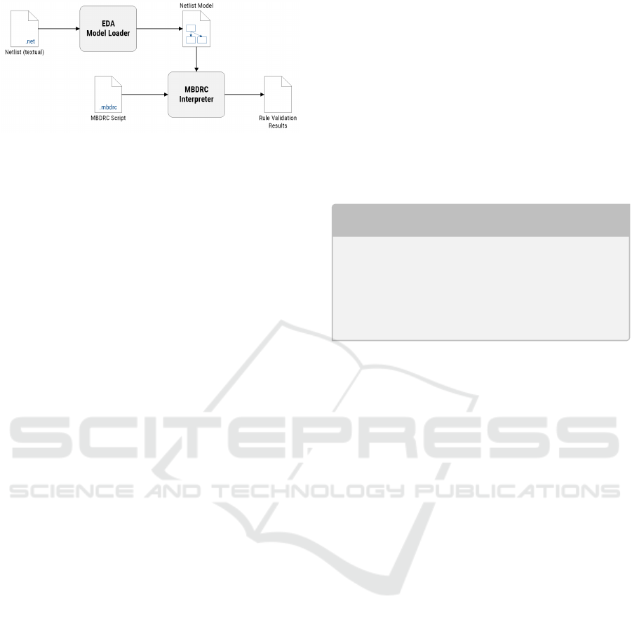
Figure 4: Execution workflow for an MBDRC analysis.
languages already included in the base framework
(see Rumpold et al. (2017, fig. 1) for details).
The MBDRC analysis is available as one analysis
unit along the execution graph to be processed by the
analysis framework. It depends on a previous loader
step, which transforms the textual representation of
the input netlist into a proper domain model, and
produces one or multiple analysis result objects.
These describe the success or failure of each MBDRC
rule that was validated, including detailed information
about rule violations. Figure 4 illustrates the flow of
information and dependencies between the steps of
MBDRC validation.
The results can then be further processed,
depending on the use case for the analysis: In
an interactive setting, it might be desirable to
highlight each circuit element that violates any
design rules to aid the designer in fixing these
problems. If the analysis is used to produce
a quality report document, a more coarse-grained
listing of all passed or failed design rules can
be generated, omitting information about individual
component-level elements. Generating such reports
can be delegated to downstream model-to-text steps
in the execution flow, to promote a proper separation
of concerns between analysis modules.
4.4 Application Examples
The following section aims to illustrate the
capabilities of the MBDRC language by applying
it to two common tasks found in the EDA design
process.
This selection of examples in this paper is by
no means exhaustive, but rather seeks to provide an
overview of the language elements and their possible
applications.
Validation of Documentation and Manufacturing
Information
Besides the structural information, the EDA
metamodel introduced in the previous section also
allows to attach metadata to each component in a
circuit, or to the underlying library part, in the form
of arbitrary key-value fields.
One use case for this information is to verify the
availability of parts from a distributor and monitor
the life cycle status of critical components as part of
obsolescence management (see IEC 62402:2007 as an
example for a relevant international standard).
The following MBDRC code snippet enforces that
each component must be annotated with a distributor
or manufacturer part number, unless it is actively
marked as not being a critical part for the BOM (bill
of materials):
Listing 1: MBDRC code for validation of procurement
metadata.
rule B OMValidat i o n {
fo ral l ( c o mpo n ent c ) {
// Ev er y c o m pon e nt mu st de c lar e its
// man u f a ctu r e r / di s t rib u t or pa rt nu m be r
co n str a i nt c . b o m_c r i t ica l != " no " ->
(c. d i s tr _ no != " " || c . m anf _no != "" );
}
}
Listing 1 illustrates the basic structure of an
MBDRC script: Each validation rule, identified
by an arbitrary name, may contain one or more
quantified expressions to specify the target model
elements. Each quantified validation expression
defines constraints to be verified against matching
elements from the netlist model under test. Both
block and single-line comments may be added to
the script in a syntax familiar from the C or Java
programming languages.
Electrical Rules Checking
As a more comprehensive demonstration of the
capabilities of the MBDRC language, this example
shows the implementation of simple electric rules
checks as a composite MBDRC rule. These checks
are commonly found in EDA tools to prevent logical
errors during design of an electronic circuit and serve
to validate the design during the schematic capture
phase of the product life-cycle.
ERC rules for example guarantee that no two
power sources are directly connected, or that
components are not shorted out (which effectively
renders them useless in the circuit, since they are
bypassed). Most commercial EDA packages include
a variant of this check; fig. 5 depicts the configuration
of the pin compatibility matrix in the KiCad ERC
checker as one representative example.
Listing 2 shows the implementation of a subset of
these checks in the MBDRC language. The example
demonstrates some of the more advanced features of
the DSL:
MODELSWARD 2019 - 7th International Conference on Model-Driven Engineering and Software Development
320

• Multiple quantified expressions can be combined
to form composite rules. The overall rule
evaluation result is formed by taking the logical
conjunction of each quantified expression in the
rule.
• where (p1.net == p2.net): Scope filters can
selectively apply constraints to model elements
matching a filter expression. Complex property
expressions (references to other model elements;
in this example the net associated to a single pin)
allow for comfortable model traversal similar to
joins in relational databases.
• p2.mode in ["output", "power_out", "3state"]: The
language supports sets of primitive types and
membership testing for element properties, as a
syntactical shorthand to improve readability.
• card(p.nets) <= 1: Function expressions allow
computation of values from model properties
(the example determines the number of nets a
pin is connected to as the cardinality of the
set). The set of available functions is currently
fixed, future research may add the possibility
of declaring additional functions as part of the
MBDRC language.
• not exists: In order to improve readability, the
result of quantified expressions may be negated.
This does not change the expressiveness of the
language, since the negation might also be pushed
inside the expression (compare first-order logic:
¬∃x.P(x) ⇔ ∀x.¬P(x))
• severity=info and message "Pin mode unspecified": Rules
may specify a custom level of severity (info,
warning, error) as well as a informative message
to be displayed to the user, if the rule is found to
be violated during evaluation.
Figure 5: ERC pin compatibility validation rules provided
by KiCad.
Listing 2: MBDRC code for validation of electrical
connection rules.
rule ER C _ Pin T y p es {
// Con n ect e d p in s mu st ha ve co m p ati b l e m od es
fo ral l ( pin p1 , pin p2 ) wh ere ( p1 . net == p2 . n et ) {
co n str a i nt p1 . mo de == " p o w er_ o ut " ->
!( p2 . mode in [ " out put " , " po w er_ o ut " , " 3 st a te " ]);
co n str a i nt p1 . mo de == " o u tp u t " -> p2 . m od e != " ou t pu t " ;
co n str a i nt p1 . mo de in [" o p enC ol " , " ope nEm " ] - >
!( p2 . mode in [ " out put " , " po w er_ o ut " ]) ;
}
// Pins m a rk e d as ’ do not co nn ec t ’ m us t no t be
// at t a ch e d to any ot her net in the sc h e mat i c
fo ral l ( pin p , net n ) wh e re ( n == p . net ) {
co n str a i nt p . mo de == " No t C on n e c ted " -> c ar d (n) <= 1;
}
// Warn for u n spe c i fie d p in m ode s
not e x is t s ( pin p ) se v eri t y = w ar n {
me ssa g e " Pin mo de un s p eci f i ed ";
co n str a i nt p . mo de == " u nsp c ";
}
}
5 CONCLUSION
This paper has introduced two key results: First,
we have proposed a general-purpose metamodel for
electronic circuits derived from an industry-standard
netlist representation. The metamodel allows
capturing structural information about electronic
circuits, as well as metadata and library information
about the parts used in these circuits.
Subsequently, we have described a textual
domain-specific language for the analysis and
validation of circuits represented as instances of
this metamodel. Several application examples
demonstrate the language features as well as the
DSL’s suitability as a complement to the validation
functionality found in common EDA tools.
We foresee that our approach can supplement
the established design workflow for electronic
circuits, by uncoupling the checking of design and
electrical rules from any concrete EDA software
suite. This additional freedom allows for easier tool
interoperability and enables new use cases for these
analyses.
Future Work
Based on our preliminary research introduced in this
work, we envision a number of possible scenarios
for further research, expanding the scope both
towards more abstract system-level views, as well as
sub-circuit level design activities.
Generation of Validation Code. The first
prototype of the MBDRC DSL uses a separate
A Metamodel and Model-based Design Rule Checking DSL for Verification and Validation of Electronic Circuit Designs
321

parser to validate the rules defined in an MBDRC
script against a concrete netlist. This approach
facilitates the rapid co-evolution of the language
syntax and its associated semantics, but does not
fully utilize the power of the model-based approach.
Instead, validation code for a given set of rules can
be generated directly. The set of technologies for
implementation of the first prototype of the DSL was
chosen with this extension in mind: Xtext offers rich
support for generating Java (among other languages)
code from a DSL script (see Bettini, 2016, ch. 5).
Physical Layout Validation. While the current
implementation of the MBDRC language is based on
the metamodel for the abstract circuit representation
embodied by netlists, the same concepts hold for
the validation of physical circuit layouts. Here, the
validation focuses on the positioning and electrical
connections between components on a printed
circuit board (PCB). Common questions during PCB
design revolve around minimum clearance between
adjacent tracks on the board, physical dimensions of
components, or violations of manufacturing process
capabilities (e.g. minimum drill sizes for holes or
minimum track widths that can be manufactured).
The EDA metamodel can be extended to also
include the physical positioning of components on
a printed circuit board, the tracks that correspond to
nets, as well as the physical dimensions of the board
and the components to be placed on it. By adding
appropriate mathematical operations to the MBDRC
language, it can then be used to answer these physical
design questions.
Test Plan Generation. Our last suggestion for
further research focuses on the test of hardware
components. Based on the model representation,
as well as higher-level descriptions of requirements
and associated test goals, we envision a strategy for
planning of testing activities: By establishing a model
link between requirements, test goals, as well as the
actual components under test in a single integrated
model, test cases may be derived that fulfill these test
goals. One example might be the goal of verifying
the correct function of fault tolerance mechanisms by
means of fault injection. The circuit model provides
the necessary information about the available signals
as well as potentially affected components, while the
traceability of the model allows to identify affected
software components. The integrated view on both
these domains allows for a clearer picture of the
dependencies between components, as well as the
necessary development steps in order to achieve
certain test goals.
REFERENCES
AUTOSAR (2017). Specification of ECU Resource
Template. Specification 060.
Bettini, L. (2016). Implementing Domain-Specific
Languages with Xtext and Xtend. Packt Publishing,
Birmingham, Mumbai, 2nd edition.
Brun, C. and Pierantonio, A. (2008). Model Differences
in the Eclipse Modelling Framework. CEPIS
UPGRADE, IX(2):29–34.
Cadence Design Systems (2016). OrCAD Capture User
Guide. Technical Documentation.
Charras, J.-P. and Tappero, F. (2018). Eeschema
Reference Manual. http://docs.kicad-pcb.org/master/
en/eeschema.html.
Fischbach, R., Heinig, A., and Schneider, P. (2014).
Design rule check and layout versus schematic for
3D integration and advanced packaging. In 2014
International 3D Systems Integration Conference
(3DIC), pages 1–7, Kinsdale, Ireland. IEEE.
IEC 61690-2:2000 (2000). Electronic design interchange
format (EDIF) - Part 2: Version 4 0 0. International
Standard IEC 61690-2:2000, International
Electrotechnical Commission, Geneva, CH.
IEC 62402:2007 (2007). Obsolescence management
- Application guide. International Standard
IEC 62402:2007, International Electrotechnical
Commission, Geneva, CH.
IEEE Std 315-1975 (1975). Graphic Symbols for Electrical
and Electronics Diagrams. Standard 315-1975,
Institute of Electrical and Electronics Engineers.
Nagel, L. W. (1975). SPICE2: A Computer Program
to Simulate Semiconductor Circuits. PhD Thesis,
EECS Department, University of California, Berkeley,
Berkeley, CA, USA.
Pelz, G. (1992). An interpreter for general netlist design
rule checking. In Design Automation Conference,
1992. Proceedings., 29th ACM/IEEE, pages 305–310.
IEEE Comput. Soc. Press.
Pröll, R., Rumpold, A., and Bauer, B. (2018).
Applying Integrated Domain-Specific Modeling
for Multi-concerns Development of Complex
Systems. In Pires, L. F., Hammoudi, S., and Selic,
B., editors, Model-Driven Engineering and Software
Development, pages 247–271. Springer International
Publishing.
Quarles, T., Newton, A. R., Pederson, D. O., and
Sangiovanni-Vincentelli, A. (1993). SPICE3 Version
3f3 User’s Manual. Department of Electrical
Engineering and Computer Science, University of
California. Berkeley, CA.
Rumpold, A., Pröll, R., and Bauer, B. (2017).
A Domain-aware Framework for Integrated
Model-based System Analysis and Design. In
5th International Conference on Model-Driven
Engineering and Software Development, pages
157–168. SciTePress.
Selic, B. (2003). The pragmatics of model-driven
development. IEEE Software, 20(5):19–25.
MODELSWARD 2019 - 7th International Conference on Model-Driven Engineering and Software Development
322
