
Modelling the Behaviour of Context-aware Systems: State-of-the-Art
Analysis and Introduction of a Customized UML Profile
Patrick Rosenberger
a
, Detlef Gerhard
b
and Stefan Dumss
c
Institute of Engineering Design and Product Development, TU Wien, Getreidemarkt 9/307, 1060, Vienna, Austria
Keywords: Context-aware Systems, Systems Modelling, Unified Modeling Language, Context-aware System Analysis,
Context-aware System Design.
Abstract: The usage of smart devices in combination with the extensive deployment of sensors enables the development
of systems that can recognize their environment and act accordingly. These so-called context-aware systems
allow the automation of the user interactions by providing the desired functionality based on an understanding
of the users' current context. During the development of such systems, the context-related system properties,
the contextual functionalities, as well as the underlying contexts must be defined. UML models are a valuable
tool for such tasks. In this publication, the previous research regarding the graphical representation of context-
aware systems is analysed. It is shown that the modelling of contextual behaviour is still not addressed
sufficiently. To counter this issue, contextual design templates are introduced. These templates allow the
visualization of different system properties by combining the UML standard notation with a newly introduced
notation for stating contexts. Further, a profile for the modelling of contexts and related system functionalities
is presented.
1 INTRODUCTION
Graphical models are an important tool of software
development projects. They allow to handle the ever-
increasing complexity by mapping a system’s structure,
its behaviour, and other properties at various levels of
abstraction (Weilkiens, 2014). In that regard,
modelling languages define the rules and guidelines
that are needed for their creation (Ohst et al., 2003).
Over the previous decades, the Unified Modelling
Language (UML) (OMG, 2015) has prevailed as the
leading standard for software systems (Grönniger,
2010). One of its strengths lies in the high number of
diagrams and elements the language defines.
Nevertheless, it is not feasible for any modelling
language to provide elements for all system properties
in all domains. To keep a manageable size and still
meet the requirements of specialized use cases, the
UML defines an interface for customized extensions
(Rupp and Queins, 2012). By introducing new profiles,
users can adapt the language to their needs (OMG,
2015).
a
https://orcid.org/0000-0002-5504-0267
b
https://orcid.org/0000-0002-3266-7526
c
https://orcid.org/0000-0001-8679-0821
One domain that cannot fully be modelled with the
UML standard notation are context-aware systems
(Perera et al., 2014). To address this issue, different
contextual profiles have been developed. Nevertheless,
it is still not possible to state all behaviour-related
aspects as the previous approaches only focused on
structural models, specific issues, or individual
diagram types. This publication introduces a general-
purpose extension for modelling the behaviour of
context-aware systems. Section 2 starts with a state-of-
the-art analysis of previously proposed extensions.
Afterwards, section 3 presents an industrial use case.
In the following chapters, excerpts of this use case are
presented to visualize practical examples of the
theoretical concepts. Section 4 discusses the structure
of contexts and introduces a notation for their
representation in UML diagrams. In section 5, different
design templates are discussed. These templates
combine the UML standard notation with the
previously introduced notation to model various
aspects of context-aware systems. Nevertheless, not all
behavioural properties can be described that way.
Rosenberger, P., Gerhard, D. and Dumss, S.
Modelling the Behaviour of Context-aware Systems: State-of-the-Art Analysis and Introduction of a Customized UML Profile.
DOI: 10.5220/0007685805190526
In Proceedings of the 7th International Conference on Model-Driven Engineering and Software Development (MODELSWARD 2019), pages 519-526
ISBN: 978-989-758-358-2
Copyright
c
2019 by SCITEPRESS – Science and Technology Publications, Lda. All rights reserved
519

Therefore, section 6 introduces an adapted UML
profile that allows to visualize contexts as well as the
still missing behavioural characteristics in various
diagram types. Based on the use case of section 3,
section 7 finishes by presenting a case study. It is
shown how the previously introduced design templates
and profile can be applied during the development of a
context-aware system.
2 STATE OF THE ART
In the previous years, different authors have introduced
contextual UML extensions. Almutairi et al. (2012)
presented a heavy-weight extension for security-
related requirements in use case diagrams. Another
heavy-weight extension was proposed by Choi (2007).
This extension does not only introduce new elements,
but also three new diagram types that are only partly
compatible with the rest of the standard notation. Choi
and Lee (2012) proposed a light weight extension for
the visualization of context-aware systems. While
focusing on use case diagrams, they describe how the
stereotypes can be used to display contextual system
requirements. Ayed and Berbers (2006) introduced a
modelling approach that separates the contextual
functionalities from the base system. Following this
separation of concerns simplifies the development
process as the interaction only takes place through
defined interfaces. Ayed et al. (2007) extended the
previously described approach by adding a process
model for the development of context-aware systems.
Benselim and Seridi-Bouchelaghem (2012) introduced
a profile that focuses on the visualization of class
diagrams and contains two categories of stereotypes.
The first category is focused on describing contexts,
the second category is focused on the type of
association between different classes. Fuentes et al.
(2008) introduced a profile for the aspect-oriented
modelling of context-aware systems. The objective of
this approach is to enable the extraction of executable
code from the graphical models. Grassi and Sindico
(2007) followed the principles of the service-oriented
architecture and implemented a profile that enables the
separation of concerns. Disintegrating the contextual
extensions from the original system allows to design
the base system using standardized tools and to
introduce contextual features through defined
interfaces. In contrast to the previous publications,
Omasreiter and Metzker (2004) did not introduce a
profile, but they demonstrated how the standard use
case diagram can be used for the modelling of context-
aware use cases. Sheng and Benatallah (2005)
introduced the ContextUML profile, so far, the most
referenced extension for the graphical modelling of
context-aware systems. The focus lies on the
identification and the visualization of the relevant
structural properties of context-aware systems, which
includes contexts, contextual sources, and contextual
functionalities. Simons (2007) introduced a context
modelling profile that is focused on class diagrams.
The objective is to allow the creation of understandable
models with little experience. Van den Bergh and
Coninx (2005) presented the context-sensitive user
interface profile that focuses on the effects on the user
interface.
Despite the variety of proposed approaches, a
comprehensive profile for visualizing the behaviour of
context-aware systems is still missing. The analysis
shows that most research efforts are focused on
structural aspects and that behavioural models are still
a side issue. Further, many of the proposed behavioural
extensions are specialized on one diagram type or use
heavy-weight extensions that are only partly
compatible with the rest of the UML standard notation.
3 USE CASE
In the next chapters, the application of the introduced
design templates and stereotypes is demonstrated using
an industrial use case. As a supplier for the automotive
industry, the analysed injection moulding company
produces parts for various customers. Although the
production processes are automated to a high degree,
the workers are responsible for setting up the machines,
providing the raw material, controlling the quality of
the products, and packaging them for dispatch. As
industrial partner in the EU Horizon 2020 research
project FACTS4WORKERS, the company is – among
other things – improving its software systems.
Thereby, a context-aware information system is
introduced that provides the workers with the required
information based on an understanding of their context.
The development of this system is split into two parts.
First, a context-unaware version is deployed and
tested. Afterwards, the system is upgraded with a
variety of contextual features. Thereby, the design
templates and the profile of this publication are
applied.
4 CONTEXTS AND THEIR
NOTATION
Contexts are the key elements of context-aware
systems (Rosenberger and Gerhard, 2018b). A con-
MODELSWARD 2019 - 7th International Conference on Model-Driven Engineering and Software Development
520
text represents the description of a situation in a format
a system can understand and process. Thereby, only
situations that are relevant to the interaction between
the user and the system are considered contexts
(Rosenberger and Gerhard, 2018a). Each context
consists of one or more contextual attributes that are
used for the identification of the context. Among
others, possible attributes are a user's name (e.g. John
Doe) or her/his current location (e.g. at the warehouse).
Further, each contextual attribute can be related to a
specific contextual type. These types can be
understood as categories that cluster all attributes with
the same properties (e.g. all locations). For a detailed
discussion of this topic, please refer to Rosenberger
and Gerhard (2018a).
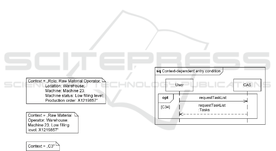
To model contexts, three different notations can be
used. The type-attribute notation states all attributes of
a specific context as well as the related types. While
this provides a comprehensive description, it requires a
substantial amount of space and can overload diagrams
with a low level of detail. The attribute notation only
states the attributes and therefore provides a shortened
description. Nevertheless, the omission of the types
can lead to misunderstanding. For example, the
number X1219857 can be used to identify a worker, a
machine, or a production order. The ID notation only
states a context's ID as a placeholder. While this
requires little space, additional tools for stating a
context's attributes and types are necessary.
Figure 1: Type-attribute notation (top), attribute notation
(middle), ID notation (bottom).
Not in all cases, the attributes are not known
beforehand, but rather they are learned by the system
during its usage. In these cases, the type-attribute
notation and the attribute notation are not suited.
Rather, it can either be stated that the context will be
learned autonomously by the system. Alternatively, the
ID notation can be used to make this statement at a
supporting tool like the context-activity matrix
(Rosenberger et al., 2018).
5 DESIGN TEMPLATES
The design templates combine the UML standard
notation with the notation of chapter 4 to model
contextual system properties. In the following, only the
context-related elements are described and explained,
as it is assumed that the reader is aware of the UML
standard notation. Due to the restricted extension of
this publication, only the ID notation will use in the
following models. Nevertheless, also the type-attribute
notation and the attribute notation can be applied.
5.1 Context-dependent Entry
Conditions
Context-dependent entry conditions prevent the
execution of a combined fragment, if the stated context
is not present. In sequence diagrams, this is modelled
by defining the corresponding context as the entry
condition for the combined fragment. It is important to
note that context-dependent entry conditions can only
be used, if the combined fragment allows entry
conditions. The following example shows the fragment
"option", whereby a worker is requesting his/her tasks
for the day. If the context "C34" is present (shift start,
authentication OK, training level sufficient, etc.), the
fragment is executed, otherwise it is passed.
Figure 2: Example of a context-dependent entry condition.
5.2 Context-dependent State Invariants
Context-dependent state invariants are runtime
constraints that impact the interaction between the
participants. In sequence diagrams, this is modelled by
defining the corresponding context as the state
invariant. The following example shows a maintenance
worker that is requesting an overview over all open
machine errors. Thereby, the interaction can only start,
if the context "C32" (maintenance worker,
authentication OK, etc.) is present.
Modelling the Behaviour of Context-aware Systems: State-of-the-Art Analysis and Introduction of a Customized UML Profile
521
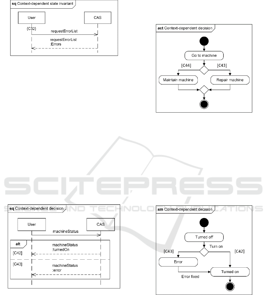
Figure 3: Example of a context-dependent state invariant.
5.3 Context-dependent Decisions
Context-dependent decisions describe a choice
between several paths that depends on the context. If
the process flow reaches such a decision, the current
context is evaluated and the process continues at the
corresponding edge.
5.3.1 Sequence Diagrams
In sequence diagrams, context-dependent decisions are
modelled using the combined fragment "alternative" in
combination with context-dependent entry conditions.
The following example shows a user requesting a
machine status. The system evaluates different
characteristics of the machine (heat level, oil level,
etc.) and determines its health. Based on the results (the
current context), different responses are sent to the
user.
Figure 4: Example of a context-dependent decision in a
sequence diagram.
5.3.2 Activity Diagrams
In activity diagrams, context-dependent decisions are
visualized using decision nodes. The following
example shows a maintenance worker who approaches
a machine. Whether the worker has to repair the
machine or just needs to maintain it, depends on the
machine's current status. Like for the previous
example, the context-aware system assesses the status
of the machine and returns the result the result the
worker. Finally, the worker either repairs the machine
or maintains it.
Figure 5: Example of a context-dependent decision in an
activity diagram.
5.3.3 State Machine Diagrams
In state machine diagrams, context-dependent
decisions are visualized using the UML element
decision. The following example shows a machine that
is started. Thereby, the machine can either start
normally, or an error can occur. During the process, the
system evaluates different characteristics of the
machine to determine its health. Depending on the
results, the corresponding the state is set.
Figure 6: Example of a context-dependent decision in a
state machine diagram.
5.4 Context-dependent State Changes
Context-dependent state changes are transition
between different states that are caused by the
appearance of a context. In state machine diagrams,
this is modelled by defining the corresponding context
as the trigger for the transition. The following example
shows a machine that is idle and ready to produce parts.
MODELSWARD 2019 - 7th International Conference on Model-Driven Engineering and Software Development
522
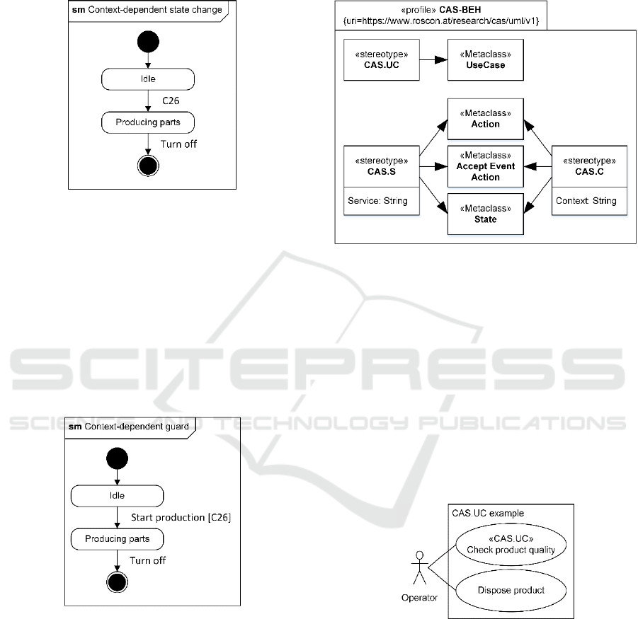
The transition from "idle" to "producing parts" takes
place as soon as context "C26" becomes present
(production order assigned, worker at the machine,
etc.).
Figure 7: Example of a context-dependent state change.
5.5 Context-dependent Guards
Context-dependent guards visualize that the transition
between different states can only take place, if the
stated context is present. In state machine diagrams,
this is modelled by defining the corresponding context
as the guard for the transition. The following example
shows a state machine diagram of a machine in idle
mode. After triggering the production start, the current
context is evaluated. Only if the context "C26" is
present, the machine starts producing parts.
Figure 8: Example of a context-dependent guard.
6 CONTEXT-AWARE UML
PROFILE
Despite their expressive power, the design templates
are not capable of modelling all contextual properties.
In particular, they do not allow to state the contextually
assisted use cases, the contextual services, or the
related contexts. Therefore, a UML profile is
introduced that provides the required stereotypes to
model these still missing behavioural characteristics.
Using this profile in combination with the design
templates allows to fully visualize the behavioural
characteristics of a context-aware system.
Figure 9: CAS-BEH profile.
6.1 «CAS.UC»
The stereotype «CAS.UC» is used to identify the
contextually assisted use cases. The following example
shows an overview over the operator's activities during
the quality control. The activity "check product
quality" is assisted contextually. Therefore, the use
case is labelled with the stereotype «CAS.UC». In
contrast, the second use case "dispose product" does
not require any contextual support. It is important to
notice, that this does not exclude interactions with the
system in general. Instead, it only clarifies that the
support is not contextual.
Figure 10: Example «CAS.UC».
For larger or recurring activities, it can be
advantageous to outsource the contextual parts into
separate use cases using the "include" or "extend"
relationships. This allows a clear distinction between
the contextually assisted and the not contextually
assisted activities. In the following example, the
regular use case "refill raw materials" is expanded with
the two contextual use cases "determine raw materials"
and "purchase raw materials".
Modelling the Behaviour of Context-aware Systems: State-of-the-Art Analysis and Introduction of a Customized UML Profile
523
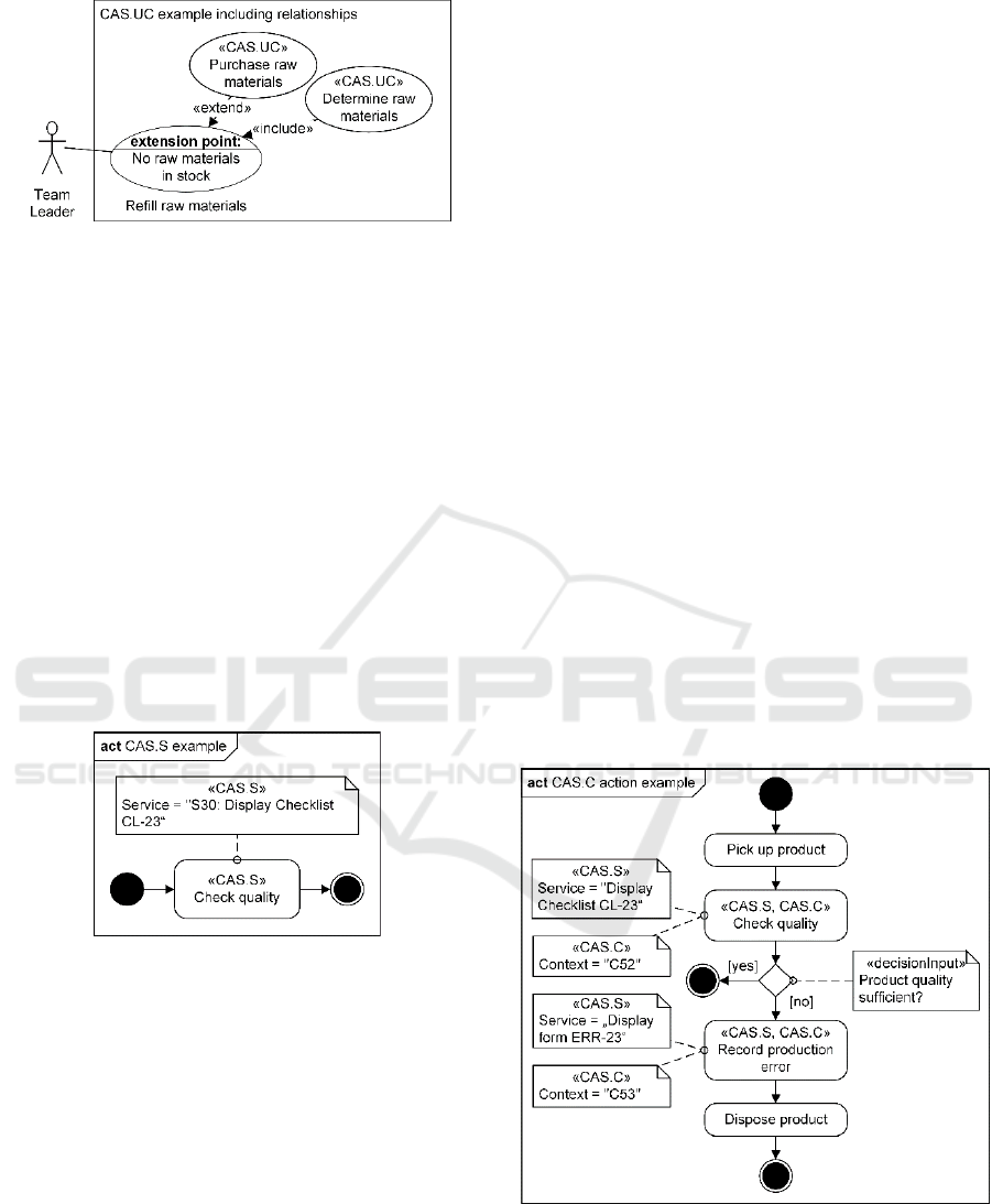
Figure 11: Example «CAS.UC» with «include» and
«extend» relationships.
6.2 «CAS.S»
The stereotype «CAS.S» is used to highlight activities
that are assisted by a context-aware system. Further, a
brief description of the provided service can be given
using the tagged value "Service". It is recommended to
keep the statement short and simple to prevent
overloading the model. If necessary, longer
descriptions should be outsourced to more appropriate
tools, like the context-activity matrix (Rosenberger et
al., 2018). Doing so, it might be helpful to assign each
service with a unique ID. The following example
shows a worker who checks the product quality. As
stated, the activity is assisted by the context-dependent
display of the checklist CL-23. Further, the contextual
service can be identified using the ID "S30".
Figure 12: Example «CAS.A».
6.3 «CAS.C»
The stereotype «CAS.C» is used to model contexts. It
can be applied to actions and accept event actions in
activity diagrams as well as to states in state machine
diagrams. The following characteristics must be
considered:
A central requirement of contexts is their
uniqueness. As described by (Rosenberger et al.,
2018), a context can and must only describe one
specific situation. If the contexts are not unique, the
system will not be able to differentiate between
distinct situations.
The multiplicity of contexts states that different sets
of contextual attributes can describe equal
situations. For example, a machine is not
functioning properly in case of a technical failure
as well as when the product dimensions did not
match the requirements. Further, different contexts
can require the same contextual service. As an
example, different users at different locations can
require a navigation to the same destination.
Borders and regions are an important aspect of
continuous attributes (e.g. the position of a user or
the time), as they allow to define areas in which all
contextual attributes describe the same context.
Borders define the boundary values, whereby all
values within are describing the same context. An
example would be “from 8:00 am to 4:00 pm” with
“11:32 am” as acceptable value. In case of regions,
the acceptable area is stated. An example would be
the region “warehouse”. Here, all positions inside
the warehouse belong to the same context.
6.3.1 Actions
In activity diagrams, the contexts of contextually
assisted actions are stated using the stereotype
«CAS.C». The following example shows the quality
control actions performed by the machine operator.
Thereby, he/she is assisted autonomously based on the
systems understanding of the user's context (C52:
machine operator, production order assigned, worker
at the machine, etc.; C53: machine operator, part
faulty, etc.) as well as his/her needs.
Figure 13: Example «CAS.C» labelling an action.
6.3.2 Accept Event Actions
In activity diagrams, contextual accept event actions
are used to state that the start of a process depends on
MODELSWARD 2019 - 7th International Conference on Model-Driven Engineering and Software Development
524
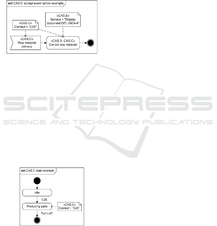
the presence of a context. In the following model, the
raw material control process starts after the appearance
of the context "C58" (raw material delivery, warehouse
operator at the warehouse, etc.). According to the
principle of multiplicity, a context can be used to
identify different actions, if the provided contextual
service is identical for all elements. This is modelled
by assigning the same contextual note to all elements.
Figure 14: Example «CAS.C» labelling an accept event
action.
6.3.3 States
Although each context is also a state, not all states are
contexts. As stated in chapter 4, only situations with
relevance to the interaction between a user and the
system are considered as contexts. Therefore, the
stereotype «CAS.C» is used in state machine diagrams
to identify states that are also contexts. The following
example shows the contextual state "producing parts"
(C26: production order assigned, worker at the
machine, etc.). In contrast, the state “idle” is not linked
to any contextual assistance and therefore not labelled.
Compared to the design template "context-dependent
state change", the stereotype «CAS.C» visualizes that
the context not only triggers the state change, but that
the context is present as long as the system remains in
this state.
Figure 15: Example «CAS.C» labelling a state.
7 CASE STUDY
The following chapter describes the application of the
previously introduced design templates and profile
during the analysis and design of a context-aware
system. The case study is based on the industrial use
case of section 3 and follows the process model of
Rosenberger et al. (Rosenberger et al., 2018).
According to this model, the contextual systems
analysis consists of three steps that are performed in
addition to the analysis of the base system. Thereby,
the results of each stage are visualized using the profile
of section 6. Afterwards, a detailed system design is
elaborated that states the contextual system properties.
This design forms the basis for the following
development acitivities.
The contextual systems analysis starts with the
identification and documentation of the contextually
assisted user activities. Use case diagrams are created
and the stereotype «CAS.C» is used to highlight the
identified use cases. Two of these models are shown in
section 6.1. Additionally, activity diagrams are created,
whereby the contextually assisted actions are
highlighted using the stereotype «CAS.S». In the
second step, the contextual services are defined. These
services are provided by the system after recognizing a
context. For each assisted action, the corresponding
service is stated using the tagged value “Service”.
Figure 12 shows an example of the activity diagrams
that are created during this step. Finally, the contexts
are identified and modelled. Thereby, the stereotype
«CAS.C» and the tagged value “Context” are used to
visualize the individual contexts. To keep the diagrams
clear, only the ID notation is used. Figure 13 and 14
show two examples of the final activity diagrams.
After finishing the system analysis, the complete
system is designed. This includes the creation of
different structural and behavioural diagrams, whereby
only the behavioural aspects are addressed by this
publication. These diagrams are created with the help
of the design temples of section 5 and the stereotypes
of section 6. The figures 2 to 8 and figure 15 show
examples of the different models.
8 CONCLUSION AND FURTHER
RESEARCH
In general, graphical models are a crucial tool for the
development of modern software systems. Especially
for the development of context-aware systems, they are
vital to handle the inherent complexity. Currently no
modelling language provides the required elements to
Modelling the Behaviour of Context-aware Systems: State-of-the-Art Analysis and Introduction of a Customized UML Profile
525

visualize the behaviour of such systems. Nevertheless,
the UML already covers a wide spectrum of elements
and has a defined interface for extending the standard
notation. To address the still open research question,
this publication introduced different design templates
and a UML profile. Using these tools allows
expressing the behavioural characteristics of context-
aware systems in a clear and understandable way.
Therefore, we encourage to use the presented case
study as a reference for developing own models.
While the application of the proposed design
templates and profile in the stated use case was a
success, a large-scale evaluation is still missing. To
assess the approach more extensively, different
context-aware systems will be designed with help of
the proposed extension. Having a brother set of use
case applications will also provide a variety of example
implementations that other modellers can rely on.
REFERENCES
Almutairi, S., Bella, G. and Abu-Samaha, A. (2012),
"Specifying security requirements of context aware
system using UML", Seventh International Conference
on Digital Information Management (ICDIM), IEEE, pp.
259-265.
Ayed, D. and Berbers, Y. (2006), "UML profile for the design
of a platform-independent context-aware applications",
Proceedings of the 1st workshop on Model Driven
Development for Middleware (MODDM'06), ACM, pp.
1-5.
Ayed, D., Delanote, D. and Berbers, Y. (2007), "MDD
approach for the development of context-aware
applications", International and Interdisciplinary
Conference on Modeling and Using Context, Springer,
Berlin, Heidelberg, pp. 15-28.
Benselim, M. S. and Seridi-Bouchelaghem, H. (2012),
"Extended UML for the development of context-aware
applications", International Conference on Networked
Digital Technologies, Springer, Berlin, Heidelberg, pp.
33-43.
Choi, J. (2007), "Context-driven requirements analysis",
International Conference on Computational Science and
Its Applications, Springer, Berlin, Heidelberg, pp. 739-
748.
Choi, J. and Lee, Y. (2012), "Use-case driven requirements
analysis for context-aware systems", Computer
Applications for Bio-technology, Multimedia, and
Ubiquitous City, Springer, Berlin, Heidelberg, pp. 202-
209.
Fuentes, L., Gamez, N. and Sanchez, P. (2008), "Aspect-
oriented executable UML models for context-aware
pervasive applications", 5th International Workshop on
Model-based Methodologies for Pervasive and
Embedded Software (MOMPES 2008), IEEE, pp. 34-43.
Grassi, V. and Sindico, A. (2007), "Towards model driven
design of service-based context-aware applications",
International workshop on Engineering of software
services for pervasive environments, ACM pp. 69-74.
Grönniger, H. (2010), Systemmodell-basierte Definition
objektbasierter Modellierungssprachen mit semantischen
Variationspunkten, RWTH Aachen University.
Ohst, D., Welle, M. and Kelter, U. (2003), "Differences
between versions of UML diagrams", In ACM SIGSOFT
Software Engineering Notes Vol. 28, No. 5, ACM, pp.
227-236.
OMG (2015), "Unified Modeling Language specification".
[online] Available at:
https://www.omg.org/spec/UML/2.5 (14.11.2018)
Omasreiter, H. and Metzker, E. (2004), "A context-driven use
case creation process for specifying automotive driver
assistance systems", Proceedings of the 12th
International Requirements Engineering Conference,
IEEE, pp. 334-339.
Perera, C., Zaslavsky, A., Christen, P. and Georgakopoulos,
D. (2014), "Context aware computing for the internet of
things: A survey", IEEE communications surveys &
tutorials, 16(1), IEEE, pp. 414-454.
Rosenberger P. and Gerhard D. (2018a), "Context-awareness
in industrial applications: definition, classification and
use case", Procedia CIRP, Elsivier, pp.1172-1177.
Rosenberger P. and Gerhard D. (2018b), "Evaluating
context-aware systems: state-of-the-art analysis and
introduction of a customized framework", Proceedings
of the International Conference on Computers and
Industrial Engineering CIE48. Manuscript accepted,
publication in progress.
Rosenberger P., Gerhard D. and Rosenberger P. (2018),
"Context-Aware System Analysis: Introduction of a
Process Model for Industrial Applications", Proceedings
of the 20th International Conference on Enterprise
Information Systems - Volume 2: ICEIS, pp. 368-375.
Rupp, C. and Queins, S. (2012), UML 2 glasklar:
Praxiswissen für die UML-Modellierung, Carl Hanser
Verlag GmbH Co KG, Munich.
Sheng, Q. Z. and Benatallah, B. (2005), "ContextUML: a
UML-based modeling language for model-driven
development of context-aware web services",
International Conference on Mobile Business (ICMB
2005), IEEE, pp. 206-212.
Simons, C. (2007), "CMP: a UML context modeling profile
for mobile distributed systems", 40th Annual Hawaii
International Conference on System Sciences (HICSS
2007), IEEE, pp. 289b-289b.
Weilkiens, T. (2014), Systems Engineering mit
SysML/UML: Anforderungen, Analyse, Architektur,
dpunkt. Verlag, Heidelberg.
Van den Bergh, J. and Coninx, K. (2005), "Towards
modeling context-sensitive interactive applications: the
context-sensitive user interface profile (CUP)",
Proceedings of the 2005 ACM symposium on Software
visualization, ACM, pp. 87-94.
MODELSWARD 2019 - 7th International Conference on Model-Driven Engineering and Software Development
526
