
A Comparison Study on Coupling Effects in Balance Control Methods of
Humanoid Robots through an Extended Task Space Formulation
Seungjae Yoo
1 a
, Joonhee Jo
1,2 b
and Yonghwan Oh
1 c
1
Korea Institute of Science and Technology, 5, Hwarang-ro 14-gil, Seongbuk-gu, Seoul, Republic of Korea
2
University of Science and Technology, 217 Gajeong-ro Yuseong-gu, Daejeon, 34113, Republic of Korea
Keywords:
Humanoid, Whole-body Control, Balance, Extended Task Space, Null Space.
Abstract:
Even though several control methods on the task space dynamics of humanoids have been proposed, they
cannot cover the entire dynamics of the system since there are hidden null space dynamics due to kinematic
redundancy. Besides, there are few studies on the coupling effects between task space and null space dynam-
ics. Through an extended task space formulation, the coupling effects between each space are manifested
because this form allows representing the entire system dynamics. Moreover, by using an adequate selec-
tion of weighting matrices, the coupling effects can be inertially decoupled. Regarding the effectiveness of
the decoupling process, two whole-body control approaches and provide their mathematical comparisons is
proposed. A kinematically decomposed control approach without the decoupling process is first introduced,
and its extension to an inertially decoupled control approach is then developed. Furthermore, conventional
operational space-based control is discussed to compare the above control approaches. This paper constructs a
mathematical analysis of their relationships. Finally, simulation results are given in this paper to demonstrate
the validity of the mathematical analysis.
1 INTRODUCTION
The consideration of robot dynamics is known to be
important for higher control performance. For the
manipulators, the control of end-effector, combined
with interaction tasks, has been widely studied such as
the computed torque (Kim et al., 2018b) (Kim et al.,
2018a) and the impedance method (Ott et al., 2008).
Moreover, the hidden null space dynamics was also
analyzed for the kinematically redundant manipula-
tor system (Oh et al., 1997), (Oh and Chung, 1999).
The controller including the null space dynamics was
shown to have a relatively robust property (Oh et al.,
1998).
For humanoid robots, dynamics is also known to
be important for the balance control because its base
is not physically fixed to the world. That is widely
considered as an underactuated and kinematically re-
dundant system since the joints exist in spine. A
lot of balance control methods (Koolen et al., 2016),
(Herzog et al., 2016) have been proposed with re-
a
https://orcid.org/0000-0002-3367-3418
b
https://orcid.org/0000-0002-6133-0754
c
https://orcid.org/0000-0002-1109-305X
solving the null space motion due to its redundancy.
For instance, the inverse kinematics (Nakanishi et al.,
2007), (Mistry et al., 2008), the quadratic program-
ming (Stephens and Atkeson, 2010), (Ott et al., 2011),
the operational space (Sentis and Park, 2004), (Sen-
tis and Khatib, 2005) and the passivity framework
(Henze et al., 2016), (Hyon et al., 2007) had been ad-
dressed so far.
Even though the task space formulation can make
the dynamic behavior of the humanoid robot, it is not
sufficient to describe the entire behavior such as the
null space motion. There is hidden null space dynam-
ics and its effect has not been considered concretely in
the robotics society. Through an extended task space
formulation by parameterizing the minimal null space
motion, an extended space dynamics is set up. Based
on the formulation, it manifests the coupling effect
between the task space and the null space and can be
inertially decoupled between each space by the care-
ful choice of weighting matrices.
In this paper, we present two extended task space
control methods mainly and one task space control
for the humanoid robot based on the computed torque
method: kinematically decomposed control, inertially
decoupled control and conventional task space con-
206
Yoo, S., Jo, J. and Oh, Y.
A Comparison Study on Coupling Effects in Balance Control Methods of Humanoid Robots through an Extended Task Space Formulation.
DOI: 10.5220/0007829402060213
In Proceedings of the 16th International Conference on Informatics in Control, Automation and Robotics (ICINCO 2019), pages 206-213
ISBN: 978-989-758-380-3
Copyright
c
2019 by SCITEPRESS – Science and Technology Publications, Lda. All rights reserved
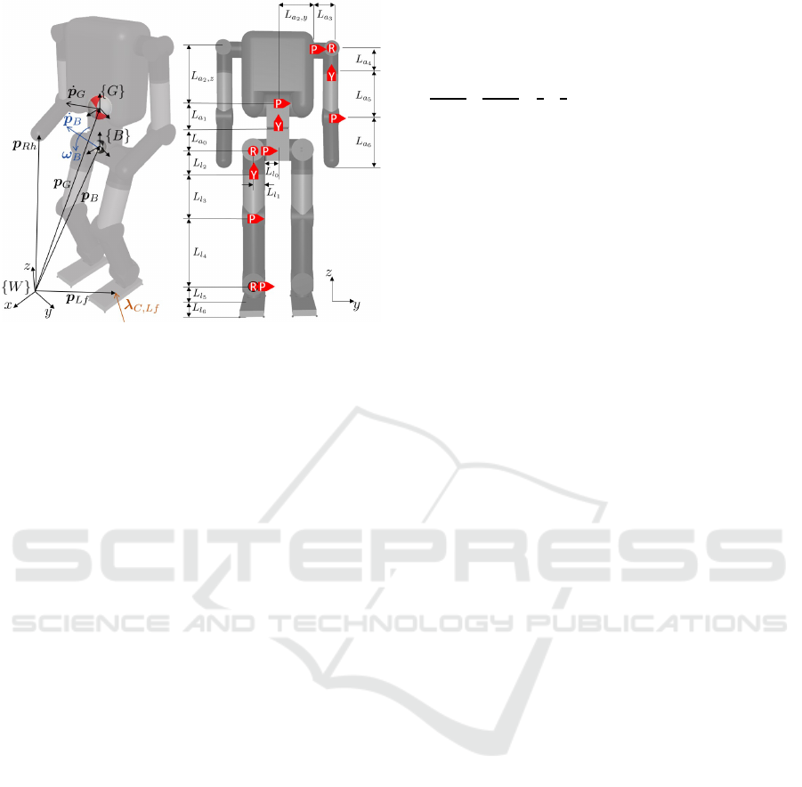
Figure 1: The humanoid model view: {W } notes an world
frame, {B} notes a body frame, {G} notes a frame at the
center of mass.
trol. The difference between methods is investigated
in the situation where unexpected external force en-
ters the system. It is worth to remark that the residual
between desired and unexpected external force does
not disturb the null space motion analytically due to
the characteristic of the inertially decoupled case. In
addition, the simulation result demonstrates the anal-
ysis of each characteristic.
The paper organized as follows. Section 2 de-
scribes the formulation of dynamics with regard to
the extended task space from the joint space with the
floating states. Section 3 describes the three control
methods with the analysis of their characteristics and
differences. Section 4 presents the proper reference
planning and simulation results. Discussions of the
result are also illustrated with some graphs and fig-
ures.
2 DYNAMICS FORMULATION
FOR HUMANOID
The position of the center of mass (CoM) is impor-
tant since it implies the overall momentum and ac-
celeration of the system. Moreover, its characteristic
can ease the complexity of deriving the dynamic for-
mulation of the humanoid robot (Hyon et al., 2007).
Therefore, the proposed generalized coordinates ξ is
ξ =
v
G
˙q
∈ R
n+6
, v
G
=
˙p
G
ω
B
∈ R
6
where ˙p
G
, ω
B
∈ R
3
and ˙q ∈ R
n
are linear velocity of
CoM, angular velocity of the body and joint velocities
as shown in figure 1, respectively.
The equation of motion with regard to ξ generally
forms
M
11
M
12
M
21
M
22
| {z }
M
˙v
G
¨q
|{z }
˙
ξ
+Cξ +
¯m ¯g
0
= §
T
τ
τ + J
T
C
λ
C
(1)
where M ,C ∈ R
(n+6)×(n+6)
are the inertia, Coriolis
& Centrifugal matrices, ¯m is the total mass, ¯g ∈ R
6
is the gravity vector, §
τ
= [0
6
E
n
] ∈ R
n×(n+6)
is the
selection matrix, τ ∈ R
n
is the joint input torque, J
C
∈
R
k×(n+6)
is the constraint Jacobian, and λ
C
∈ R
k
is the
ground reaction force, respectively.
2.1 Task Space Dynamics of Humanoid
Robots
Regarding control using the dynamics represented
by used quantities such as end-effectors in Cartesian
space, the task space coordinates is required. It can
be obtained by the proposed transformation (Henze
et al., 2016) as
˙x = T ξ, T =
E
6
0
Q
T
T
ˆ
J
T
∈ R
(m+6)×(n+6)
(2)
where ˙x =
v
G
˙x
T
∈ R
m+6
is the task space coor-
dinates, ˙x
T
∈ R
m
is the vector of end-effector veloci-
ties, and T is the transformation map, respectively. Q
and
ˆ
J denote the part of Jacobian where the former is
related to v
G
and the latter is related to ˙q as
˙x
T
= Q
T
T
v
G
+
ˆ
J
T
˙q
where Q
T
∈ R
6×m
and
ˆ
J
T
∈ R
m×n
. The general in-
verse of the transformation map is
T
#
=
E
6
0
−
ˆ
J
#
T
Q
T
T
ˆ
J
#
T
(3)
where
ˆ
J
#
T
, W
−1
T
ˆ
J
T
T
(
ˆ
J
T
W
−1
T
ˆ
J
T
T
)
−1
is the gener-
alized inverse of
ˆ
J
T
with the proper weight matrix
W
T
∈ R
n×n
.
By substituting (2) into (1), the equation of motion
for the operational space is derived as
Λ ¨x + Γ ˙x +
¯m ¯g
0
=
"
−Q
T
ˆ
J
#
T
T
ˆ
J
#
T
T
#
τ +
0
˜
λ
C
(4)
with Λ = T
#
T
MT
#
, Γ = T
#
T
(C − M T
#
˙
T )T
#
∈
R
(m+6)×(m+6)
,
˜
λ
C
= §
C
λ
C
∈ R
m
, §
C
∈ R
m×k
.
2.2 Dynamic Equations based on as
Extended Task Space Formulation
The task space dynamics is not sufficient to describe
the entire behavior of the robot since it has a lower
A Comparison Study on Coupling Effects in Balance Control Methods of Humanoid Robots through an Extended Task Space Formulation
207

dimension than the joint space coordinates due to re-
dundancy. Therefore, the consideration of the null
space motion is required to figure out the overall mo-
tion of the robot. The extended task space formula-
tion can visualize the hidden null space dynamics by
parameterizing the minimal null space motion.
The definition of minimal null space motion ˙x
N
∈
R
r
is proposed (Oh et al., 1997) (Oh and Chung,
1999) as follows
˙x
N
, (V
T
W
N
V )
−1
V
T
W
N
| {z }
J
N
ξ =
Q
T
N
ˆ
J
N
ξ (5)
with the general solution of (2)
ξ = T
#
˙x +(E
n+6
− T
#
T )ξ = T
#
˙x +V ˙x
N
(6)
where J
N
∈ R
r×(n+6)
and V = [0
ˆ
V
T
]
T
∈ R
(n+6)×r
denote the Jacobian and the basis matrix of minimal
null space, Q
N
∈ R
6×r
,
ˆ
J
N
∈ R
r×n
, r = n − m with
the proper weighting matrix W
N
∈ R
(n+6)×(n+6)
, re-
spectively.
The extended task space ˙x
E
=
v
G
˙x
T
˙x
N
∈
R
n+6
is defined as follows.
˙x
E
= T
E
ξ, T
E
=
E
6
0
Q
T
T
ˆ
J
T
Q
T
N
ˆ
J
N
∈ R
(n+6)×(n+6)
(7)
where T
E
is the extended transformation map. The
general inverse of this map is
T
−1
E
=
E
6
0 0
−
ˆ
J
#
T
Q
T
T
−
ˆ
J
#
N
Q
T
N
ˆ
J
#
T
ˆ
J
#
N
(8)
where
ˆ
J
#
N
=
ˆ
V ∈ R
n×r
.
By substituting (7) into (1), the equation of motion
for an extended task space is derived as
Λ
E
¨x
E
+ Γ
E
˙x
E
+
¯m ¯g
0
0
=
−Q
T
ˆ
J
#
T
T
− Q
N
ˆ
J
#
T
N
ˆ
J
#
T
T
ˆ
J
#
T
N
τ +
0
˜
λ
C
0
(9)
where Λ
E
= T
−T
E
MT
−1
E
, Γ
E
= T
−T
E
(C −
MT
−1
E
˙
T
E
)T
−1
E
∈ R
(n+6)×(n+6)
. In addition, the
relation between Λ
E
, Γ
E
and Λ, Γ can be visualized
from the following equations.
Λ
E
=
Λ
G
Λ
T
Λ
N
=
˜
Λ
G
Λ
GN
˜
Λ
T
Λ
T N
˜
Λ
N
Λ
NN
=
Λ
˜
Λ
T
N
˜
Λ
N
Λ
NN
(10)
Γ
E
=
Γ
G
Γ
T
Γ
N
=
˜
Γ
G
Γ
GN
˜
Γ
T
Γ
T N
˜
Γ
N
Γ
NN
=
Γ
˜
Γ
T
N
˜
Γ
N
Γ
NN
(11)
where Λ
NN
, Γ
NN
,
˜
Λ
N
,
˜
Γ
N
denote the hidden null
space dynamics. As shown in (10) and (11),
˜
Λ
N
,
˜
Γ
N
makes coupling effect between the task space and
the null space motion because it is not zero. In this
sense, the null space motion could interfere with the
task space motion if there is not considerations on the
coupling effect.
3 BALANCE CONTROLLER
DERIVATION FOR HUMANOID
In this section, the controllers based on the computed
torque method are developed through the proposed
formulation with the quadratic programming.
The closed-loop behavior candidate based on the
computed torque method is
Λ
E
( ¨e
E
+ K
D,E
˙e
E
+ K
P,E
e
E
) =
0
˜
λ
opt
C
0
−
0
˜
λ
C
0
(12)
where e
E
= x
E,d
− x
E
is the error of the extended
tasks. To achieve (12) , the input joint torque forms as
follows.
τ =
ˆ
J
T
ˆ
J
N
T
Λ
T
Λ
N
¨x
re f
E
+
Γ
T
Γ
N
˙x
E
−
˜
λ
opt
C
0
(13)
with
¨x
re f
E
, ¨x
E,d
+ K
D,E
˙e
E
+ K
P,E
e
E
(14)
˜
λ
opt
C
= argmin
δ
T
G
W
G
δ
G
+
˜
λ
opt
T
C
W
C
˜
λ
opt
C
(15)
and
δ
G
,
¯
Λ
E
¨x
re f
E
+
¯
Γ
E
˙x
E
+ ¯m ¯g − Q
T
˜
λ
opt
C
¯
Λ
E
= Λ
G
+ Q
T
Λ
T
+ Q
N
Λ
N
¯
Γ
E
= Γ
G
+ Q
T
Γ
T
+ Q
N
Γ
N
where K
P,E
and K
D.E
denote the stiffness and damp-
ing matrices, W
G
and W
C
are positive definite
weighting matrices, respectively. The quadratic pro-
gramming in (15) is conducted based on the proper
equality and inequality constraints as follows.
p
CoP
∈ A
CoP
f
i,x
≤ µ
x
f
i,z
f
i,y
≤ µ
y
f
i,z
The p
CoP
and the A
CoP
denote the position of center
of pressure(CoP) and the area where it should be, and
f
i
= ( f
i,x
f
i,y
f
i,z
), i = 1, ··· ,4 is an external force for
each foot as shown in figure 2.
For the ideal case, with the assumptions that δ
C
,
˜
λ
opt
C
−
˜
λ
C
→ 0 and δ
G
→ 0, the (12) shows exponen-
tially convergence property since
¨e
E
+ K
D,E
˙e
E
+ K
P,E
e
E
= 0. (16)
ICINCO 2019 - 16th International Conference on Informatics in Control, Automation and Robotics
208

Figure 2: The linear and angular force at each foot based on
the ground reaction forces from 4 point contacts.
3.1 Comparison between Kinematically
Decomposed Control and Inertially
Decoupled Control
It is called the kinematically decomposed con-
trol(KDC) for the case that W
T
, W
N
are identity ma-
trices. Then, there are coupling effect as shown in the
following original closed-loop behavior
Λ
˜
Λ
T
N
˜
Λ
N
Λ
NN
¨e + K
D
˙e + K
P
e
¨e
N
+ K
D,N
˙e
N
+ K
I,N
R
˙e
N
dt
=
δ
0
(17)
where ˙e = ˙x
d
− ˙x, ˙e
N
= ˙x
N,d
− ˙x
N
denote the part of
error ˙e
E
and K
P
, K
D
, K
D.N
, K
I,N
are proper gains
corresponding with K
P,E
, K
D,E
, respectively. The
residual δ , (δ
G
δ
C
) ∈ R
m+6
is not generally zero
since the ground reaction force
˜
λ
C
is the external en-
vironmental parameter. For instance, the impulsive
force could occur when a foot lands or collides with
an object. It is quite difficult to obtain the precise
˜
λ
opt
C
satisfying δ
C
= 0 at an instance. Therefore, due to the
coupling effect, the residual could impede conserva-
tion on the null space motion and subsequent unstable
null space dynamics could affect the task space mo-
tion.
On the other hand, the inertia matrix (10) can be
decoupled between the task space and the null space
since
˜
Λ
N
= 0 by selecting proper weighting matrices
W
T
= M
22
and W
N
= M. It is called the inertially
decoupled control(IDC) and its closed-loop behavior
forms as following
Λ( ¨e + K
D
˙e + K
P
e) = δ (18)
¨e
N
+ K
D,N
˙e
N
+ K
I,N
Z
˙e
N
dt = 0 (19)
As shown in (18) and (19), the closed-loop system
of null space is completely decoupled with the task
space and the δ only affect to the task space motion.
It is worthwhile that the null space motion does not
affect the task space completely on the inertially de-
couple controller.
3.2 Reformulation of Conventional
Operational Space based Control in
Terms of Inertially Decoupled
Control
The operational space dynamics (4) derives the joint
input torque similar with (13) as follows.
τ =
ˆ
J
T
T
˜
Λ
T
¨x
re f
+
˜
Γ
T
˙x −
˜
λ
opt
C
+ P
T
N
τ
q
(20)
with
¨x
re f
, ¨x
d
+ K
D
˙e + K
P
e (21)
τ
q
= K
N
(q
d
− q) − D
N
˙q (22)
where
δ
G
,
¯
Λ ¨x
re f
+
¯
Γ ˙x + ¯m ¯g − Q
T
˜
λ
C
¯
Λ =
˜
Λ
G
+ Q
T
˜
Λ
T
¯
Γ =
˜
Γ
G
+ Q
T
˜
Γ
T
where P
N
= E
n
−
ˆ
J
#
T
ˆ
J
T
is the null projection matrix
with W
T
= M
22
. It is called the operational space
control(OSC) since it focuses on the task space with
the conventional null space control by P
T
N
τ
q
. Accord-
ing to (6) and (8),
P
N
=
ˆ
V
ˆ
J
N
(23)
since T
−1
E
T
E
= T
#
T + V J
N
= E
n+6
. By substitut-
ing τ as an input into (9), the closed loop behavior is
derived as follows.
Λ( ¨e + K
D
˙e + K
P
e) = δ −
˜
Γ
T
N
˙x
N
(24)
Λ
NN
¨x
N
+ Γ
NN
˙x
N
+
˜
Γ
N
˙x =
ˆ
V
T
τ
q
(25)
Although it is already inertially decoupled since
˜
Λ
N
= 0 with assumption δ → 0, the coupling effect
˜
Γ
T
N
˙x
N
enters to the task space dynamics as (24). The
torque for null motion can be expressed with regard
to the desired null space motion defined as following
˙x
N,d
, J
N
M
−1
OU(q) (26)
with the potential U(q) =
∑
n
i
1
2
η
i
(q
i,d
− q
i
). In addi-
tion, K
N
= κE
n
, K
N,D
= κE
r
and K
D
= κM
22
with
the scalar gain κ as (Oh et al., 1998). The equivalent
null space torque with respect to (13) is
P
T
N
τ
q
= κ
ˆ
J
T
N
Λ
NN
˙e
N
(27)
Therefore, it gives the same effect at setting ¨x
N,d
= 0,
K
I,N
= 0 and excluding the compensating term
˜
Γ
N
˙x.
In other words, the above equation shows that the con-
trol input through (27) has some limitation for the pre-
cise tracking performance on the null space. In this
sense, It is expected that the error ˙e
N
would not show
convergence with the input (20) since the closed-loop
behavior on the null space (25) cannot be expressed
as an error dynamics form.
A Comparison Study on Coupling Effects in Balance Control Methods of Humanoid Robots through an Extended Task Space Formulation
209

Figure 3: Simulation model (MuJoCo).
Table 1: Simulation Model Parameters.
Parameter Length(m) Mass(kg) Inertia(10
−4
kg · m)
L
l
0
L
a
0
0.05
0.1
5 diag(135.0, 135.0, 83.00)
L
l
1
0.06 0.5 diag(4.625, 6.250, 4.625)
L
l
2
0.1 0.5 diag(7.292, 7.292, 6.250)
L
l
3
0.2 1.5 diag(59.00, 19.00, 59.00)
L
l
4
0.3 1.5 diag(19.00, 122.0, 122.0)
L
l
5
0.07 0.25 diag(3.125, 2.583, 2.583)
L
l
6
0.03 0.75 diag(45.00, 6.813, 40.00)
L
a
1
0.1 5 diag(83.00, 83.00, 83.00)
L
a
2
,z
L
a
2
,y
0.25
0.16
15 diag(1450., 2405., 1250.)
L
a
3
0.08 0.5 diag(3.792, 2.250, 3.792)
L
a
4
0.1 0.5 diag(5.292, 5.292, 2.250)
L
a
5
0.2 1.0 diag(36.00, 4.500, 36.00)
L
a
6
0.2 1.0 diag(4.500, 36.00, 36.00)
4 EVALUATION OF SIMULATION
RESULTS
The simulation was developed with the proposed con-
troller based on the humanoid model as shown in fig-
ure 3. Its specific parameters are depicted in figure 1
and Table 1 such as a mass, inertia and length of each
link. Its height and total mass are designed to be 1.2m
and 41kg. It has 28 degrees of freedom (DoF) with 22
joints in which each leg has 6 and each arm has 4 and
a spine has 2 joints. Each dimension of the space is
n = 22, m = 18, r = 4, k =
6 (Single support)
12 (Double support)
The position, orientation, linear and angular velocities
at the body frame (p
B
,R
B
, ˙p
B
,ω
B
) are considered as
known values by the suitable IMU sensor and the es-
timator. The simulation was performed by use of a
commercial software MuJoCo (Todorov et al., 2012)
with Win 32 compiler.
Because the extended task space formulation (9)
requires heavy computation due (Prete et al., 2015) to
M
−1
,
d
dt
(M
−1
) and M
12
6= 0, it needs a substantial
time interval for real-time control. However, the fol-
Figure 4: ZMP/CoM trajectory of frontal plane. The z
L f ,d
and z
R f ,d
denotes the desired z directional motion of each
foot for marching in place. T
S
= 0.1s and T
D
= 0.4s are
time intervals for single and double supported cases, respec-
tively.
lowing input form is exactly equivalent with (13) and
demands relatively light computation.
τ = §
T
τ
M
˙
ξ
re f
+ Cξ − T
T
E
0
˜
λ
opt
0
(28)
with
˙
ξ
re f
= T
−1
E
( ¨x
re f
E
−
˙
T
E
ξ) (29)
With the input form (28), the simulation is conducted
with 1Khz of solving rate and 500hz of control rate.
4.1 Reference Planning for the Motion
of Marching in Place
To figure out the effect of δ
C
, the task space refer-
ence is designed for marching in place. The motion
for center of mass on the frontal plane is obtained by
solving the equation of inverted pendulum as follows.
¨p
G,y
= ω
2
(p
G,y
− y
zmp
), ω
2
=
g
h
z
(30)
where h
z
is height of CoM from the ground, g =
9.81m/s
2
is the gravity acceleration and y
zmp
denotes
zero moment point (ZMP), respectively. According
to the above differential equation, the reference ZMP
and CoM trajectories in figure 4 is achieved (Oh et al.,
2006).
Each foot is raised up and down in the single sup-
port duration while the other end-effector and CoM
motions are fixed with regard to the world frame.
The desired null space motion ˙x
N,d
is designed as
(26) where q
i,d
= 0 and η
i
= 0 for all i except η
13
=
η
14
= η
16
= η
20
= 1.
4.2 Evaluation of the Results
In this section, it shows the task space performance
and the null space motion through the simulation re-
sults. To exaggerate the coupling effect due to the
ICINCO 2019 - 16th International Conference on Informatics in Control, Automation and Robotics
210

(a) Null space motion 1 (b) Null space motion 2
(c) Null space motion 3 (d) Null space motion 4
Figure 5: Null space motion on the kinematically decom-
posed control. Blue and red lines denote the desired and the
present null space motion, respectively.
(a) Null space motion 1 (b) Null space motion 2
(c) Null space motion 3 (d) Null space motion 4
Figure 6: Null space motion on the inertially decoupled
control. Blue and red lines denote the desired and the
present null space motion, respectively.
residual δ
C
, each foot collides with the ground at
−0.5m/s during the marching motion as shown in fig-
ure 3 and figure 4. Because the
˜
λ
opt
C
in (15) is han-
dled as feedforward, the residual exists generally and
it would be especially emphasized at colliding with
other objects such as the ground in landing motion.
Figure 5 and figure 6 present the null space mo-
tion of the KDC and IDC, respectively. The null space
tasks ˙x
N
does not have any units since it is indepen-
dent with the Cartesian space tasks and does not have
physical meaning. In KDC, the force residual δ
C
af-
fect the null space motion as its closed loop behavior
(17), which is shown in figure 5.
In contrast, the IDC method does not transfer its
effect to the null space motion analytically as the
closed loop behavior (18) and (19). The simulation
result demonstrates that the motion of null space tasks
(a) Null space motion 1 (b) Null space motion 2
(c) Null space motion 3 (d) Null space motion 4
Figure 7: Null space motion on the operational space con-
trol. Blue and red lines denote the desired and the present
null space motion, respectively.
is almost unaffected by the residual δ
C
with respect
to the kinematically decomposed case at landing each
foot.
The figure 7 shows the null space motion on OSC.
Because it does not contain the desired acceleration,
integrator and compensator for the null space as (27),
it is expected that there is some limitation for the
tracking performance. The simulation result presents
that the null space motion does not show damping re-
sponse and convergence of the steady error. In addi-
tion, even though it is also one of the inertially de-
coupled cases due to
˜
Λ
N
= 0, the larger effect of the
residual δ
C
is shown compared to figure 6. It could
be explained because it does not compensate for the
coupling effect
˜
Γ
N
˙x.
Figure 8 shows the position error of CoM and it
describes the tracking performance on the task space
with the given reference. The CoM motions followed
well for all controllers, but the magnitude of the error
is smallest for IDC and largest for OSC. It gives an
example that the task space motion is, although small,
impeded by the inertially coupling effect through
˜
Λ
N
on KDC and the uncompensated dynamic coupling
effect
˜
Γ
T
N
˙x
N
on OSC. Therefore, there is a possibil-
ity that the more vigorous motion there is in the null
space, the more coupling effect that disturbs the task
space motion at using KDC or OSC.
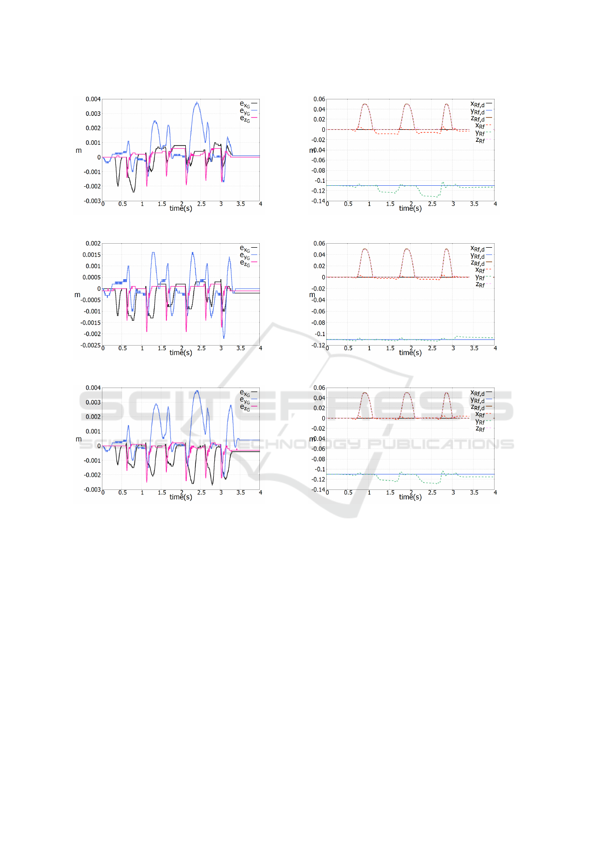
Most interesting results in this simulation are sug-
gested by the motion of each foot figure 9. With re-
gard to the marching motion, each foot does not have
x and y directional motion, albeit it moves up and
down to the z-axis. Therefore, the existence of error
when the z-axis reference is zero indicates an exam-
ple of a slip for each foot. A comparison of figure 9a,
figure 9b and figure 9c shows that the smallest slip
appears in the IDC. It suggests that the inertially cou-
A Comparison Study on Coupling Effects in Balance Control Methods of Humanoid Robots through an Extended Task Space Formulation
211
(a) The error of CoM on KDC
(b) The error of CoM on IDC
(c) The error of CoM on OSC
Figure 8: Errors of the CoM on the each controller.
pling effect at KDC and the uncompensated coupling
effect at OSC have an influence on the landing situa-
tion, and the inertially decoupling process of IDC has
a positive effect for such a situation.
5 CONCLUSION
In this paper, it present three whole-body controllers
for the balance of humanoids by using an extended
task space formulation. The dynamic coupling effects
are manifested since the extended task space form can
represent the entire system dynamics. Through the
decoupling process by selecting the weighting matri-
ces carefully, the effects are inertially decoupled be-
(a) The motion of the right foot on KDC
(b) The motion of the right foot on IDC
(c) The motion of the right foot on OSC
Figure 9: Motion of the right foot on the each controller.
tween each space. On the comparison study, we com-
pare cases of the controller with or without the decou-
pling process mathematically to confirm the impact
of coupling effects. Moreover, the conventional op-
erational space based control is also analyzed in the
absence of any compensator for showing the conver-
gence of the errors in the closed-loop behavior.
The simulation model has 28 degrees of freedom
with 22 joints. The robot conducts marching mo-
tion to generate the unexpected ground reaction force
while the other position of CoM and end-effectors are
fixed. The simulation result shows the coupling ef-
fect between task space and null space. The inertially
decoupled control method reduces its effect conspic-
uously. In addition, the simulation results back up the
ICINCO 2019 - 16th International Conference on Informatics in Control, Automation and Robotics
212

analysis that tracking performance of the null space
motion would not be precise on the conventional op-
erational space based control due to the lacking in
compensator. Therefore, while it is the simplest con-
ventional one, the results indicate the importance of
consideration for the null space dynamics.
REFERENCES
Henze, B., Roa, M. A., and Ott, C. (2016). Passivity-
based whole-body balancing for torque-controlled hu-
manoid robots in multi-contact scenarios. Intl. Journal
of Robotics Research.
Herzog, A., Rotella, N., Mason, S., Grimminger, F., Schaal,
S., and Righetti, L. (2016). Momentum control with
hierarchical inverse dynamics on a torque-controlled
humanoid. Autonomous Robots.
Hyon, S.-H., Hale, J. G., and Cheng, G. (2007). Full-body
compliant human-humanoid interaction: Balancing in
the presence of unknown external forces. IEEE Trans-
actions on Robotics.
Kim, J. H., moon Hur, S., and Oh, Y. (2018a). l
1
robust-
ness of computed torque method for robot manipula-
tors. IEEE Intl. Conf. on Robotics and Automation.
Kim, J. H., moon Hur, S., and Oh, Y. (2018b). A study
on the l
∞
/l
2
performance of a computed torque con-
troller. IEEE Intl. Conf. on Industrial Technology.
Koolen, T., Bertrand, S., Thomas, G., De Boer, T., Wu, T.,
Smith, J., Englsberger, J., and Pratt, J. (2016). Design
of a momentum-based control framework and applica-
tion to the humanoid robot atlas. International Journal
of Humanoid Robotics.
Mistry, M., Nakanishi, J., Cheng, G., and Schaal, S. (2008).
Inverse kinematics with floating base and constraints
for full body humanoid robot control. IEEE-RAS Intl.
Conf. on Humanoid Robots.
Nakanishi, J., Mistry, M., and Schaal, S. (2007). Inverse
dynamics control with floating base and constraints.
IEEE Intl. Conf. on Robotics and Automation.
Oh, Y. and Chung, W.-K. (1999). Disturbance-observer-
based motion control of redundant manipulators using
inertially decoupled dynamics. IEEE/ASME Transac-
tion on Mechatronics.
Oh, Y., Chung, W.-K., and Youm, Y. (1997). Extended
impedance control of redundant manipulators using
joint space decomposition. IEEE Intl. Conf. on
Robotics and Automation.
Oh, Y., Chung, W.-K., and Youm, Y. (1998). Extended
impedance control of redundant manipulators based
on weighted decomposition of joint space. Journal of
Robotic Systems.
Oh, Y., ho Ahn, K., Kim, D., and Kim, C. (2006). An
analytical method to generate walking pattern of hu-
manoid robot. Annual Conference of the IEEE Indus-
trial Electronics Society.
Ott, C., Albu-Schaffer, A., Kugi, A., and Hirzinger, G.
(2008). On the passivity-based impedance control of
flexible joint robots. IEEE Transactions on Robotics.
Ott, C., Roa, M. A., and Hirzinger, G. (2011). Posture
and balance control for biped robots based on con-
tact force optimization. IEEE-RAS Intl. Conf. on Hu-
manoid Robots.
Prete, A. D., Nori, F., Metta, G., and Natale, L. (2015).
Prioritized motion–force control of constrained fully-
actuated robots: “task space inverse dynamics”.
Robotics and Autonomous Systems.
Sentis, L. and Khatib, O. (2005). Control of free-floating
humanoid robots through task prioritization. IEEE
Intl. Conf. on Robotics and Automation.
Sentis, L. and Park, J. (2004). Whole-body dynamic behav-
ior and control of human-like robots. Intl. Journal of
Humanoid Robotics.
Stephens, B. J. and Atkeson, C. G. (2010). Dynamic bal-
ance force control for compliant humanoid robots.
IEEE/RSJ Intl. Conf. on Intelligent Robots and Sys-
tems.
Todorov, E., Erez, T., and Tassa, Y. (2012). Mujoco: A
physics engine for model-based control. IEEE Intl.
Conf. on Robotics and Systems.
A Comparison Study on Coupling Effects in Balance Control Methods of Humanoid Robots through an Extended Task Space Formulation
213
