
Design of a Circular-type Pod Silencer
for a High-pressure Axial Flow Fan
Hyun Gwon Kil
1
, Chan Lee
1
, Jong Jin Park
1
and Sang Moon Yang
2
1
Department of Mechanical Engineering, University of Suwon, Hwaseong-si, Gyeonggi-do, Republic of Korea
2
Samwon E&B, Siheung-si, Gyeongg-doi, Republic of Korea
Keywords: Circular-type Pod Silencer, Axial Flow Fan, Transmission Loss.
Abstract: A circular-type pod silencer has been designed to reduce a high noise level generated from an axial flow
fan. The noise consists of two components such as discrete frequency noise component at blade passing
frequency due to rotating impellers and broadband noise component due to turbulence produced in the axial
fan. Main contribution into the high noise level is due to the discrete frequency noise component. In order to
effectively reduce the noise level of the axial flow fan, the circular-type pod silencer has been modelled in
this paper. In order to identify critical design parameters, finite element analysis (FEA) with commercial
ANSYS acoustic code was implemented. The results of the design parametric study have been used to
design the circular-type pod silencer that effectively reduces the high noise level of the axial flow fan in
subway ventilation system.
1 INTRODUCTION
Axial flow fans are widely used in low pressure air
handling systems such as cooling, air-conditioning,
or ventilating equipment (Dixon, 2014). But subway
ventilation systems require axial flow fans with
relatively high pressure at high flow capacity. Those
generate high noise level. The noise consists of two
components such as discrete frequency noise
component at blade passing frequency (BPF) due to
rotating impellers and broadband noise component
due to turbulence in inflow and exhaust jet mixing
(Lee and Kil, 2018). Main contribution into the high
noise level is due to the discrete frequency noise
component. It is needed to attach silencers to reduce
the high noise level. Rectangular silencers in subway
ventilation systems have been widely used. But
those silencers generate relatively high pressure loss.
Therefore, there have been industrial needs for
reducing high noise level with circular-type pod
silencers effective to axial flow fan performance
with lower pressure loss.
The circular-type pod silencer was analyzed by
using transfer matrix method with plane wave
approximation (Munjal, 2003). Multimode sound
propagation was used to analyze the circular-type
pod silencer (Kirby, 2006). FEA approach was
implemented to analyze dissipative silencers (Peat
and Rathi, 1995; Mehdizadeh and Paraschivoiu,
2005; Cui et al., 2014). The design curves for
performance evaluation of passive pod silencers
were provided by simulating the acoustic
performance of the silencers with commercial FEA
software (Ramarkrishnan, 2015). Practical design of
the circular-type pod silencer have been widely
performed experimentally or based on existing
experimental results and design curves in reference
(Ver and Beranek, 2006). In this paper, in order to
reduce the high noise level of an axial flow fan in a
subway ventilation system, design of the circular-
type pod silencer has been performed with FEA
simulation using commercial ANSYS acoustic code
(ANSYS, 2019). The transmission loss of the
silencer was evaluated by solving the three-
dimensional sound wave equation inside the silencer.
The design parametric study has been performed to
identify critical design parameters. It has been
implemented to design the circular-type pod
silencer that
effectively reduces the high noise level
of the axial flow fan in the subway ventilation
system.
Kil, H., Lee, C., Park, J. and Yang, S.
Design of a Circular-type Pod Silencer for a High-pressure Axial Flow Fan.
DOI: 10.5220/0007838402630268
In Proceedings of the 9th International Conference on Simulation and Modeling Methodologies, Technologies and Applications (SIMULTECH 2019), pages 263-268
ISBN: 978-989-758-381-0
Copyright
c
2019 by SCITEPRESS – Science and Technology Publications, Lda. All rights reserved
263

2 THEORY
2.1 Sound Transmission Loss and
Insertion Loss
In order to reduce the noise generated from the axial
flow fan, a silencer is attached to the fan. The noise
attenuation performance of the silencer is evaluated
in terms of transmission loss (TL) and insertion loss
(IL).
TL is defined as the logarithmic ratio between
the incident sound power
at the inlet of the
muffler and the transmitted sound power
at the
outlet of the silencer in Figure 1 as
(1)
Figure 1: Layout for evaluation of transmission loss.
If the area of the inlet is the same as the area of the
outlet, TL can be experessed with complex
amplitude of the incident pressure
and complex
amplitude of transmitted pressue
as
(2)
Figure 2: Layout for evaluation of insertion loss.
IL is defined as the difference between sound
power level Lp
2
at the termination without the
silencer and sound power level Lp
1
at the
termination with the silencer installed as shown in
Figure 2. In the case of IL, it is not necessary to
install an anti-reflection terminal as shown in Figure
2. Thus it is closer to an actual value of noise
attenuation because all actually installed connectors
related to the fan and the silencer are considered.
If the cross-sectional area of the inlet is equal to
the cross-sectional area of the outlet and the outlet is
anti-reflected, TL and IL become equal. Assuming
this condition, TL has been considered to design the
silencer in this paper.
2.2 Finite Element Analysis
Numerical simulation methods play an increasingly
important role in the design of silencers as well as
other noise and vibration applications. FEA offers an
advantageous combination of modelling flexibility,
computational efficiency and result accuracy.
Comparing to the boundary element analysis (BEA),
FEA allows modelling more complex physics of
acoustics considering multiple fluid domains, sound
propagation in a mean flow and effects of
temperature gradients in a fluid medium. FEA can
be especially used to design of the silencers to
reduce relatively high frequency noise considering
the higher modes above the cut-off frequency for the
plane wave approximation as well as to design the
silencers with relatively complex shapes.
(a) (b)
Figure 3: (a) Structural shape and (b) finite element model
of an circular-type pod silencer.
The linear wave equation for perfect gas with no
damping is expressed in terms of pressure and
speed of sound as
(3)
At each frequency in the interested frequency range
that equation (3) becomes Helmholz’s equation as
(4)
where P, mean complex pressure amplitude and
the acoustic wavenumber at the given frequency,
respectively. The three dimensional acoustic domain
of the silencer in Figure 3(a) is divided into elements
in Figure 3(b). The variational formulation of the
silencer problem allows to formulate the discretized
equation of linear systems of algebraic equations as
(5)
SIMULTECH 2019 - 9th International Conference on Simulation and Modeling Methodologies, Technologies and Applications
264
where
and are the coefficient matrix,
sound pressure amplitude vector of nodal values and
forcing function vector of nodal values, respectively.
In the present silencer problem, is only a non-
zero value at the inlet pipe according to Dirichlet
boundary condition with unit pressure.
In this study, FEA is performed with a
commercial FEA program ANSYS. For more
efficient way to model perforation of the silencer,
meshes on the perforated tube are replaced by the
two inner and outer concentric surfaces with
acoustic transfer admittance. For the acoustic
transfer admittance, the transfer admittance of the
perforated plate (Mechel, 2008) with the same
perforation pattern of the perforation tube is used.
Another effective method is to use equivalent fluid
model to model sound absorbing materials in the
silencer. In this work Miki equivalent fluid model
(Miki, 1990) has been implemented, that uses the
following expressions for the complex
characteristics impedance
and complex
wavenumber of the sound absorbing material at
frequency as
(6)
(7)
Here
and correspond to air density, speed of
sound and fluid resistivity of the sound absorbing
material, respectively. It is known that Miki
equivalent fluid model is regarded valid in the
frequency range of < 0.01. .
3 ANALYSIS
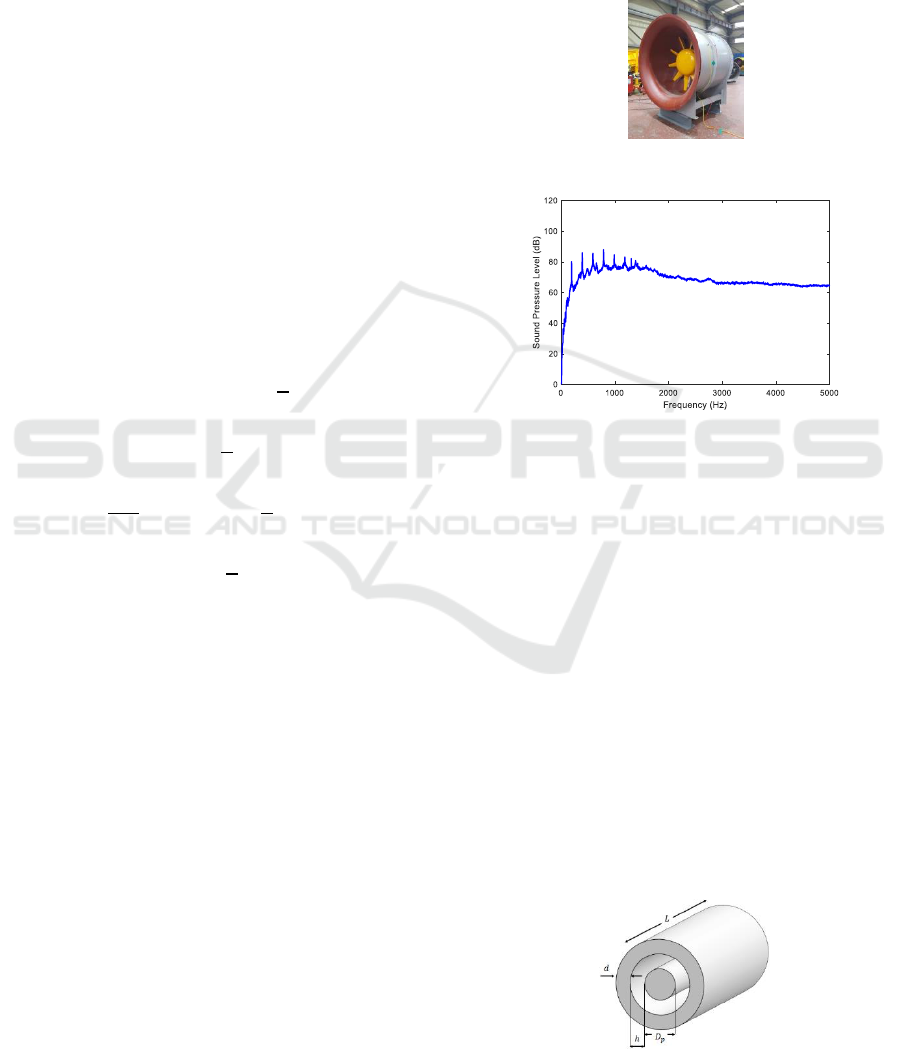
3.1 Noise Characteristics Analysis
The noise source considered in this research is an
axial flow fan (Figure 4) operating with high
pressure rise at high flow capacity in the subway
ventilation system. It generates high noise level. The
noise consists two kinds of noise components such
as discrete frequency noise at BPF and the
broadband noise distributed over wide frequency
range. BPF noise is produced mainly due to rotating
steady fan blade thrust and blade interaction.
Broadband noise is produced over entire frequency
range due to turbulent boundary layer on blade
surface, inflow turbulence and blade wake. Figure 5
shows the typical pattern of noise spectrum
measured from the regenerative blower. Here BPF
corresponds to 198 Hz.
Figure 4: Axial flow fan.
Figure 5: Measured noise spectrum of axail flow fan.
3.2 Verification of Analysis
In order to verify the FEA simulation approach, FEA
has been applied to evaluate TL of silencer models
in reference (Beranek, 2006). The silencer models
are circular-type silencer without a pod, circular-
type silencer with a rigid pod and circular-type
silencer with sound absorbing pod (
. Those have dimensions as
and as
shown in Figure 6.
The predicted numerical results for TL have been
compared with the corresponding results in the
reference (Beranek, 2006) as shown in Figure 7. It
showed that FEA approach can be used to evaluate
TL of the circular-type pod silencers in good
agreement with the experiment results in the
reference.
Figure 6: Silencer models for analysis verification.
Design of a Circular-type Pod Silencer for a High-pressure Axial Flow Fan
265

Figure 7: Comparison of the predicted TL of silencers
(without a pod [model A], with a rigid pod [model B] and
with an sound absorbing pod [model C], respectively) with
results in the reference.
3.3 Tl Characteristics
The design model is the circular-type pod silencer as
shown in Figure 8. The outer surface of the sound
absorbing pod and the inner surface of the outer
sound absorbing layer are formed of perforated tubes.
The design variables are outer diameter
, inner
diameter
, sound absorbing pod diameter
, air
flow gap thickness , sound absorbing outer layer
thickness , type of sound absorbing material,
density of sound absorbing material and porosity
of perforated tubes. Considering a flame retarding
material, glass wool is selected as the type of the
sound absorbing material.
Figure 8: Design model of the circular-type pod silencer.
The design parametric study was performed by
evaluating TL. Figures 9-11 show the influence of
changing corresponding design variable on TL of the
silencer. Figure 9(a) shows little influence of
changing the thickness of the absorbing outer layer
on TL if it is more than about 0.2 m. Figure 9(b)
shows that the air flow gap thickness decreases, TL
increases in all frequency region and the frequency
at which the maximum TL value occurs also
increases.
Figure 10(a) shows that the length of the silencer
increases, the TL value increases in the main noise
reduction frequency band. Figure 10(b) shows that
the pod diameter increases, TL also increases in the
main noise reduction frequency band.
Figure 9: Influence of corresponding design variable
change on TL of the silencer as (a) outer sound absorbing
layer thickness, (b) air flow gap thickness.
Figure 10: Influence of corresponding design variable
change on TL of the silencer as (a) silencer length and (b)
sound absorbing pod diameter.
Figure 11(a) shows that the density of the sound
absorbing material increases, the main noise
reduction frequency band increases but the
maximum TL value decreases. Figure 11(b) shows
little influence of changing the porosity of the
perforated tube on TL, if it is more than about
46.2 %. The parametric study results show that the
most sensitive design parameter corresponds to the
air flow gap thickness.
SIMULTECH 2019 - 9th International Conference on Simulation and Modeling Methodologies, Technologies and Applications
266
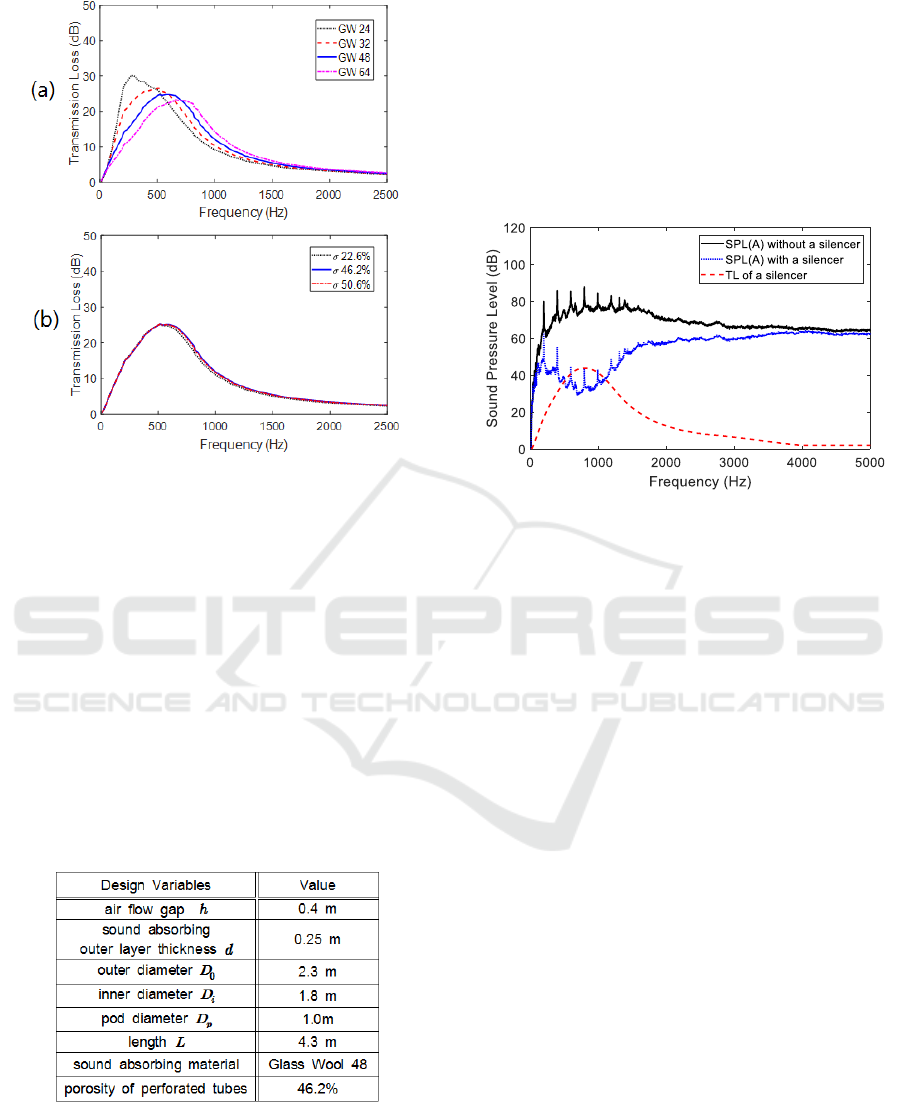
Figure 11: Influence of corresponding design variable
change on TL of the silencer as (a) sound absorbing
material density in unit of
and (b) porosity of the
perforated tubes.
4 RESULTS
In order to design the circular-type pod silencer, the
silencer installation space condition in subway
provides constraints as
and
Considering the fan casing inner diameter of
the axial flow fan, constraint as
is also
given.
Table 1: Specifications of the designed circular-type pod
silencer.
Considering the parametric study results and the
design constraints, the specifications of the circular-
type pod silencer have been determined as design
variables in Table 1. When the designed silencer is
attached to the axial flow fan, the reduced noise
reduction can be evaluated as follows. First, TL of
the designed silencer is evaluated over the frequency
range between 0 and 5 kHz as shown in Figure 12.
Second the reduced noise SPL spectrum is obtained
by subtracting TL from the measured noise spectrum
of the axial flow fan itself as shown in Figure 12.
The overall SPL of 106 dB(A) is expected to be
reduced to 94 dB(A) by attaching the circular-type
pod silencer.
Figure 12: Reduced noise spectrum of the axial fan with
the silencer, that is evaluated by subtracting TL from the
measured noise spectrum of the axial fan, itself.
5 CONCLUSIONS
A circular-type pod silencer has been designed to
reduce a high noise level that is generated from the
axial flow fan in subway. In order to effectively
reduce the noise, the design parametric study has
been performed using FEA. It has been implemented
to design the circular-type pod silencer that
effectively reduces the high noise level generated
from the axial flow fan. The overall SPL of
106dB(A) has been expected to be reduced to 94
dB(A). In order to get more noise reduction, a
circular-type pod silencer with annular two layers
can be considered. Further research is expected to
design the circular-type pod silencer with annular
two layers.
ACKNOWLEDGEMENTS
This work was supported by the Korea Institute of
Energy Technology Evaluation and Planning
(KETEP) and the Ministry of Trade, Industry &
Energy (MOTIE) of the Republic of Korea
(
20172010106010
).
Design of a Circular-type Pod Silencer for a High-pressure Axial Flow Fan
267

REFERENCES
Dixon, S.L., 2014. Fluid mechanics and thermodynamics
of Turbomachinery, Butterworth & Heinemann, 7
th
edition.
Lee, C., Kil, H.G., 2018. A new through-flow analysis
method of axial flow fan with noise models, Euronoise.
Munjal, M.L., 2003. Analysis and design of pod silencers,
Journal of Sound and Vibration, 262(3).
Kirby, R., 2006. Multi-mode sound propagation in pod
silencers, 13
th
International Congress on Sound and
Vibration.
Peat, K.S., Rathi, K.L., 1995. A finite element analysis of
the convected axcostic wave motion in dissipative
silencers, Journal of Sound and Vibration, 184(3).
Mehdizadeh, O.Z., Paraschivoiu, 2005. A three-
dimensional finite element approach for predicting the
transmission loss in mufflers and silencers with no
mean flow, Applied Acoustics, 66(8).
Cui, F., Wang Y., Cai R.C., 2014. Improving muffler
performance using simulation-based design, Inter-
noise 2014.
Ramarkrishnan, R., 2015. Performance analysis of annular
psssive silencers, Journal of Canadian Acoustical
Association, 43(3).
Ver., I.L., Beranek, L. L., 2006. Noise and vibration
control engineering-principles and applications, John
Wiley & Sons, INC., 2
nd
edition.
ANSYS, 2018. ANSYS user manual, ver. 18.0, ANSYS
Inc..
Mechel, F.P., 2008. Formulas of Acoustics, Springer, 2
nd
edition.
Miki, Y., 1990. Acoustical properties of porous materials-
modifications of Delany-Bazley models, Journal of
Acoustical Society of Japan, 11(1).
SIMULTECH 2019 - 9th International Conference on Simulation and Modeling Methodologies, Technologies and Applications
268
