
Control of an Industrial Dual-arm Robot in a Narrow Space where
Human Workers are Familiar with
Taeyong Choi
a
, Hyunmin Do
b
, Donil Park and Jinho Kyungk
Department of Robotics and Mechatronics, Korea Institute of Machinery and Materials, 156 Gajeongbuk-ro,
Yuseong-gu, Daejeon, South Korea
Keywords:
Dual-arm Robot, Redundant Robot Control, Manufacturing with Robot.
Abstract:
The industrial dual-arm robot is being developed. The developed industrial dual-arm robot aim to work with
human workers or to work instead of human workers. Redundancy by high degree of freedom caused by arm
and waist make robot movement difficult in the narrow space for human workers. Robot arms would take
unexpected posture without proper redundant control method. In particular elbows can cause hazard situation
by colliding with the environment or body of robot. Here novel method to control robot elbows is introduced.
It shows good performance without loss of the position precision of end-effectors. Also it does not require
high computing power, which make it useful for practical robot control. The proposed method is confirmed
by the simulation.
1 INTRODUCTION
Robotic manufacturing is a significant technology to
meet social needs. Population aging and decrease
of working age population are critical social issues
in the advanced country. In the advanced countries
human workers are reluctant to do repetitive physi-
cal work. Many production lines can be replaced by
robotic manufacturing with the current robotic tech-
nology. Industrial robot systems have been widely
used for manufacturing such as laser welding, transfer
and many repetitive processes.
However assembly works is still rely on human
beings. Assembly works is fundamental process in
the IT products production such as cellular phone,
laptop and etc.. It is also true that manufacturing
the trendy product such as cellular phone, automo-
bile, food and clothes is possible only by human
workers currently. The manufacturing system for
the small quantity and batch production is signifi-
cantly difficult with the automation equipment. Many
researchers have studied robotic manufacturing sys-
tems. (Hayakawa et al., 1998) employed a manipula-
tor to grasp the component parts during the assembly
process. These improved the assembly cell only in the
physical support aspect. (Kruger et al., 2009) intro-
a
https://orcid.org/0000-0002-4752-849X
b
https://orcid.org/0000-0002-2588-0572
duced the examples of human-machine cooperation
for assembly lines. However, there are no concrete-
ness methods in it. (Morioka and Sakakibara, 2010)
introduced new cell production assembly system with
human-robot cooperation. However there have been
no practical improvement yet.
Conventional industrial robot such as the serial
robot has only one arm. In case of serial robot, 6
degrees of freedom (DOF) commonly used to posi-
tion the end-effector of robot to exact position with
orientation. However, they have limitation to replace
human worker because of their low DOF and one arm
structure. Human has many DOF including redundant
joints to be flexible for the complex work. Dual-arms
cooperate to handle more complex and handful object.
Recently, companies and researchers are trying to
develop novel manufacturing system with the indus-
trial dual-arm robot (IDAR). IDARs such as the mo-
toman of (Yaskawa, 2019), the yumi of (ABB, 2019)
and the others of (Smith et al., 2012), are becom-
ing upcoming technology for robotic manufacturing.
IDAR is distinguished with the humanoid-like service
robots by the factors of traditional industrial robot
performance indexes including high precision, high
velocity and accessories of a teaching pendant and
control box.
Most of IDARs have redundant joints unlike 6
DOF conventional manipulator. Some of them has
DOF more than 6 at each arms. Some of them have
Choi, T., Do, H., Park, D. and Kyungk, J.
Control of an Industrial Dual-arm Robot in a Narrow Space where Human Workers are Familiar with.
DOI: 10.5220/0007918003390344
In Proceedings of the 16th International Conference on Informatics in Control, Automation and Robotics (ICINCO 2019), pages 339-344
ISBN: 978-989-758-380-3
Copyright
c
2019 by SCITEPRESS – Science and Technology Publications, Lda. All rights reserved
339
waists causing redundancy. These redundancy can be
utilized to get proper posture during works(Colom
´
e
and Torras, 2012). The redundancy makes trou-
bles without proper control. Conventional industrial
robots are commanded at the joint space or cartesian
space by its own teaching pendant. When it is run
at cartesian space unconstrained redundant joints can
collide with environments or by themselves. For ex-
ample robot can be placed in narrow space with pre-
installed equipments.
In this paper, we will introduce the fast and
efficient dual-arm robot redundant posture method.
There are some assumptions. We will not talk about
how to detect collisions, and how to avoid collisions
between the body and the environment. Collision de-
tection algorithms requires much computing power to
be used in real-time control for the industrial robots.
2 THE DEVELOPED ROBOTIC
MANUFACTURING
Robotic manufacturing for IT product assembly and
packaging is designed like fig. 1. Actually, this pi-
lot line is for cellular phone packaging. Currently, IT
products such as mobile phone and TV are made by
human, who works all day at the designated area with
standing. Their work is repetitive. Robot, specifi-
cally, IDAR which have functions like human can be a
proper substitution for this kinds of tedious and repet-
itive works. In our scenario, two or three IDAR coop-
erate to assemble cellular phones. Also, they can pack
cellular phones. Because IDAR have two arms like
human, then can manage objects as human do with-
out additional machines. (Do et al., 2016) describes
details of robotic factory.
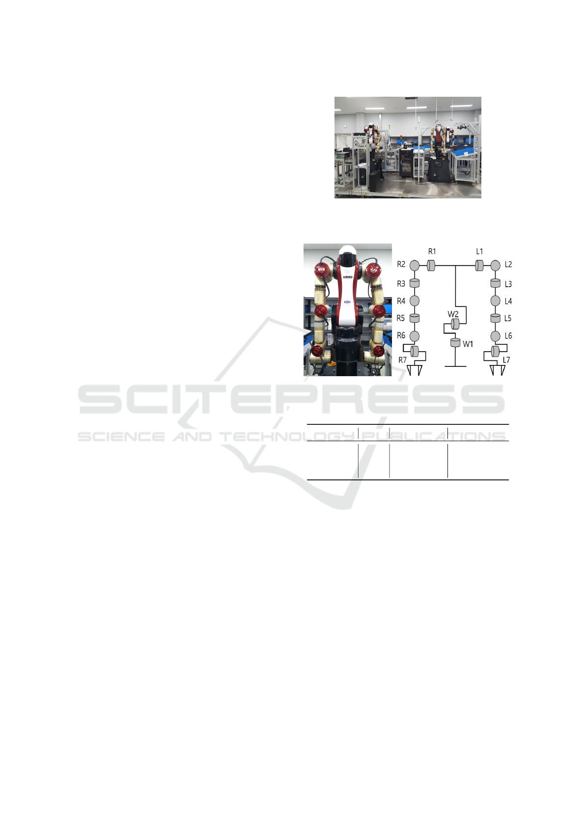
A IDAR, ambidextrous industrial robot (AMIRO)
of fig. 2, was developed. Its physical properties are
described in table 1. It has 7 DOF in each arms and
2 DOF in waist. Arm length is measured from shoul-
der to write. Body length is measured from shoul-
der to waist pitch axis. The payload to weight ratio
will be at least 1/2. All actuators and force-torque
sensors are communicated by the EtherCAT protocol.
EtherCAT is communication standard introduced by
BECKHOFF inc.. It uses the conventional local area
network (LAN) physical layer and hardware, so user
does not need to add any special equipment. In our
robot, hollow axis actuators and sensors are used and
all signals connected through the hole.
Figure 1: The developed robotic manufacturing system
to pack cellular phones with multiple industrial dual-arm
robots.
Figure 2: The developed industrial dual-arm robot,
’AMIRO’.
Table 1: Dual-arm robot specification.
DOF Weight(Kg) Length(mm)
Right arm 7 14.5 700
Left arm 7 14.5 700
Waist 2 14.0(Body) 570
3 REDUNDANCY CONTROL IN
THE INDUSTRIAL DUAL-ARM
ROBOT
3.1 Basic Idea
In robotic factory it is natural that IDARs cooperate
with human workers or work alone in human-familiar
environment. In this reason large room for the motion
to be easy is not provided for IDARs. Conventional
industrial robots are with fences that make a enough
room only for the robot. IDARs should consider col-
lision against to environment. To meet those prob-
lems IDAR need to increase DOF like human-beings.
The main advantage of redundancy is to be able to
perform secondary tasks and/or to choose which so-
lution suits us best. To this purpose, an optimization
ICINCO 2019 - 16th International Conference on Informatics in Control, Automation and Robotics
340
criterion can be set to find, within the set of IK so-
lutions, the one that performs best according to the
criterion. The most common procedure is to project a
gradient of a secondary task into the kernel of the Ja-
cobian matrix, in order not to affect much the position
error. With the redundancy IDAR can do secondary
tasks such as collision avoidance, acquiring joint mo-
tion margin, natural motion and so on.
There were many previous researches to control
redundant manipulators. ‘arm angle’ is utilized to de-
cide redundant arm posture in (Shimizu et al., 2008;
Seraji and Bon, 1999). In those ‘arm angle’ was de-
fined as angle between the plane configured by upper
and lower arm and ground. ‘arm angle’ can not be
defined for the dual-arm robot. Shoulder, those are
static as base position of each arm in ‘arm angle’ ap-
proach, moves in IDAR. In case of IDAR collision
avoidance with environments is possible with com-
plex algorithms. However those method can not be
run in the real robot control due to heavy computing
power.
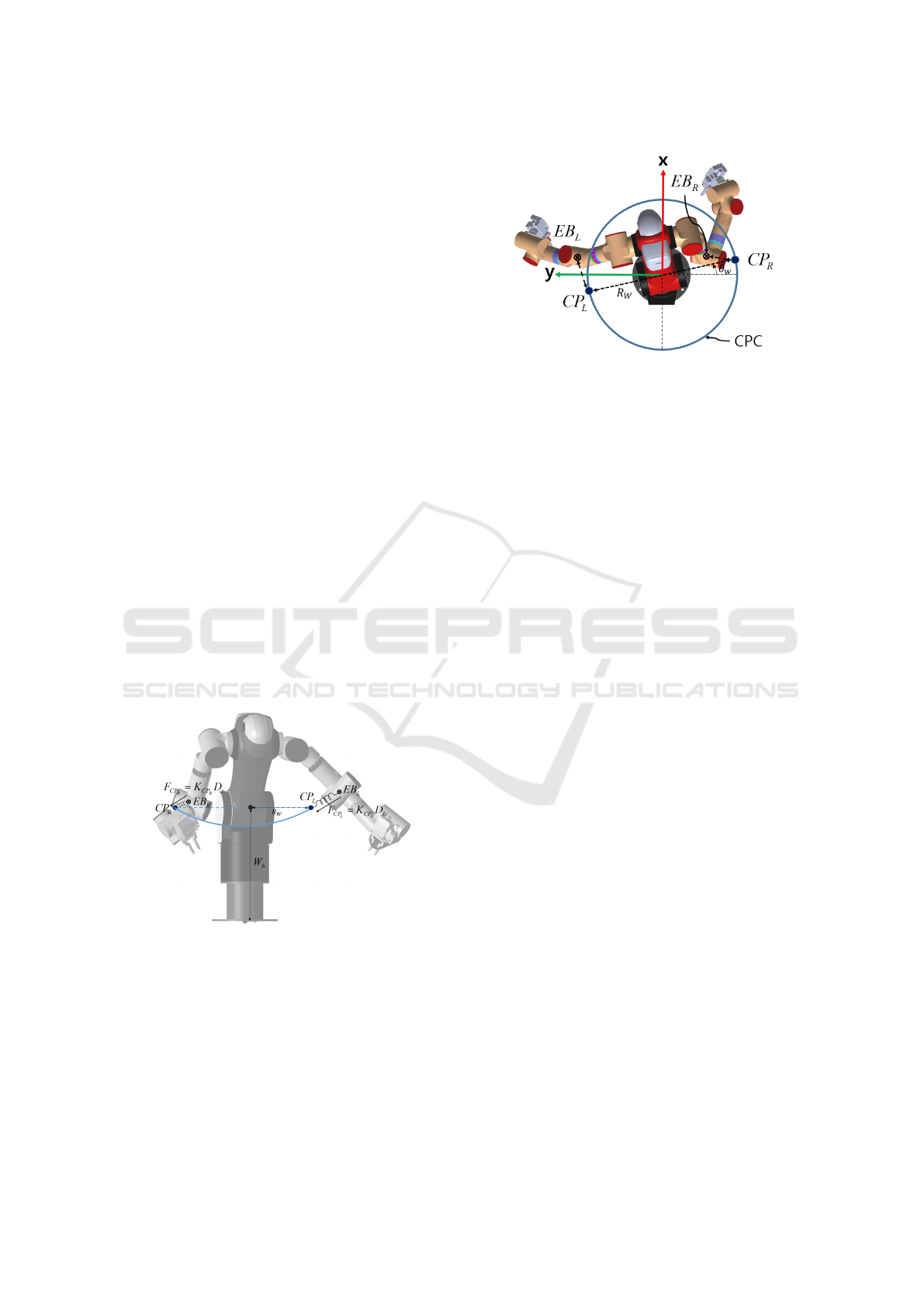
To make these problem simple a novel control
method is proposed, in which elbows are contracted
to the critical points (CP). C P can be determined as
temporary positions to constraint the motion. CP
R
and
CP
L
are shown in the fig. 3 for each right and left arm.
Virtual springs are positioned between CP
R
and EB
R
and between CP
L
and EB
L
. EB
R
and EB
L
are the el-
bow of right arm and left arm. Nominal length of
virtual springs set to zero, so virtual springs always
contract elbows by spring forces.
Figure 3: Conceptual view of the proposed method [front
view]. Virtual springs are positioned between CP and el-
bows (EB).
3.2 Virtual Spring based Elbow Control
It is noticeable that dynamics control scheme is not
used but gravity compensation because of lack of
real dynamic parameters in the proposed method. In
this reason virtual spring’s contraction forces does
not given to directly control laws. It is melted into
Figure 4: Conceptual view of the proposed method [top
view].
inverse kinematics (IK) solving problem. Although
there exists many methods to solve IK problem, the
most popular way is to use closed loop inverse kine-
matics (CLIK) algorithms, a first order jacobian ma-
trix is computed, which maps joint velocities into task
space velocities, and inverted to map the task space
error into a joint command difference which is likely
to reduce the task space error. Joint command is up-
dated with (1) and (2). To penalize singular points the
damped least square method is used like (3). Gradi-
ent projection in (4) is used to decide redundant joint
values.
θ
d
= θ
s
+
˙
θ
d
(1)
˙
θ
d
=
˙
θ
p
+
˙
θ
n
(2)
˙
θ
p
= (J
T
e
J
e
+ λ
2
I)
−1
J
T
e
˙x
d
(3)
˙
θ
n
= (I − J
†
e
J
e
)ν (4)
where θ
d
, θ
s
,
˙
θ
p
and
˙
θ
n
are a joint command, a joint
state, a joint command update from damped least
square and a joint command update in jacobian null
space for gradient projection. Jacobian pseudo in-
verse J
†
e
is described by (5) with a non-square jaco-
bian matrix J
e
and a damping parameter λ. ν is a gra-
dient.
J
†
e
= (J
T
e
J
e
+ λ
2
I)
−1
J
T
e
(5)
A cost value Φ is defined like (6) where χ
R
and χ
L
are
defined as power of contraction force between CP
R
and EB
R
, CP
L
and EB
L
, in each arm for convenience.
Details are described in (7) and (8).
Φ = χ
R
+ χ
L
(6)
χ
R
= F
CP
R
2
(7)
χ
L
= F
CP
L
2
(8)
Contraction forces F
CP
R
and F
CP
L
by virtual springs
are defined in (9) and (10).
F
CP
R
= K
CP
R
D
R
= K
CP
R
||EB
R
−CP
R
|| (9)
F
CP
L
= K
CP
L
D
L
= K
CP
L
||EB
L
−CP
L
|| (10)
Control of an Industrial Dual-arm Robot in a Narrow Space where Human Workers are Familiar with
341

where K
CP
R
and K
CP
L
are spring constants, D
R
and
D
L
are spring lengths, EB
R
and EB
L
are elbow po-
sitions, CP
R
and CP
L
are critical positions, in other
words, spring positions for each right and left virtual
springs. Distances of D
R
and D
L
are defined as (11)
and (12).
D
R
= ||EB
R
−CP
R
|| (11)
D
L
= ||EB
L
−CP
L
|| (12)
The gradient is defined as (13) to reduce cost
while robot working.
ν = −∇Φ = −
∂Φ
∂θ
= −[
∂Φ
∂θ
1
,
∂Φ
∂θ
2
, ...,
∂Φ
∂θ
n
]
T
(13)
where θ
i
are each joint states in n DOF robot for i =
{1, 2, ..., n}. Gradient is linearly decomposed as :
ν = −(
∂χ
R
∂θ
+
∂χ
L
∂θ
) (14)
Finally gradient becomes:
ν = −[
∂χ
R
∂θ
1
+
∂χ
L
∂θ
1
,
∂χ
R
∂θ
2
+
∂χ
L
∂θ
2
, ...,
∂χ
R
∂θ
n
+
∂χ
L
∂θ
n
]
T
(15)
EB
R
, EB
L
, CP
R
and CP
L
are defined as (16), (17),
(18) and (19).
EB
R
= (EB
R
x
, EB
R
y
, EB
R
z
) (16)
EB
L
= (EB
L
x
, EB
L
y
, EB
L
z
) (17)
CP
R
= (CP
R
x
, CP
R
y
, CP
R
z
) (18)
CP
L
= (CP
L
x
, CP
L
y
, CP
L
z
) (19)
χ
R
and χ
L
from (7) and (8) are expanded to (20) and
(21) with (11)∼(19).
χ
R
=K
CP
R
2
(D
R
x
2
+ D
R
y
2
+ D
R
z
2
) (20)
χ
L
=K
CP
L
2
(D
L
x
2
+ D
L
y
2
+ D
L
z
2
) (21)
where D
R
x
, D
R
y
, D
R
z
, D
L
x
, D
L
y
and D
L
z
are follow-
ings:
D
R
x
= EB
R
x
−CP
R
x
(22)
D
R
y
= EB
R
y
−CP
R
y
(23)
D
R
z
= EB
R
z
−CP
R
z
(24)
D
L
x
= EB
L
x
−CP
L
x
(25)
D
L
y
= EB
L
y
−CP
L
y
(26)
D
L
z
= EB
L
z
−CP
L
z
(27)
Each terms of
∂χ
R
∂θ
i
and
∂χ
L
∂θ
i
in (15) are more de-
scribed in detail as (28) and (29) for i = 1, 2, ..., n with
(20) and (21).
∂χ
R
∂θ
i
= 2K
CP
R
2
(D
R
x
∂D
R
x
∂θ
i
+ D
R
y
∂D
R
x
∂θ
i
+ D
R
z
∂D
R
x
∂θ
i
)
(28)
∂χ
L
∂θ
i
= 2K
CP
L
2
(D
L
x
∂D
L
x
∂θ
i
+ D
L
y
∂D
L
x
∂θ
i
+ D
L
z
∂D
L
x
∂θ
i
)
(29)
Partial differential of (22)∼(27) can be determined
with the jacobians between origin to elbows; J
R
EB
and
J
L
EB
. Those jacobians can be achieved easily with ad-
ditional light calculations.
∂D
R
x
∂θ
i
= J
R
EB
(1, i) −
∂C P
R
x
∂q
i
(30)
∂D
R
y
∂θ
i
= J
R
EB
(2, i) −
∂C P
R
y
∂q
i
(31)
∂D
R
z
∂θ
i
= J
R
EB
(3, i) −
∂C P
R
z
∂q
i
(32)
∂D
L
x
∂θ
i
= J
L
EB
(1, i) −
∂C P
L
x
∂q
i
(33)
∂D
L
y
∂θ
i
= J
L
EB
(2, i) −
∂C P
L
y
∂q
i
(34)
∂D
L
z
∂θ
i
= J
L
EB
(3, i) −
∂C P
L
z
∂q
i
(35)
where J
R
EB
(p, q) and J
L
EB
(p, q) are elements of jaco-
bian matrix at pth row and qth column for each elbow
of right and left arms.
4 SIMULATION STUDY
A simulation is conducted to show the effectiveness of
the proposed method. A WIDAR positioned instead
of a human-workers. CPs are determined as described
in section 4. User parameters of R
w
and W
h
are set as
0.3m and 0.57m from the dimension of AMIRO.
Fig. 5a shows dual-arm motion with the conven-
tional method, in other words there is no constraint on
elbow positions. Fig. 5b is with the proposed method.
Elbows are contracted to the CPs on the CPC. Cir-
cles of A and A
0
are right end-effector motion for each
method, and they are exactly same. Circles of B and
B
0
are left end-effector motion, and they are same too.
Fig. 6a and 6b show trajectories of end effectors.
Trajectories of the conventional method and the pro-
posed method are exactly same because both use same
damping variables. The proposed method use null
space to get redundant motions of elbows. However
elbow motion is quite different. In the conventional
method the motion of elbow is stick to minimum ve-
locity criteria without constraints. That causes the
smallest movements of elbows to reach a goal. In the
proposed method elbows are forced to go to the deter-
mined CPs. Fig. 7 shows trails of elbow positions in
three dimensional (3D) space. Fig. 8, 9 and 10 show
same trails in each xy, xz and yz plane.
Contraction force between CP
R
and EB
R
is plotted
in Fig. 11a. Contraction force between CP
L
and EB
L
is plotted in fig. 11b. In the proposed method con-
traction forces are decreased if it can, that means the
ICINCO 2019 - 16th International Conference on Informatics in Control, Automation and Robotics
342
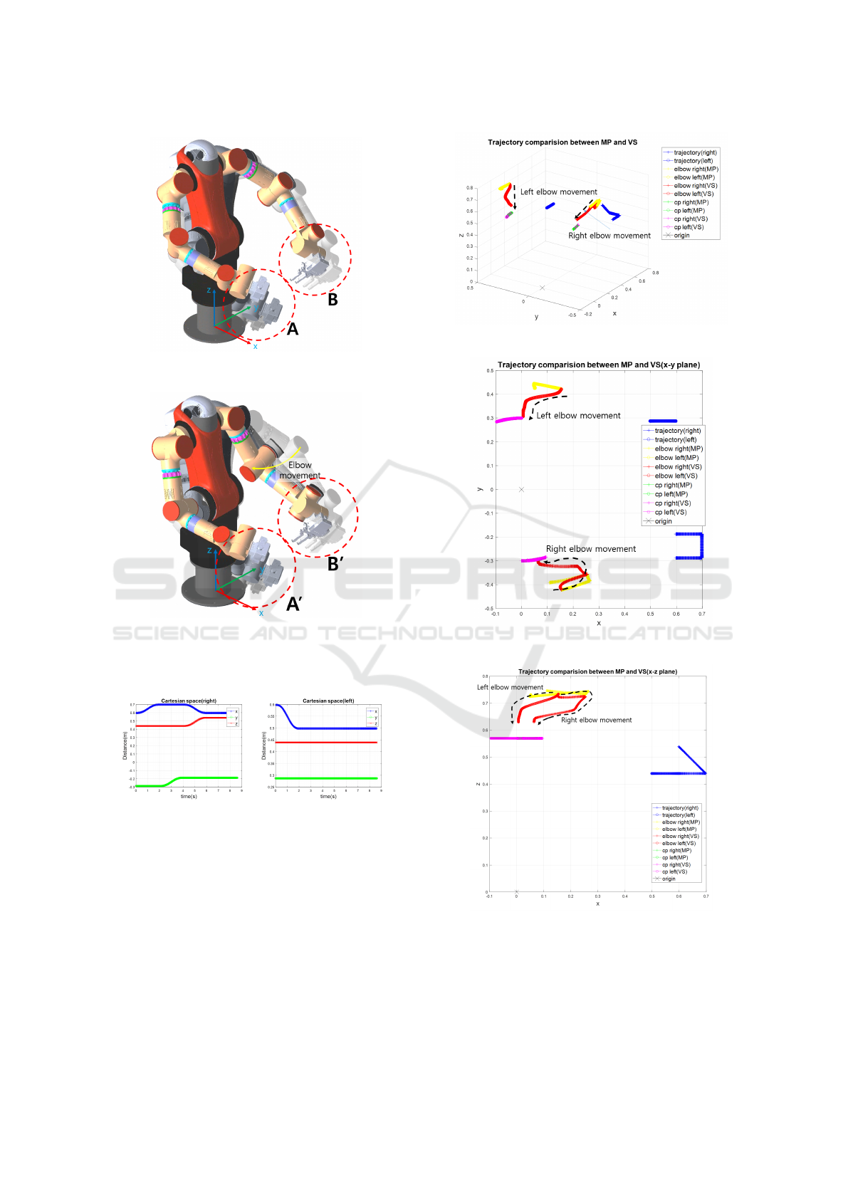
(a) Dual-arm robot motion with Moore-
Penrose method.
(b) Dual-arm robot motion with the pro-
posed method.
Figure 5: Comparison of dual-arm robot motions.
(a) Right. (b) Left.
Figure 6: The end-effector trajectory.
distances between CPs and EBs are reduced as short
as possible. In fig. 11a contraction force increase for
a while after 1sec. It is because elbow motions run
without effect on end-effector positions.
5 CONCLUSION
Dual-arm robot is a novel industrial robot with two
arms. It has high redundancy in motion inevitably.In
Figure 7: Trajectories(elbow, CP, end-effector).
Figure 8: Trajectories in xy plane(elbow, CP, end-effector).
Figure 9: Trajectories in xz plane(elbow, CP, end-effector).
practical both arms cause undesired motions includ-
ing colliding against to environments without proper
control. To resolve this problem a novel control
method is proposed in this paper. The proposed
method try to limit elbows motion to be contracted to
Control of an Industrial Dual-arm Robot in a Narrow Space where Human Workers are Familiar with
343
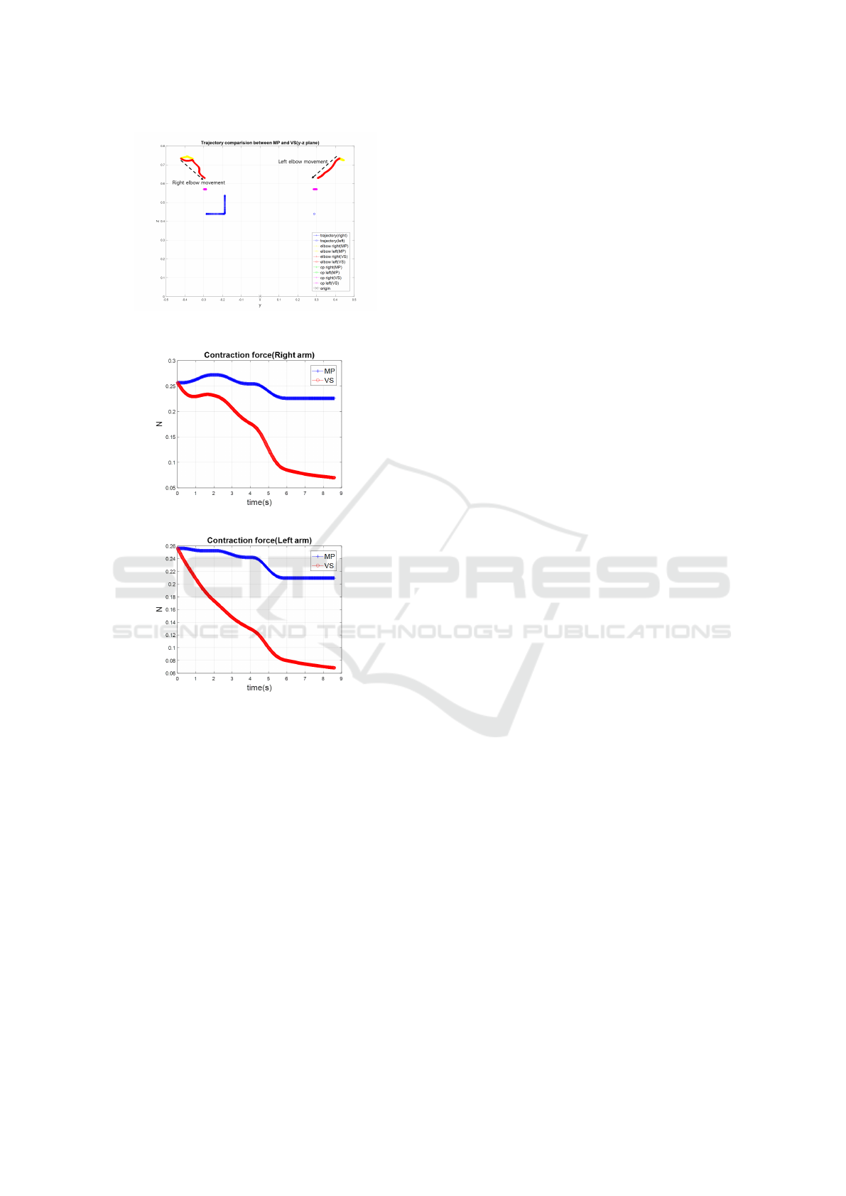
Figure 10: Trajectories in yz plane(elbow, CP, end-effector).
(a) Contraction force(right).
(b) Contraction force(left).
Figure 11: Contraction force.
the contraction points via virtual springs algorithm.
Contraction points are decided to mimic the motion
of human worker. In simulation studies the proposed
algorithm induced the desired motion to control re-
dundant dual-arm robot.
REFERENCES
ABB (2019). How human-robot collaboration is driving a
manufacturing revolution.
Colom
´
e, A. and Torras, C. (2012). Redundant inverse kine-
matics: Experimental comparative review and two
enhancements. In Intelligent Robots and Systems
(IROS), 2012 IEEE/RSJ International Conference on,
pages 5333–5340. IEEE.
Do, H. M., Choi, T.-Y., and Kyung, J. H. (2016). Au-
tomation of cell production system for cellular phones
using dual-arm robots. The International Journal of
Advanced Manufacturing Technology, 83(5-8):1349–
1360.
Hayakawa, Y., Kitagishi, I., and Sugano, S. (1998). Human
intention based physical support robot in assembling
work. In Proceedings of IROS, pages 930–935.
Kruger, J., Lien, T., and Verl, A. (2009). Cooperation of
human and machines in assembly lines. CIRP Annals-
Manufacturing Technology, 58(2):628–646.
Morioka, M. and Sakakibara, S. (2010). A new cell produc-
tion assembly system with human-robot cooperation.
CIRP Annals-Manufacturing Technology, 59(1):9–12.
Seraji, H. and Bon, B. (1999). Real-time collision avoid-
ance for position-controlled manipulators. Robotics
and Automation, IEEE Transactions on, 15(4):670–
677.
Shimizu, M., Kakuya, H., Yoon, W.-K., Kitagaki, K., and
Kosuge, K. (2008). Analytical inverse kinematic com-
putation for 7-dof redundant manipulators with joint
limits and its application to redundancy resolution.
Robotics, IEEE Transactions on, 24(5):1131–1142.
Smith, C., Karayiannidis, Y., Nalpantidis, L., Gratal, X.,
Qi, P., Dimarogonas, D. V., and Kragic, D. (2012).
Dual arm manipulation—a survey. Robotics and Au-
tonomous systems, 60(10):1340–1353.
Yaskawa (2019). Slim dual-arm robot.
ICINCO 2019 - 16th International Conference on Informatics in Control, Automation and Robotics
344
