
Sum-rate Optimal Communication under Different Power Constraints
Mohammad Kaisb Layous Alhasnawi
1,2
and Ronald G. Addie
2
1
Faculty of Administration and Economics, Sumer University, Thi-Qar, Iraq
2
School of Agricultural, Computational and Environmental Science, University of Southern Queensland,
Keywords:
SS-OFDM, OFDMA, Power Limits, EMF Constraints, Time Segregated, Efficient Power Management,
CSMA/CA, Friis Formula.
Abstract:
In this paper the problem of optimal allocation of power to different devices and spectrum when communi-
cation takes place in the same region, using shared spectrum, is investigated. We assume that there must be
constraints on the power, or EMF, used at each device participating in the shared communication. We consider
different forms of power/EMF constraint and compare the sum-throughput achieved by all devices, under these
different constraints.
1 INTRODUCTION
Since the introduction of CDMA more than twenty
years ago, it has been understood that efficient use
of spectrum resources is to a high degree connected
with power management, i.e. the choice of how much
power is used by each device, in each part of the
available spectrum. In the commercial deployment
of CDMA, nearly orthogonal codes were used, which
gives the impression that efficient power management
relies on the shared use, i.e. overlapping use, of
spectral resources. However, in this paper we ar-
gue that efficient power management is actually bet-
ter explained by the concept that meeting the power
constraint is inherently a shared responsibility. Even
when different devices use orthogonal resources, such
as transmission at different times, or in different fre-
quencies, the collection of devices communicating in
the same geographical region at approximately the
same time share responsibility for keeping the total
field strength of transmitted signals below a regulated
level.
Orthogonal Frequency Division Multiple Access
(OFDMA) has strong support as the radio transmis-
sion technology for the next generation of cellular
mobile wireless systems (Yang, 2010; Yadav et al.,
2017). OFDMA is a variant of OFDM which also
implements frequency division multiple access, using
the orthogonal sub-frequencies. This scheme is used
in several generations mobile systems such as 3GPP
Long Term Evolution (LTE), and IEEE 802.16m ad-
vanced WiMAX.
The paper is organized as follows with the ar-
rangement; Section 2 provides the background about
OFDM system and explains the mathematical model
by using Shannon Bound theory to a model wireless
system. Section 3 compares throughput under the
five different configurations; time-segregated trans-
mission, OFDMA, EMF constrained, SS-OFDM,
and mutually interfering. The maximum sum-rate
throughput for each of the power allocation and shar-
ing those five configurations will determine at Section
4. Section 5 displays the throughput model imple-
mented in Netml. The conclusion is set out in Section
6.
2 BACKGROUND
2.1 Relationship between OFDMA and
Sum-rate Optimality
OFDMA is one of the most important multiple access
schemes for wireless networks (Yang, 2010; AlSab-
bagh & Ibrahim, 2016). It has all the communication
advantages of OFDM together with efficient sharing
of spectral resources (AlSabbagh & Ibrahim, 2016;
Castro e Souza et al., 2016).
In broadband multiple access, a significant per-
formance measure is the sum-rate capacity. An im-
portant question which is investigated in this paper is
whether, and in what sense, is OFDMA sum-rate op-
timal, i.e. does it acheive, under the appropriate con-
Alhasnawi, M. and Addie, R.
Sum-rate Optimal Communication under Different Power Constraints.
DOI: 10.5220/0007957203730380
In Proceedings of the 16th International Joint Conference on e-Business and Telecommunications (ICETE 2019), pages 373-380
ISBN: 978-989-758-378-0
Copyright
c
2019 by SCITEPRESS – Science and Technology Publications, Lda. All rights reserved
373
straints, the optimal total throughput achievable by a
given collection of communicating devices?
(Li & Liu, 2007) investigated sum rate optimal-
ity of an OFDMA system in an uplink. They found
conditions under which OFDMA is sum-rate optimal.
They found that the gap between OFDMA and the op-
timal solution is very small when the number of sub-
channels is large. Also, they investigated maximiz-
ing the sum rate of an OFDMA system in the uplink
multi-carrier situations with a limited number of sub-
channels.
2.2 System Model
The model used here is similar to that of (Chen &
Oien, 2008) except that as well as n separate power
constraints, we also consider a uniform constraint on
total EMF. This constraint also applies at all of the
nodes (both origins and destinations) of the network,
but it is reasonable to suppose that the constraint is
now the same at all nodes. This does not imply that
all nodes are transmitting with the same power.
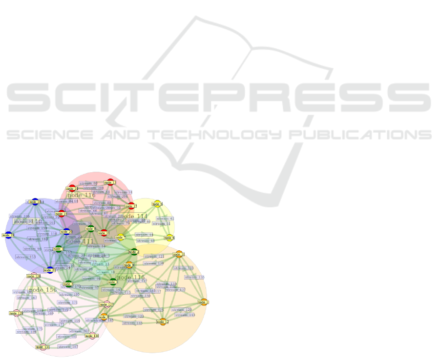
2.3 Overlapping Wireless Domains
From the fact that we can get close to the Shannon-
Hartley bound, it follows that we can use it to esti-
mate system capacity. This is useful in itself, as a
simple and effective way to model wireless systems.
For example, we can use this principle to model the
bandwidth which can be achieved in a configuration
of access points and users of the sort depicted in Fig-
ure 1.
Figure 1: Six wireless networks sharing spectrum.
Currently, the conventional way to model such
a system would be to simulate it, for example, us-
ing Ns3 (Henderson et al., 2008), Omnet (Varga &
Hornig, 2008), or Opnet (Guo et al., 2007). How-
ever, setting up such a simulation would be very time
consuming and would not necessarily provide useful
insight into spectrum sharing.
The study (Alhasnawi et al., 2018) also used the
Shannon Hartley bound to model the capacity of wire-
less communication systems.
3 POWER/EMF CONSTRAINTS
To meet regulations and standards governing wire-
less communication, all wireless devices must limit
the power of their transmissions. This effectively also
limits the total EMF generated by these transmissions.
In this paper we seek to compare and contrast differ-
ent approaches to regulating or limiting EMF and/or
power.
If shared use of spectrum is mediated by time-
segregated use, which is often the case (e.g. as in
CSMA/CA), a limit on the power transmitted by any
device imposes a constraint on the total electrical field
strength (and magnetic field strength), which can oc-
cur. Regulations on transmission power are not neces-
sarily imposed for this purpose, however, as the num-
ber of devices sharing the same physical and spectral
location increases, it may become appropriate, or nec-
essary to view regulation of power in this light, i.e. as
a means to limit total electromagnetic field strength.
Suppose there are n transmissions required to take
place, as shown in Figure 10, let the transmission
power at source k be denoted by P
k
, and suppose the
maximum power allowed to be transmitted, in order
to regulate total EMF, is T
P
. More precisely, if there
was only one transmitter, in order to acheive the de-
sired limit on EMF, it could not transmit with more
power than T
P
. We now consider five different ap-
proaches to limiting power which vary in the way the
aggregate EMF due to all the devices is considered.
Note that the five different approaches to meet-
ing power/EMF constraints that are considered here
vary slightly in the way the constraint is expressed,
but also, and this is the more significant aspect, in the
way in which the constraint is enforced.
These five approaches are:
1. Carrier-sense multiple access (CSMA) method,
the modeling of which is presented in Subsection
3.1,
2. Orthogonal Frequency-Division Multiple Access
(OFDMA), treated in Subsection 3.2,
3. Electromagnetic Fields (EMF) limited, in Subsec-
tion 3.3,
WINSYS 2019 - 16th International Conference on Wireless Networks and Mobile Systems
374

4. Spread Spectrum-Orthogonal Frequency Division
Multiplexing (SS-OFDM), in Subsection 3.4, and,
5. mutually interfering (i.e. all transmitters use the
entire bandwidth, simultaneously, treating each
other as noise), treated in Subsection 3.5.
The purpose of this comparison is not simply to
show that one approach has more throughput than
another. For example, it will always produce lower
throughput when EMF is adopted as the appropriate
constraint, rather than transmitted power at each de-
vice. The reason for comparing these constraints is
that an EMF constraint is more rigorous, and therefore
safer. The experiments show that adopting this con-
straint does not dramatically reduce throughput rela-
tive to a constraint on power, and that is the conclu-
sion of interest from these particular experiments.
Likewise, the transmission model adopted is very
simple and cannot be used as the basis for designing
a communication system. We assume that all com-
munication systems use OFDM with careful chan-
nel estimates made dynamically during actual oper-
ation. The simple transmission model is being used
to compare throughput under the five different con-
figurations which are compared, and is sufficient for
that purpose.
3.1 Time-segregated Transmission
If all devices communicate only when others are idle,
and when this is the case they use all the available
spectrum, the power constraints can be expressed
thus:
P
n
≤ T
p
, n = 1,...,N (1)
These constraints also ensure that at every location,
the EMF never exceeds the EMF which would be gen-
erated by one device transmitting continuously at the
limit power.
3.2 OFDMA
In this case, the power constraints are still expressed
by (1). However, because the devices are able to
transmit simultaneously, total throughput can be quite
different, as shown in the Section 5.
3.3 EMF Constrained
Let
G =
g
11
... g
1n
.
.
.
.
.
.
.
.
.
g
n1
... g
nn
where g
jk
is the received power at node k due to the
transmission from node j, if j 6= k, or 1 otherwise.
These values can be estimated from Friis transmission
formula (Popovi
´
c & Popovi
´
c, 2000):
g
jk
=
DA
4πr
2
jk
(2)
in which D is the directivity of the aerial at node S
j
,
the source of transmission j , A denotes the relative
effective area of the receiving aerial (i.e. the human
body) at node S
k
, the source of transmission k, and r
jk
is the distance between the source of transmission j
and the source of transmission k. By relative effective
area of the aerial at node S
k
we mean how much less
effective a human present at node S
k
is, at receiving
power from a distant aerial, than they are at receiving
power from the source of transmission k. Hence, a
simple choice for A is 1.
A constraint on total EMF due to all transmis-
sions, at all the sources, can therefore be expressed
in the form:
n
∑
j=1
g
k, j
P
j
≤ T
p
, k = 1,..., n. (3)
3.4 SS-OFDM
Now suppose we use codes, either orthogonal codes
or nearly orthogonal ones, in conjunction with
OFDM. Thus, codes are used to mediate access rather
than frequencies, as in OFDMA. The case where the
codes are orthogonal is, in many respects, no different
from OFDMA.
Two approaches to limiting power can be distin-
guished in this case: (a) a simple limit on total power,
as in OFDMA, and (b) a limit on total EMF, as in the
EMF-limited case. Since the two cases are very sim-
ilar, we shall confine our investigation in this case to
the second of these alternatives.
In this case, the constraints on power are also
expressed by (3). If the codes are orthogonal, the
throughput will also be the same as in the previous
case. A formula for the throughput when the codes
are not orthogonal is given in Section 4.5. The only
difference is that in this case the power spectral den-
sity of the transmitted signal will be different. By ju-
dicious use of codes it should be feasible to achieve a
virtually flat power spectral density.
However, if the codes are nearly orthogonal, as in
(Alhasnawi et al., 2018), the throughput of this sys-
tem will be quite different, and provides an approach
intermediate between that of Subsection 3.3 and 3.5.
Sum-rate Optimal Communication under Different Power Constraints
375

3.5 Mutually Interfering
In this case, also, the constraints on power are also ex-
pressed by (3). Instead of seeking complete indepen-
dence of different transmissions, by using of time, fre-
quency, or code segregation, in this case we make no
attempt to prevent interfence between different trans-
missions, and simply allow them to proceed simulta-
neously, with each transmitter treating the others as
white noise. We may suppose, for example, that each
uses a unique coding which ensures that its signal ap-
pears, statistically, as white noise for the others. In a
situation where transmitters are far from each other, or
where background noise is already of relatavely high
power, this approach will be nearly optimal.
4 SUM-RATE OPTIMAL
THROUGHPUT
The transmitters sharing the available spectrum are
always assumed, when time, frequency, or code re-
sources are shared, to be allocated equal shares. It is
therefore possible that higher throughputs than those
we obtain below could be attained by unequal allo-
cation of resources. Our intention in this paper is
primarily to compare the different sharing strategies
rather than to optimize throughput as such. In any
case, since focussing on total throughput would often
result in some users being allowed no resources at all,
it is unlikely that total throughput in this sense is an
appropriate objective.
In this section we determine the maximum sum-
rate throughput, per Hz, for each of the power allo-
cation and sharing schemes considered in Section 3.
We assume that each transmitter has identical access
to communication resources – allocation of these re-
sources is not optimized. Rather, it is allocation of
power to the resources which is under consideration.
Mainly we seek to compare the throughput achieved
by the alternative schemes, under different network
conditions.
In the first two cases (time segregated, and individ-
ual power constraints), the optimal power allocation
to devices is obvious. In both these cases, devices
simply transmit at their maximum power, while they
are active.
In the EMF-constrained case, set out in Subsec-
tion 3.3, the vector of power levels is P = (P
1
,... ,P
N
)
0
where
P = T
P
G
−1
u (4)
Where u is a vector of 1
0
s and ∗
0
s. If u
j
= ∗ we
require P
j
= 0. In other words, we select a subset of
sources to transmit at full power and another set of
sources that will be idle. One such selection will be
optimal.
To work out which ones should be transmitting
and which should not, consider a small change to
the power of a transmitter, along with the consequen-
tial changes to all other transmitters which keep them
within their constraint. If this change leads to more
throughput, with more power, then this should be one
of the transmitters.
The special case where all sources are transmit-
ters will occur frequently because the matrix G will
frequently have rather small off-diagonal terms. In
this case the vector u, at (4), consists of all 1’s.
The total throughput of the system is the same as the
sum rate, which is the objective of the multiplexing
and channel allocation problem considered in this pa-
per. This objective is expressed mathematically in
Equation (4) in (Chen & Oien, 2008). In their formu-
lation, the signal from each communication interferes
with all others, and appears as white noise of the same
power.
4.1 Time-segregated Transmission
In this case each transmitter operates at power P
n
= T
P
while it is transmitting. The total rate of transmission,
in bits/s/Hz, in this case is
N
∑
n=1
1
N
log
2
1 +
P
n
G
n,n
σ
2
n
. (5)
4.2 OFDMA
Because the power allocated to the bandwidth as-
signed to each transmitter is the whole of the allo-
cated power, for this transmitter, i.e. P
n
= T
P
, while
the noise is just a
1
N
-th share, and the bandwidth for
each transmitter is
1
N
-th of the whole, the total rate of
transmission, in bits/s/Hz, in this case is
N
∑
n=1
1
N
log
2
1 + N
P
n
G
n,n
σ
2
n
. (6)
4.3 EMF Constrained
The throughput in the EMF-limited case is also given
by (6), except that in this case the P
n
are given by (4).
4.4 SS-OFDM
In this case, as well as background noise, receiver n
experiences user noise, u
2
n
, which is given by the for-
mula
WINSYS 2019 - 16th International Conference on Wireless Networks and Mobile Systems
376
u
2
n
=
∑
k6=n
cP
k
G
k,n
(7)
in which c is the correlation between codes, which we
assume is the same for all pairs of codes. Naturally
0 ≤ c ≤ 1; in the case c = 0, we say the codes are
orthogonal. Throughput is therefore,
N
∑
n=1
1
N
log
2
1 +
P
n
G
n,n
σ
2
n
/N + u
2
n
. (8)
4.5 Mutually Interfering
In this case, as in the previous case, as well as back-
ground noise, receiver n experiences user noise, u
2
n
,
which is now given by the formula
u
2
n
=
∑
k6=n
P
k
G
k,n
(9)
Each transmitter is active all the time, and receivers
experience the full background noise, so throughput
is
N
∑
n=1
log
2
1 +
P
n
G
n,n
σ
2
n
+ u
2
n
. (10)
5 EXPERIMENTS
The throughput model from the previous section has
been implemented in Netml (Addie et al., 2011;
Addie & Natarajan, 2015) allowing for five differ-
ent sharing strategies, namely CSMA/CA, OFDMA,
EMF-constrained OFDMA, mutually-interfering (i.e.
all transmitters use the entire bandwidth, simultane-
ously, treating each other as noise), and SS-OFDM.
This model of sharing which has been implemented in
the Netml system is not the same as simulation, and
is therefore not available in alternative systems like
Opnet, Omnet, or ns-3. Equations (2), (5)–(10) have
been used to estimate throughput, instead of simula-
tion. This is much faster and, since it focusses on
principles underlying shared use of spectrum, more
appropriate in the present context.
The precise values of received power and SNR at
each receiver, in (9), depend on the power levels at
the transmitters and gain across each pair (G
n,n
), and
hence on the geographical layout of the pairs. All
these parameters are relatively easy to calculate once
the layout has been determined. Using the Netml sys-
tem, different configurations of communicating pairs
can easily be created, the distances between all nodes
calculated, the power levels allowed by the constraints
for the particular case determined, the gain matrix G
calculated by means of (2), and the total throughput
calculated.
We have undertaken three experiments, in each of
which the geographical configuration of the pairs of
communicating devices is arranged somewhat differ-
ently. The three cases considered are as follows:
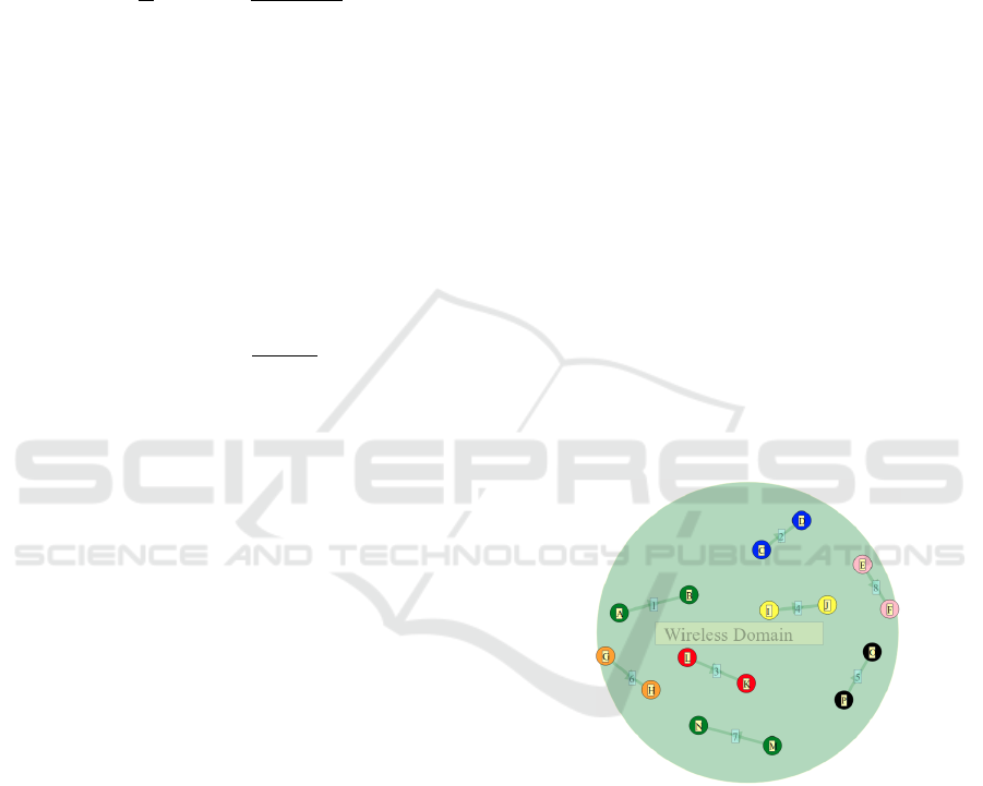
(i) the nodes of each pair are relatively close to each
other and the pairs are widely separated. There
are 8 pairs of nodes. This case is referred to as
widely separated pairs, as shown in Figure 2.
(ii) The pairs are closer together than in the previous
case, and there is only three pairs, as in Figure
5. This case is referred to as three close pairs.
(iii) In this case eight pairs overlap. We refer to this
case as overlapping pairs, as in Figure 8.
5.1 Widely Separated Pairs
The results, plotted in Figure 3, show that the sum-
throughput rate of OFDMA and EMF-constrained
OFDMA was equal for all levels of background noise.
Total throughput in the CSMA/CA case was always
worse than OFDMA and quite significantly so for
high levels of noise.
The mutually interfering and SS-OFDM total
throughputs were very similar and both were also sim-
ilar to OFDMA for high noise levels, but a little worse
than OFDMA for low noise.
Figure 2: Eight widely separated pairs of nodes.
The power of the signal in each frequency range,
when OFDMA is used, has been calculated as well as
throughput, and is shown in Figure 4. The power vs
frequency distribution will be the same in the EMF-
limited case. In the time-segregated case, the SS-
OFDM case, or the mutually interfering case, the
power vs frequency distribution will be essentially
flat.
5.2 Three Close Pairs
The results in this case, plotted in Figure 6 exhibit the
same key features: OFDMA and EMF-limited cases
Sum-rate Optimal Communication under Different Power Constraints
377
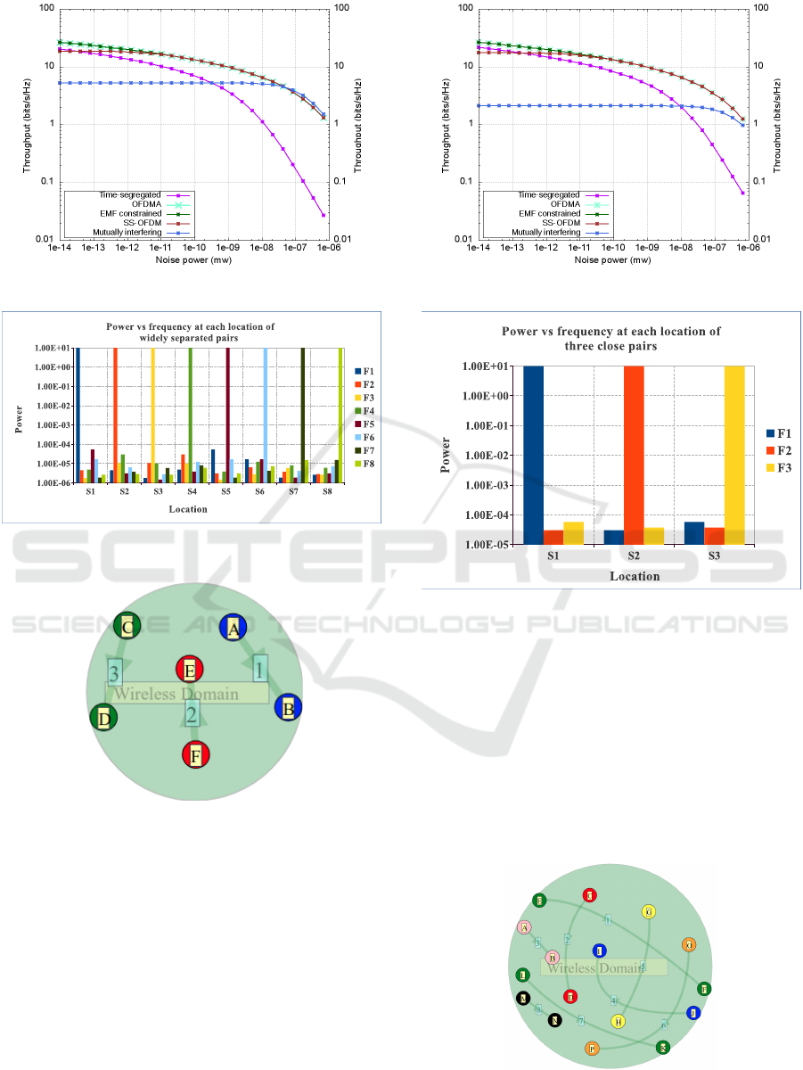
Figure 3: Wireless throughput for widely separated pairs.
Figure 4: Power vs frequency for widely separated pairs.
Figure 5: Three pairs of close nodes.
are almost identical and deliver better throughput than
all other cases. CSMA/CA is worse, and more signif-
icantly so under high noise. The SS-OFDM case is
closer to OFDMA but a little worse under low noise.
One difference from the previous experiment is that
now the mutually interfering case exhibits worse per-
formance than SS-OFDM.
The power of the signal in each frequency range,
when OFDMA or the EMF-limited case applies, has
been calculated and is shown in Figure 7. In the time-
segregated case, the SS-OFDM case, or the mutually
interfering case, the power vs frequency distribution
will be, as in the first experiment, essentially flat.
Figure 6: Wireless throughput for three close pairs of nodes.
Figure 7: Power vs frequency at each source location of
three close pairs.
5.3 Overlapping Pairs
The results, plotted in Figure 9, again show that the
OFDMA and EMF-limited cases have higher total
throughput than all others. CSMA/CA is again signif-
icantly worse for high noise, and SS-OFDM is close
to OFDMA, but a little worse for low noise. Also,
the mutually interfering case is worse again than SS-
OFDM.
Figure 8: Overlapping communicating pairs.
WINSYS 2019 - 16th International Conference on Wireless Networks and Mobile Systems
378
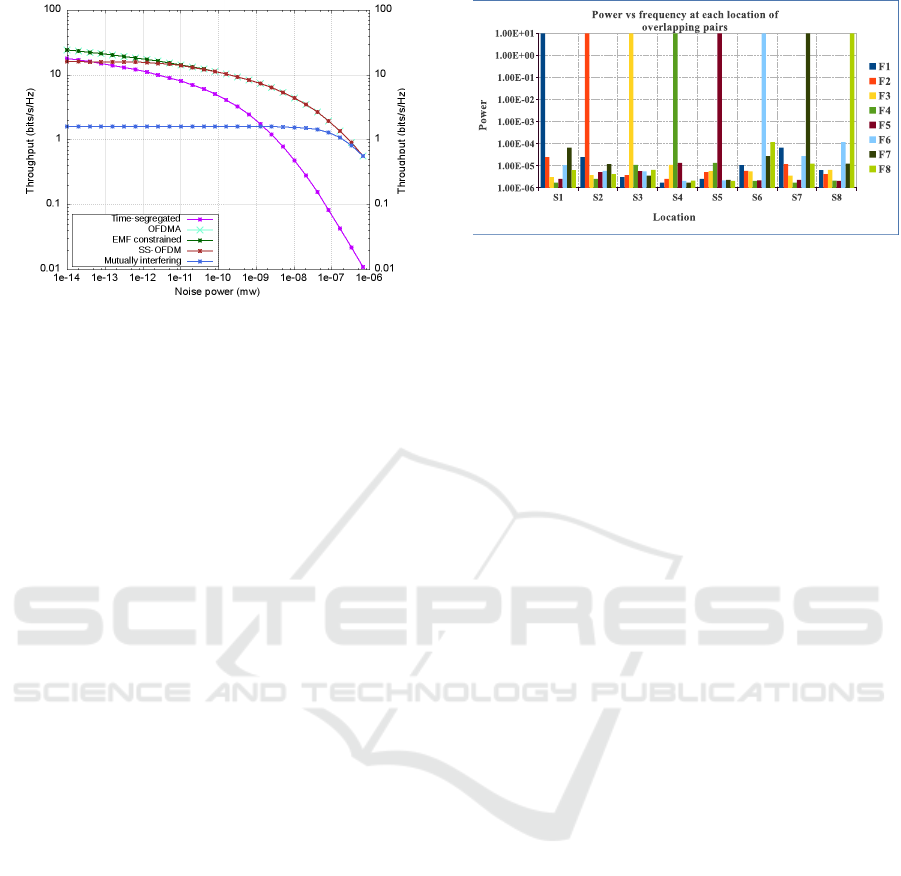
Figure 9: Wireless throughput of overlapping communicat-
ing pairs.
The power of the signal in each frequency range,
in the OFDMA or EMF-limited cases, has been cal-
culated and is shown in Figure 10. In the time-
segregated case, the SS-OFDM case, or the mutually
interfering case, the power vs frequency distribution
will be, as in the previous experiments, essentially
flat.
6 CONCLUDING REMARKS
The experiments all show that OFDMA and the EMF-
limited cases are nearly identical. This is because in
all the cases considered, the EMF limits on power are
not significantly different from simply limiting the
transmitted power of each device. If configurations
where devices are very close together were consid-
ered, this would no longer be the case. Consideration
of such cases remains for future work.
Another consistent result was that OFDMA con-
sistently out-performed all other sharing mechanisms.
The SS-OFDM case assumed non-orthogonal codes,
with correlation at the level 0.1. If orthogonal codes
were used, the performormance of SS-OFDM would
be identical to OFDMA. Such experiments were con-
ducted, but not shown, because the two performance
curves would simply be superimposed.
However, the spectral distribution of SS-OFDM is
essentially flat, unlike that of OFDMA. If this is an
important consideration, SS-OFDM is therefore the
preferred option. It acheives the same throughput as
OFDMA, but within a much tighter constrant on the
power spectral density.
Figure 10: Power vs frequency at each source location of
overlapping pairs.
REFERENCES
Addie, R. & Natarajan, J. P. R. (2015). Netml-ns3-click:
modeling of routers in netml/ns3 by means of the
click modular router. In Proceedings of the 8th In-
ternational Conference on Simulation Tools and Tech-
niques (pp. 293–295).: ICST (Institute for Com-
puter Sciences, Social-Informatics and Telecommuni-
cations Engineering).
Addie, R. G., Peng, Y., & Zukerman, M. (2011). Netml:
networking networks. In Dependable, Autonomic and
Secure Computing (DASC), 2011 IEEE Ninth Interna-
tional Conference on (pp. 1055–1060).: IEEE.
Alhasnawi, M. K. L., Addie, R. G., & Abdulla, S. (2018).
A new approach to spread-spectrum ofdm. In Pro-
ceedings of the 15th International Joint Conference
on e-Business and Telecommunications - Volume 2:
ICETE, (pp. 281–288).: INSTICC SciTePress.
AlSabbagh, H. M. & Ibrahim, M. K. (2016). Adaptive
OFDMA resource allocation using modified multi-
dimension genetic algorithm. Iraqi Journal for Elec-
trical And Electronic Engineering, 12(1), 103–113.
Castro e Souza,
´
A. R., de Almeida Amazonas, J. R., &
Abr
˜
ao, T. (2016). Energy-efficiency maximisation
for cooperative and non-cooperative OFDMA cellu-
lar networks—a survey. Transactions on Emerging
Telecommunications Technologies, 27(2), 216–248.
Chen, C. S. & Oien, G. E. (2008). Optimal power alloca-
tion for two-cell sum rate maximization under min-
imum rate constraints. In 2008 IEEE International
Symposium on Wireless Communication Systems (pp.
396–400).: IEEE.
Guo, J., Xiang, W., & Wang, S. (2007). Reinforce network-
ing theory with opnet simulation. Journal of informa-
tion technology education, 6, 215–226.
Henderson, T. R., Lacage, M., Riley, G. F., Dowell, C., &
Kopena, J. (2008). Network simulations with the ns-3
simulator. SIGCOMM demonstration, 15, 17.
Li, H. & Liu, H. (2007). An analysis of uplink OFDMA
optimality. IEEE Transactions on Wireless Communi-
cations, 6(8), 2972–2983.
Popovi
´
c, Z. & Popovi
´
c, B. D. (2000). Introductory elec-
Sum-rate Optimal Communication under Different Power Constraints
379

tromagnetics. Prentice Hall Upper Saddle River, NJ,
USA:.
Varga, A. & Hornig, R. (2008). An overview of the om-
net++ simulation environment. In Proceedings of the
1st international conference on Simulation tools and
techniques for communications, networks and sys-
tems & workshops (pp.
˜
60).: ICST (Institute for Com-
puter Sciences, Social-Informatics and Telecommuni-
cations Engineering).
Yadav, S. S., Lopes, P. A., & Patra, S. K. (2017). A low-
complexity suboptimal algorithm for joint subcarrier
assignment in downlink OFDMA system. In 2017 In-
ternational Conference on Recent Innovations in Sig-
nal processing and Embedded Systems (RISE) (pp.
38–43).: IEEE.
Yang, S. C. (2010). OFDMA system analysis and design.
Artech House.
WINSYS 2019 - 16th International Conference on Wireless Networks and Mobile Systems
380
