
OPTIMIZATION OF CURRENT EXCITATION FOR PERMANENT
MAGNET LINEAR SYNCHRONOUS MOTORS
Christof R
¨
ohrig
University of Applied Sciences Dortmund
Emil-Figge-Str. 42, 44227 Dortmund, Germany
Keywords:
Optimization, motor control, force ripple, linear synchronous motors
Abstract:
The main problem in improving the tracking performance of permanent magnet linear synchronous motors
is the presence of force ripple caused by mismatched current excitation. This paper presents a method to
optimize the current excitation of the motors in order to generate smooth force. The optimized phase current
waveforms produce minimal ohmic losses and maximize motor efficiency. The current waveforms are valid for
any velocity and any desired thrust force. The proposed optimization method consist of three stages. In every
stage different harmonic waves of the force ripple are reduced. A comparison of the tracking performance
with optimized waveforms and with sinusoidal waveforms shows the effectiveness of the method.
1 INTRODUCTION
Permanent magnet (PM) linear synchronous motors
(LSM) are beginning to find widespread industrial ap-
plications, particularly for tasks requiring a high pre-
cision in positioning such as various semiconductor
fabrication and inspection processes (Basak, 1996).
PM LSMs have better performance and higher power
density than their induction counterparts (Gieras and
Zbigniew, 1999). The main benefits of PM LSMs are
the high force density achievable and the high po-
sitioning precision and accuracy associated with the
mechanical simplicity of such systems. The electro-
magnetic force is applied directly to the payload with-
out any mechanical transmission such as chains or
screw couplings. Todays state-of-the-art linear mo-
tors can, typically, achieve velocities up to 10 m/s
and accelerations of 25 g (Cassat et al., 2003).
The more predominant nonlinear effects underly-
ing a PM LSM system are friction and force ripple
arising from imperfections in the underlying compo-
nents. In order to avoid force ripple different meth-
ods have been developed. In(Jahns and Soong, 1996)
several techniques of torque ripple minimization for
rotating motors are reviewed. In (Van den Braem-
bussche et al., 1996) a force ripple model is devel-
oped and identification is carried out with a force sen-
sor and a frictionless air bearing support of the motor
carriage. In (Otten et al., 1997) a neuronal-network
based feedforward controller is proposed to reduce
the effect of force ripple. Position-triggered repetitive
control is presented in (Van den Braembussche et al.,
1998). Other approaches are based on disturbance
observers (Schrijver and van Dijk, 1999), (Lin et al.,
2000), iterative learning control (Lee et al., 2000) or
adaptive control (Xu and Yao, 2000). The main prob-
lem in adaptive control is the low signal-to-noise ratio
at high motor speeds (Seguritan and Rotunno, 2002).
In (R
¨
ohrig and Jochheim, 2001) a force ripple com-
pensation method for PM LSM systems with elec-
tronic commutated servo amplifiers was presented. A
model based method was chosen, because force rip-
ple is a highly reproducible and time-invariant distur-
bance. The parameters of the force ripple are identi-
fied in an offline procedure.
In this paper a force ripple compensation method
for software commutated servo amplifiers is pro-
posed. The software commutation requires two cur-
rent command signals, from the motion controller.
This two input signals of the amplifier are used to op-
timize the operation of the motor. The paper proposes
a method for the design of the current command sig-
nals for minimization of force ripple an maximization
of motor efficiency. The waveforms of the phase cur-
rents are optimized in order to get smooth force and
minimal copper losses. In order to optimize the cur-
rents waveforms the force functions of the phases are
identified. The identification is performed by mea-
33
Röhrig C. (2004).
OPTIMIZATION OF CURRENT EXCITATION FOR PERMANENT MAGNET LINEAR SYNCHRONOUS MOTORS.
In Proceedings of the First International Conference on Informatics in Control, Automation and Robotics, pages 33-40
DOI: 10.5220/0001129000330040
Copyright
c
SciTePress
suring the force command signal in a closed position
control loop. The waveform generation is directly in-
tegrated in the software commutation module of the
motion controller. The optimal current waveforms are
approximated with Fourier series.
The paper is organized as follows: In Section 2 the
experimental setup is described. In Section 3, a phys-
ical model of the PM LSM is derived and explained.
In Section 4 the optimization of current excitation is
described. In Section 5 the controller design is pre-
sented and a comparison of the tracking performance
with and without optimization of the current excita-
tion is given. Finally Section 6 concludes the paper.
2 EXPERIMENTAL SETUP
2.1 Linear Motor
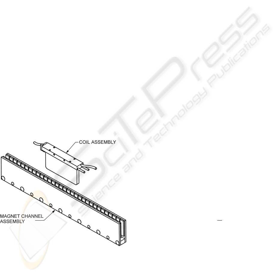
The motors considered here are PM LSM with epoxy
cores. A PM LSM consists of a secondary and a mov-
ing primary. There are two basic classifications of PM
LSMs: epoxy core (i.e. non-ferrous, slotless) and iron
core. Epoxy core motors have coils wound within
epoxy support. These motors have a closed mag-
netic path through the gap since two magnetic plates
”sandwich” the coil assembly (Anorad, 1999). Fig-
ure 1 shows an unmounted PM LSM with epoxy core.
The secondary induces a multipole magnetic field in
Figure 1: Anorad LE linear motor
the air gap between the magnetic plates. The mag-
net assembly consists of rare earth magnets, mounted
in alternate polarity on the steel plates. The elec-
tromagnetic thrust force is produced by the interac-
tion between the permanent magnetic field in the sec-
ondary and the magnetic field in the primary driven by
the phase currents of the servo amplifier. The linear
motor under evaluation is a current-controlled three-
phase motor driving a carriage supported by roller
bearings. The motor drives a mass of total 1.5 Kg
and is vertically mounted.
2.2 Servo Amplifier
The servo amplifiers employed in the setup are PWM
types with closed current control loop. The software
commutation of the three phases is performed in the
motion controller with the help of the position en-
coder. This commutation method requires two current
command signals, from the controller. The initializa-
tion routine for determining the phase relationship is
part of the motion controller. The third phase current
depends on the others, because of the star connection.
i
C
= −i
A
− i
B
(1)
The maximum input signals u
A
, u
B
of the servo
amplifier (±10V ) correlate to the peak currents of the
current loops. In the setup the peak current of the
amplifier is 25A. The PWM works with a switching
frequency of 24kHz. The current loop bandwidth is
specified with 2.5kHz. (Anorad, 1998)
3 SYSTEM MODELING
The thrust force is produced by interaction between
the permanent magnetic field in the secondary and
the electromagnetic field of the phase windings. The
thrust force is proportional to the magnetic field and
the phase currents i
A
, i
B
, i
C
. The back-EMF (elec-
tromotive force) induced in a phase winding (e
A
, e
B
,
e
C
) is proportional to the magnetic field and the speed
of the motor. The total thrust force F
thrust
is the sum
of the forces produced by each phases:
˙xF
thrust
=
p
e
p
(x) i
p
; p ∈{A, B, C} (2)
The back-EMF waveforms
e
p
˙x
can also be inter-
preted as the force functions of the phases (K
M
p
(x)).
F
thrust
=
p
K
M
p
(x) i
p
; p ∈{A, B, C} (3)
There are two types of position dependent distur-
bances: cogging force and force ripple. Cogging is a
magnetic disturbance force that is caused by attraction
between the PMs and the iron part of the primary. The
force depends on the relative position of the primary
with respect to the magnets, and it is independent of
the motor current. Cogging is negligible in motors
with iron-less primaries (Anorad, 1999).
ICINCO 2004 - INTELLIGENT CONTROL SYSTEMS AND OPTIMIZATION
34

Force ripple is an electro-magnetic effect and
causes a periodic variation of the force constant.
There are two physical phenomena which lead to
force ripple: Reluctance force and harmonics in the
electromagnetic force. Reluctance force occurs only
in motors with interior mounted PMs. In this type of
motor the reluctance of the motor is a function of the
position. The self inductance of the phase windings
varies with the position of the primary with respect to
the secondary. When current flows, this causes a posi-
tion dependent force. If the PMs are surface mounted,
the reluctance is constant and reluctance force is neg-
ligible.
In ironless and slotless motors the only source
of force ripple are harmonics in the electromagnetic
force. Only if the back-EMF waveforms are sinu-
soidal and balanced, symmetric sinusoidal commu-
tation of the phase currents produces smooth force.
Force ripple occurs if the motor current is different
from zero, and its absolute value depends on the re-
quired thrust force and the relative position of the pri-
mary with respect to the secondary.
There are several sources of force ripple:
• motor
– harmonics of back-EMFs
– amplitude imbalance of back-EMFs
– phase imbalance of back-EMFs
• amplifier
– offset currents
– imbalance of current gains
Offset currents lead to force ripple with the same
period as the commutation period. This force ripple
is independent of the desired thrust force. Amplitude
or phase imbalance of the motor and imbalance of
amplifier gains lead to force ripple with half commu-
tation period which scale in direct proportion to the
desired thrust force. A k
th
order harmonic of a back-
EMF produces (k−1)
th
and (k+1)
th
order harmonic
force ripple if sinusoidal currents are applied.
Force ripple with the same period as the commuta-
tion period is independent of the desired current, all
higher order harmonics scale in direct proportion to
the desired current because of the linearity of the force
equation (2).
4 OPTIMIZATION OF CURRENT
EXCITATION
The method for optimization of current excitation
consist of three stages. In every stage different har-
monics of the force ripple spectrum are reduced. In
order to optimize the waveforms of the currents, iden-
tification of the force functions K
M
p
(x) is essential.
The main idea of the proposed method is to identify
the force functions in a closed position control loop by
measuring the force command signal u of the position
controller at constant load force F
load
as a function of
the position x. Neither additional sensor nor device
for position adjustment are necessary. In the exper-
imental setup the constant load force is produced by
the force of gravitation. In order to avoid inaccuracy
by stiction the measurement is achieved with moving
carriage. The position of the carriage is obtained from
an incremental linear optical encoder with a measure-
ment resolution of 0.1µm.
4.1 Experimental Analysis of Force
Ripple
In order to analyze the force ripple of the motor a si-
nusoidal reference current is applied:
u
A
(u, ϑ)=u
2
3
sin (ϑ(x)) + o
A
(4)
u
B
(u, ϑ)=u
2
3
sin
ϑ(x)+
2 π
3
+ o
B
with ϑ(x)=
π
τ
p
(x − x
0
)
where u
A
, u
B
are the current commands of the
two phases, u is the output of the position controller
(force command), x is the position of the carriage, τ
p
is the pole pitch and x
0
is the zero position with max-
imum force. In the first stage, the DC components of
the command signals (o
A
, o
B
) are chosen equal zero.
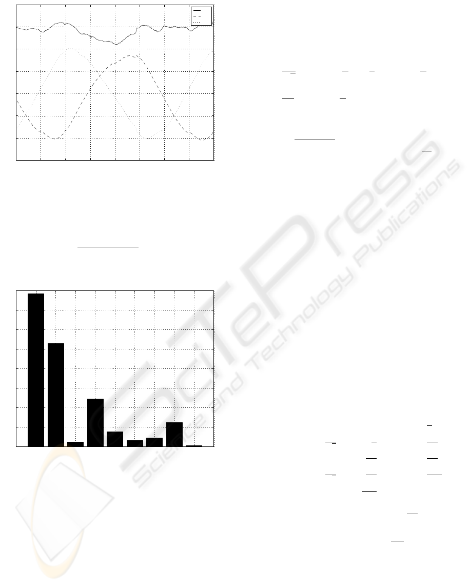
Figure 2 shows the control signals u, u
A
, u
B
versus
the position x. The ripple on the force command sig-
nal u is caused by force ripple. The controller com-
pensates the force ripple by changing the force com-
mand signal over the position. If the speed of the mo-
tor is high, the force ripple increases the tracking er-
ror.
Frequency domain analyses of the force command
indicates that the fundamental corresponds to the
commutation period 2 τ
p
. In order to estimate the pa-
rameters of the ripple a least square estimation of the
model parameters (5) was applied. A least square es-
timation is chosen, because noise overlays the force
command signal.
f(x, θ)=θ
1
+ θ
2
x +
N
k=1
θ
2k+1
sin
kπ
x
τ
p
(5)
+θ
2k+2
cos
kπ
x
τ
p
where θ
k
are the estimated parameters. With θ
1
the
sum of load force and friction is estimated. The mod-
eled spring force (θ
2
) is necessary, because the force
OPTIMIZATION OF CURRENT EXCITATION FOR PERMANENT MAGNET LINEAR SYNCHRONOUS MOTORS
35
−25 −20 −15 −10 −5 0 5 10 1
5
−1.5
−1
−0.5
0
0.5
1
1.5
2
x [mm]
u [V]
u
u
A
u
B
Figure 2: Phase currents at load force F
load
=20N
command signal rises with rising positions. This is
caused by wire chains. Figure 3 shows the amplitudes
of the sinusoids
θ
2
2k+1
+ θ
2
2k+2
versus the order of
the harmonics k.
0 1 2 3 4 5 6 7 8 9 10
0
0.02
0.04
0.06
0.08
0.1
0.12
0.14
0.16
k
Amplitude
Figure 3: Spectrum of the force command
The fundamental period (k =1) corresponds to
2 τ
p
(30mm). The amplitude of this sinusoid is inde-
pendent of the load force. The higher order harmonics
(k>1) scale in direct proportion to the load force be-
cause of the linearity of the force equation (3).
4.2 Compensation of Command
Independent Force Ripple
The curve of the phase current command u
A
in figure
2 shows that this command independent ripple pro-
duces a DC component of the current command. This
DC component compensates offsets in the analog cir-
cuits of the servo amplifier. In the first stage the DC
components of the phase current commands are cal-
culated and applied in (4) as
o
A
=
a
√
3
cos
α −
π
6
−
a
3
sin
α −
π
6
(6)
o
B
=
2 a
3
sin
α −
π
6
where
a =
θ
3
2
+ θ
4
2
and α = arctan
θ
4
θ
3
.
In an servo system with iron-less motor the DC
components compensate the offsets of the amplifier.
If an iron motor is employed, the DC components
generate a sinusoidal force which compensates the
cogging force.
4.3 Identification of Force Functions
In the next stage the force functions of the phases
are identified. In order to optimize the current wave-
forms, it is essential to identify the amplitudes and
phases of the force functions properly. The motor effi-
ciency depends directly on a properly identified com-
mutation zero position x
0
which depends on the phase
lag of the force functions. In (R
¨
ohrig and Jochheim,
2002) a sinusoidal commutation is applied to identify
the force functions. By means of sinusoidal commu-
tation it is impossible to identify the force functions
idenpendently. In this paper a square-wave commuta-
tion is applied, in order to identify the force functions
independently:
u
A
(u, ϑ)=
⎧
⎪
⎪
⎪
⎪
⎪
⎪
⎨
⎪
⎪
⎪
⎪
⎪
⎪
⎩
0: 0≤ ϑ<
π
6
u
√
3
:
π
6
≤ ϑ<
5 π
6
0:
5 π
6
≤ ϑ<
7 π
6
−
u
√
3
:
7 π
6
≤ ϑ<
11 π
6
0:
11 π
6
≤ ϑ<2 π
(7)
The second phase command signal is
2 π
3
apart:
u
B
(u, ϑ)=u
A
u, ϑ +
2 π
3
(8)
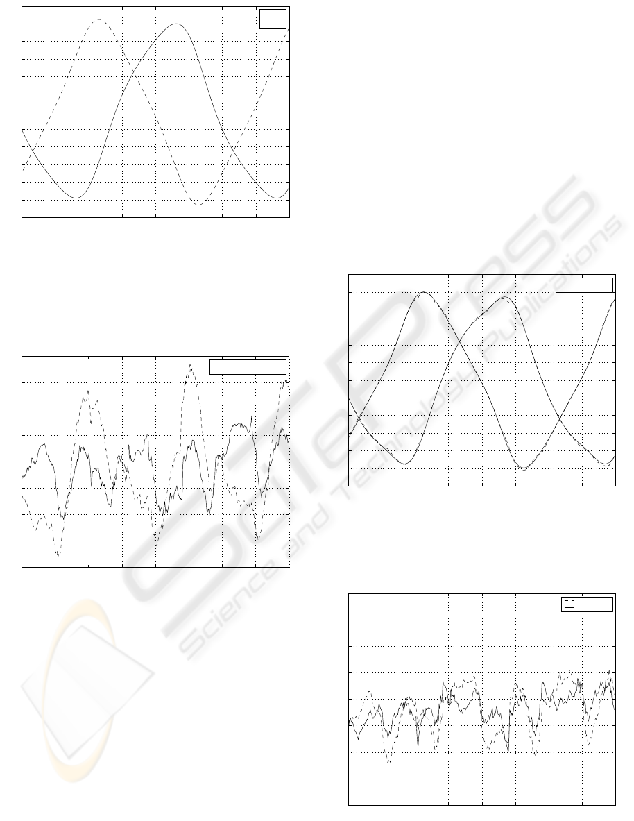
Figure 4 shows the phase currents i
A
, i
B
, i
C
versus
the position x, when square-wave commutation is ap-
plied. The minimum values of the phase currents cor-
relate to the maximum values of the force functions.
In square-wave commutation always two phases share
the same absolute value of current, which depends on
the force command u and the current gains of the am-
plifier K
S
p
.
ICINCO 2004 - INTELLIGENT CONTROL SYSTEMS AND OPTIMIZATION
36

−25 −20 −15 −10 −5 0 5 10 1
5
−3
−2
−1
0
1
2
3
x [mm]
i
A
, i
B
, i
C
[A]
i
A
i
B
i
C
Figure 4: square-wave commutation
|i
p
| = K
S
p
u
√
3
; p ∈{A, B} (9)
Since only two phase currents are independent, the
force equation can be described as:
F
thrust
= K
A
(ϑ) u
A
+ K
B
(ϑ) u
B
(10)
where K
A
(ϑ) and K
B
(ϑ) are the force functions
of the current commands u
A
and u
B
respectively.
√
3 F
thrust
u(ϑ)
=
⎧
⎪
⎪
⎪
⎪
⎪
⎨
⎪
⎪
⎪
⎪
⎪
⎩
K
B
(ϑ):−
π
6
≤ ϑ<
π
6
K
A
(ϑ):
π
6
≤ ϑ<
π
2
−K
B
(ϑ):
5 π
6
≤ ϑ<
7 π
6
−K
A
(ϑ):
7 π
6
≤ ϑ<
9 π
6
(11)
Figure 5 shows the identified force functions. Sinu-
soids are applied to approximate the force functions,
because the back-EMFs of the motor are nearly sinu-
soidal.
4.4 Current Waveform Optimization
Aim of the current waveform optimization is to ob-
tain reference waveforms of the phase currents which
generate smooth force. Inspection of the force
equation(10) reveals that there are an infinite num-
ber of waveforms that generates smooth force. There-
fore a secondary condition has to be applied . Since
one problem of epoxy-core PM LSM is overheating,
the logical choice is to minimize the winding losses.
The problem is formulated as constrained optimiza-
tion. The constraint of the optimization is a position
independent force
−25 −20 −15 −10 −5 0 5 10 1
5
−15
−10
−5
0
5
10
15
x [mm]
k
A
, k
B
[N / V]
k
A
k
B
Figure 5: Identified force functions
F
thrust
= K
A
(ϑ) u
A
+ K
B
(ϑ) u
B
= K
F
u = f(ϑ)
(12)
where K
F
is a freely eligible constant and u is the
force command. The winding losses can be written as
P
cu
(x)=
p
R
p
i
2
p
(x); p ∈{A, B, C} (13)
where R
p
is the resistance of phasewinding p.In
assumption of symmetric winding resistances R
A
=
R
B
= R
C
and servo amplifier gains K
S
A
= K
S
B
the
functional to be minimized can be written
f(u
A
,u
B
)=u
2
A
+ u
2
B
+ u
A
u
B
. (14)
If the resistances are unsymmetric and/or the gains
are unequal and known, (14) has to be adapted to meet
the requirements. In case of small unsymmetric resis-
tances and gains, the minimization of (14) minimizes
the winding losses approximately. After substituting
(12) in (14) the optimized waveforms can be obtained
by minimizing (14)
u
A
=
∂f(u
A
,u
B
)
∂u
A
=0 (15)
u
B
=
∂f(u
B
,u
B
)
∂u
B
=0
as
u
A
(u, ϑ)=
K
A
(ϑ) −
1
2
K
B
(ϑ)
K
2
A
(ϑ)+K
2
B
(ϑ) − K
A
(ϑ) K
B
(ϑ)
K
F
u
(16)
u
B
(u, ϑ)=
K
B
(ϑ) −
1
2
K
A
(ϑ)
K
2
A
(ϑ)+K
2
B
(ϑ) − K
A
(ϑ) K
B
(ϑ)
K
F
u.
OPTIMIZATION OF CURRENT EXCITATION FOR PERMANENT MAGNET LINEAR SYNCHRONOUS MOTORS
37
−25 −20 −15 −10 −5 0 5 10 1
5
−1
−0.8
−0.6
−0.4
−0.2
0
0.2
0.4
0.6
0.8
1
x [mm]
u
A
, u
B
u
A
u
B
Figure 6: Optimized waveforms
In Figure 6 the optimized phase current waveforms
are shown. Figure 7 compares the ripple of the force
−25 −20 −15 −10 −5 0 5 10 1
5
1.2
1.25
1.3
1.35
1.4
1.45
1.5
1.55
1.6
x [mm]
u [V]
sinusoidal waveforms
optimized waveforms
Figure 7: Force command signals with sinusoidal versus
optimized waveforms
commands by use of different commutation functions.
The dashed line shows the force command when a
sinusoidal commutation plus offset compensation is
employed (4). The solid line shows the force com-
mand when optimized waveforms are applied. The
ripple of the force command is significantly reduced
when the optimized waveforms are applied. The op-
timized waveforms maximize the motor efficiency by
minimizing the ohmic winding losses.
4.5 Fine tuning of waveforms
After optimization of the waveforms the motor effi-
ciency is maximized, but the force command still con-
sists of some higher order ripple. The higher order
ripple is caused by unmodeled harmonics of the force
functions. In order to reduce some of the higher order
ripple a fine tuning of the waveforms is performed.
The main idea of the fine tuning algorithm is to mea-
sure the phase current control signals at constant load
force. The fine tuning is performed with previously
optimized waveforms in order to maximize motor ef-
ficiency. The still remaining higher order ripple of the
force command modulates the optimized waveforms.
The fine tuning algorithm approximates the shapes
of the measured phase command signals with Fourier
series. Figure 8 compares the measured phase com-
mand signals with the approximation. Figure 9 com-
pares the commutation functions of the second stage
with the third stage.
−25 −20 −15 −10 −5 0 5 10 1
5
−1
−0.8
−0.6
−0.4
−0.2
0
0.2
0.4
0.6
0.8
1
x [mm]
u
A
, u
B
[V]
measurement
approximation
Figure 8: Fine Tuned Waveforms
−25 −20 −15 −10 −5 0 5 10 15
1.2
1.25
1.3
1.35
1.4
1.45
1.5
1.55
1.6
x [mm]
u [V]
optimization
fine tuning
Figure 9: Force command signals with optimized versus
fine tuned waveforms
ICINCO 2004 - INTELLIGENT CONTROL SYSTEMS AND OPTIMIZATION
38
u
A
(u, ϑ)=u
2
3
sin(ϑ)+a
3
sin(3 ϑ + α
3
)+
(17)
a
5
sin(5 ϑ + α
5
)
+ o
A
u
B
(u, ϑ)=u
2
3
sin
ϑ +
2 π
3
+ b
3
sin(3 ϑ + β
3
)+
b
5
sin(5 ϑ + β
5
)
+ o
B
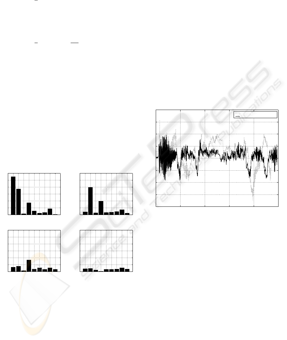
Figure 10 compares the command signal spectrum
of the optimization process. The upper left graph
shows the spectrum before any optimization is ap-
plied. The upper right graph shows the spectrum after
the offset compensation is applied. The fundamen-
tal is significantly reduced. In the lower left graph
the spectrum of the force command of the optimized
waveforms is shown. This stage reduces the 2
th
order
harmonics. The lower right graph shows the spectrum
of the force command for fine tuned waveforms. This
last stage reduces the 2
th
and 4
th
order harmonics.
After the fine tuning of the waveforms no dominant
harmonic exists in the force command.
1 2 3 4 5 6 7 8 9
0
2
4
6
8
10
12
Without Optimization
Amplitude [%]
1 2 3 4 5 6 7 8 9
0
2
4
6
8
10
12
Step 1
Amplitude [%]
1 2 3 4 5 6 7 8 9
0
2
4
6
8
10
12
Step 2
Amplitude [%]
1 2 3 4 5 6 7 8 9
0
2
4
6
8
10
12
Step 3
Amplitude [%]
Figure 10: Spectrum of force command signals
5 Controller Design
Figure 11 shows the block diagram of the servo con-
trol system. In order to achieve a better tracking per-
formance, a feedforward controller is applied. Feed-
back control without feedforward control always in-
troduces a phase lag in the command response. Feed-
forward control sends an additional output, besides
the feedback output, to drive the servo amplifier input
to desired thrust force. The feedforward control com-
pensates the effect of the carriage mass and the fric-
tion force. The friction force is modeled by a kinetic
friction model and identified with experiments at dif-
ferent velocities. The mass of the carriage is identified
with a dynamic least square algorithm. The stability
of the system is determined by the feedback loop. The
compensation of the force ripple is completely per-
formed in the waveform generator with Fourier series
approximation. Figure 12 compares the tracking er-
ror of a movement without ripple compensation with
the movement with ripple compensation. In this mea-
surement, the carriage moves from position −25mm
to position 15mm and back to position −25mm with
v
max
= 200mm/s. If the ripple compensation is ap-
plied, the tracking error is reduced significantly.
0 0.1 0.2 0.3 0.4 0.
5
−8
−6
−4
−2
0
2
4
6
8
t [s]
e [µm]
with sinusoidal commutation
with waveform optimization
Figure 12: Tracking error
6 CONCLUSION
In this paper, a method for optimization of the current
waveforms for PM LSMs is presented. The optimized
waveforms generate smooth force and produce mini-
mal copper losses which maximizes motor efficiency.
The optimized current shapes are valid for any veloc-
ity and any desired thrust force. Since the waveforms
can be easily adapted to any shape of the back-EMF,
motor design can be focused on increasing the mean
force of the motor and reducing the cost of produc-
tion. Experiments show that the tracking performance
is significantly improved if the optimized waveforms
are applied. The described optimization method is
implemented successfully in the motion controllers of
several machines for semiconductor production to im-
prove the tracking performance.
OPTIMIZATION OF CURRENT EXCITATION FOR PERMANENT MAGNET LINEAR SYNCHRONOUS MOTORS
39

Currents
P hase Current
C om m ands
x
Position
Feedback
C ontrol
Waveform
G enerator
Reference
Position
x
ref
Servo
Am plifier
Linear
Motor
Feedforward
C ontrol
u
fb
u
ff
e
u
B
u
A
i
A
i
B
i
C
Figure 11: Controller design
REFERENCES
Anorad (1998). High Voltage Brushless D.C. Servo Ampli-
fier, Hardware Maintenance Manual. Anorad Corpo-
ration.
Anorad (1999). LE Series Linear Motor Systems, Motor
Integration Manual LEA, LEB, LEC & LEM Linear
Motors. Anorad Corporation.
Basak, A. (1996). Permanent-Magnet DC Linear Motors.
Clarendon Press, Oxford.
Cassat, A., Corsi, N., Moser, R., and Wavre, N. (2003). Di-
rect Linear Drives: Market and Performance Status.
In Proceedings of the 4th International Symposium on
Linear Drives for Industry Applications, pages 1–11,
Birmingham, UK.
Gieras, J. and Zbigniew, J. (1999). Linear Synchronous Mo-
tors: Transportation and Automation Systems. CRC
Press, Boca Raton.
Jahns, T. M. and Soong, W. L. (1996). Pulsating Torque
Minimization Techniques for Permanent Magnet AC
Motor Drives - A Review. IEEE Transactions on In-
dustrial Electronics, 43(2):321–330.
Lee, T., Tan, K., Lim, S., and Dou, H. (2000). Iterative
Learning of Permanent Magnet Linear Motor with Re-
lay Automatic Tuning. Mechatronic, 10(1-2):169–
190.
Lin, F., Lin, C., and Hong, C. (2000). Robust Control of
Linear Synchronous Motor Servodrive Using Distur-
bance Observer and Recurrent Neural Network Com-
pensator. IEE Proceedings Electric Power Applica-
tions, 147(4):263–272.
Otten, G., de Vries, T., van Amerongen, J., Rankers, A., and
Gaal, E. (1997). Linear Motor Motion Control Using a
Learning Feedforward Controller. IEEE/ASME Trans-
actions on Mechatronics, 2(3):179–187.
R
¨
ohrig, C. and Jochheim, A. (2001). Identification and
Compensation of Force Ripple in Linear Permanent
Magnet Motors. In Proceedings of the American Con-
trol Conference 2001, pages 2161–2166, Arlington,
USA.
R
¨
ohrig, C. and Jochheim, A. (2002). Motion Control of
Linear Synchronous Motors with Force Ripple Com-
pensation using Current Shaping. In Proceedings of
the 15th IFAC World Congress on Automatic Control,
Barcelona, Spanien.
Schrijver, E. and van Dijk, J. (1999). H
∞
Design of Distur-
bance Compensators for Cogging Forces in a Linear
Permanent Magnet Motor. Journal A, 40(4):36–41.
Seguritan, A. and Rotunno, M. (2002). Adaptive Torque
Pulsation Compensation for a High-torque DC Brush-
less Permanent Magnet Motor. In Proceedings of
the 15th IFAC World Congress on Automatic Control,
Barcelona, Spanien.
Van den Braembussche, P., Swevers, J., and Van Brussel,
H. (1998). Linear Motor Ripple Compensation Using
Position-triggered Repetitive Control. In Proceedings
of the IFAC Workshop on Motion Control, pages 353–
357, Grenoble, Frankreich.
Van den Braembussche, P., Swevers, J., Van Brussel, H.,
and Vanherck, P. (1996). Accurate Tracking Control
of Linear Synchronous Motor Machine Tool Axes.
Mechatronics, 6(5):507–521.
Xu, L. and Yao, B. (2000). Adaptive Robust Precision Mo-
tion Control of Linear Motors with Ripple Force Com-
pensations: Theory and Experiments. In Proceed-
ings of the IEEE Conference on Control Applications,
pages 373–378, Anchorage, USA.
ICINCO 2004 - INTELLIGENT CONTROL SYSTEMS AND OPTIMIZATION
40
