
Remote Laboratory for Industrial Automation
Rui Delgado
1
, Gustavo Santos
1
, Carlos Cardeira
1
, J. R. C. Pinto
1
, Rui Loureiro
2
,
Otto Leichsenring
3
1
Lisbon Technical University, Instituto Superior Técnico, GCAR – DEM, 1049-001 Lisboa
2
GOM, 1500-371 Lisboa
3
Infocontrol - Electrónica e Automatismos, 2745-740 Massamá
Abstract.
In this paper we present a remotely accessed experiment on
industrial automation. Using this remote access, students may verify the
correctness of their previous work and increase the productivity of laboratory
classes. The experiment provides a web page for interfacing with a
Programmable Logic Controller (PLC) which controls an electro-pneumatic
process. Students may remotely download the program to the PLC and access
to the PLC states and variables remotely, allowing the detection of semantic
errors. Moreover a Webcam shows the image of the process which, not being
essential, provides a more realistic view of the program correctness. The user
has access to the system inputs through a web based Human-Machine Interface
(HMI). This paper results from collaboration between a PLC solution provider
and the university.
1 Introduction
In engineering, good practice is the key to an efficient learning. However in academic
environments sometimes the physical resources and the time available for access to
equipment are not enough. Students usually have a few hours of weekly access to
their laboratory equipments to perform their experiments. Even if they correctly do
their home work something can go wrong during the laboratory access time and ruin
the process.
The worldwide spread of the I
n
ternet and its general acceptance has brought new
opportunities in distance learning as well in traditional learning [2]. Consequently the
concepts of virtual and remote laboratories appear. The first ones use software
simulation of physical devices. The second ones provide remote access to real
laboratory equipment and instruments [1].
As in [1] the common principle of remote laboratory experimentations is that learners
can cha
n
ge system parameters through Internet. Then a special interface converts
those parameters to comprehensible and acceptable data for the local equipments.
These have many advantages as:
Delgado R., Santos G., Cardeira C., R. C. Pinto J., Loureiro R. and Leichsenring O. (2004).
Remote Laboratory for Industrial Automation.
In Proceedings of the First International Workshop on e-Learning and Virtual and Remote Laboratories, pages 28-37
DOI: 10.5220/0001150800280037
Copyright
c
SciTePress

Resource sharing becomes a reality, improving the utilization of costly equipment [2].
Increase of test time in academic environments.
Reduction of class excessive congestion.
We focus that previous simulation is an excellent tool for increasing the productivity
during automation lab sessions. In the automation field, tools like Automation Studio
provide an effective way for students simulate their circuits (pneumatic, electrical or
hydraulic) and to test if the PLC program (Ladder Diagrams or Sequential Flow
Charts) do behave like expected. This previous work of simulation highly increases
the productivity of laboratory sessions. Even without access to such tools, students
may use simple programs made on standard languages to test the correctness of their
logical expressions.
But even using simulation software tools, they are not able to generate code to all the
PLC brands. Some brands are already covered, but in many cases it is still mandatory
to make use of the software tools provided by the PLC manufacturer.
Hence, even if the PLC manufacturer provides free programming software for all the
students, students are only able to detect syntax errors. Existing semantic may only be
detected with a connection to a PLC. It becomes very useful to provide a remote
accessed PLC letting students download their code to the remote PLC, allowing the
detection and correction of semantic errors. Moreover, a web interface for the remote
lab provides the student the ability to simulate inputs activation of the PLC as well as
other useful information for the system state variables. This remote laboratory was
idealized to be used by students of classes of automation and control for their
laboratory class works elaboration.
2 State of the Art
The use of virtual laboratories or remote laboratories are current practices for
increasing the productivity of laboratory courses.
Remote laboratories for automation provide students a full day long access to the
laboratory equipment (24 hours a day and 7 days a week), letting them have time to
correct almost all sorts of errors on their programs.
In our days Internet can easily be a remote gateway to the physical laboratory. It can
be used to remotely provide the realism of local environments [1], where users can
plan and conduct experiments, collect experimental data, and analyse the results as if
they were physically present in the laboratory [2].
This is an area being explored in actual scientific researches, and some solution are
presented using software simulation as Mathworks/Matlab+Simulink [5] or National
Instruments Labview [4] . Other approaches exist [1] [6] using JAVA technologies.
This work regards a remote laboratory for automation. It introduces an approach for a
remote laboratory using SAIA software and hardware, which also allows, easily, the
conception of HMI (Human-Machine Interface) using HTML and Javascript, visible
at any web browser, with a certain level of security in the remote access of these
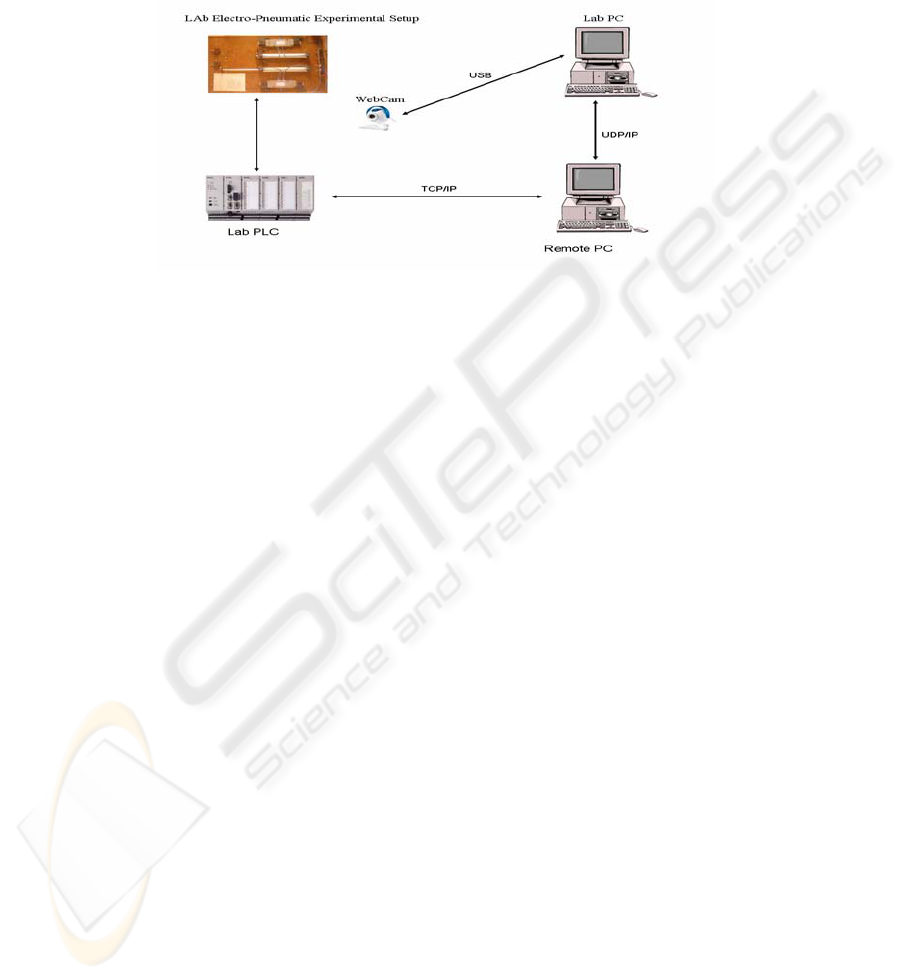
interfaces (Fig.1).
27
3 Proposed Solution
A remote laboratory has two distinct elements: the physical laboratory equipment, and
the remote PC that controls and supervisions it.
Fig. 1. System architecture.
In our system the laboratory equipment consists of SAIA-BURGESS PCD4.M170
PLC, where previously programmed routines, should be downloaded and tested. This
PLC can have connected other equipments as electro-pneumatic experimental setups,
energetic analysers, access control readers, etc.
This PLC has integrated a Web Server, which supports the allocation of HTML files
and communicates with remote PCs, via a TCP/IP protocol. For this effect the PLC
has incorporated an Ethernet RJ45 Connector.
Using the specific SAIA PG5 application in the remote Personal Computer (PC), any
user can connect, download, test and debug remotely his programmed routines as if he
was on site. The remote PC can also run a specific Web Server (SAIA Web-Connect)
which allows the access of the HTML pages allocated in the PLC at any Web browser
to anyone with permission. In this way HMI can easily be conceived and accessed to
remotely control and monitor the PLC using the widely spread acknowledgement of
HTML and Javascript languages. In order to provide a live view of what is happening
in the laboratory a Webcam is used connected via USB to a local PC.
For the video communication between the Lab PC and the remote PC a typical
internet live video conference application can be used. Any user simply connects
remotely to the Lab PC and watches what’s happening in the laboratory.
3.1 Communication PLC-Remote PC
The communication between the PLC and the PC running the Web Server can be
made using TCP/IP, S-BUS or PGU. The last two modes are specific for SAIA PLCs.
They use a RS232 connection and the communication and respective configuration is
made with the Web Server provided by SAIA-BURGESS (SAIA Web-Connect)
which is installed in the PC [11]. Since the PC is located remotely the implemented
28

solution was made through TCP/IP. SAIA-Burgess Web Server functions are split:
The PLC has the responsibility to do the file administration while the PC running the
Web Server handles the requests from TCP/IP communications used to call control
and monitoring functions. It is then possible to communicate between the PC and
PLC using a simple, efficient protocol that uses fewer resources than TCP/IP.
Reduced to the transfer function, this protocol does not affect the real-time behaviour
of the PLC. Standard browsers, like Microsoft Internet Explorer or Mozilla, make file
requests to the Web Server using the TCP/IP protocol. To enable communication with
the Web Server in the PLC, the Web-Connect software must be installed on a PC,
which works as the communication part of the Web Server. Web-Connect receives
those requests from the browser using the TCP/IP protocol and forwards them with an
efficient protocol from the PC to the PLC. This is made using one of the possible
communication modes previously configured. PLC answers are converted back into
TCP/IP and sent to the browser. Some advantages of this Web Server are: Simple and
low-cost creation of control and monitoring interfaces (HMI) with familiar HTML
editors, such as Frontpage or Dreamweaver; Control and Monitoring of the system
accessing the interface with commonly used web browsers, like Microsoft Internet
Explorer or Mozilla.
The configuration is made using a setup page pre-built in the Web Server accessed
with a common web browser at a location http://<pc-ip-address>/setup. After the
station configuration the web interface can be accessed at a location http://<pc-ip-
address>/<station-name>.
3.2.1 HTML Server
The HTML Server is the core of the Web Server. Its function is sending HTML pages
requested by the web browser (as well as images) across the S-BUS Driver to the PC.
HTML pages or images are stored in the user files memory of the PLC, which were
previously downloaded to it, along with the remaining program.
The HTML server also checks HTML pages for possible existing Process Data Point
(PDP) identification key.
When the HTML Server finds a PDP key in a HTML page, sends it to the Data Server
which transfers them in the requested PLC data from the PLC’s memory back to the
HTML Server.
PDP keys are embedded in the HTML code, being used for addressing PLC data.
Below are some examples of these keys application:
%%PDP,,I16,B% addressing one input “I16” and format is binary.
%%PDP,,R300,F% addressing the register 300, format is in floating point.
%%PDP,,DB10.20,d% addressing Data Block 10, element 20, format is decimal.
More detailed information about the Web Server and its individual elements can be
seen in [7].
3.3 Examples
The system described in this article can be used by students to develop possible
solutions to problems presented to them in lessons such as the ones below:
29

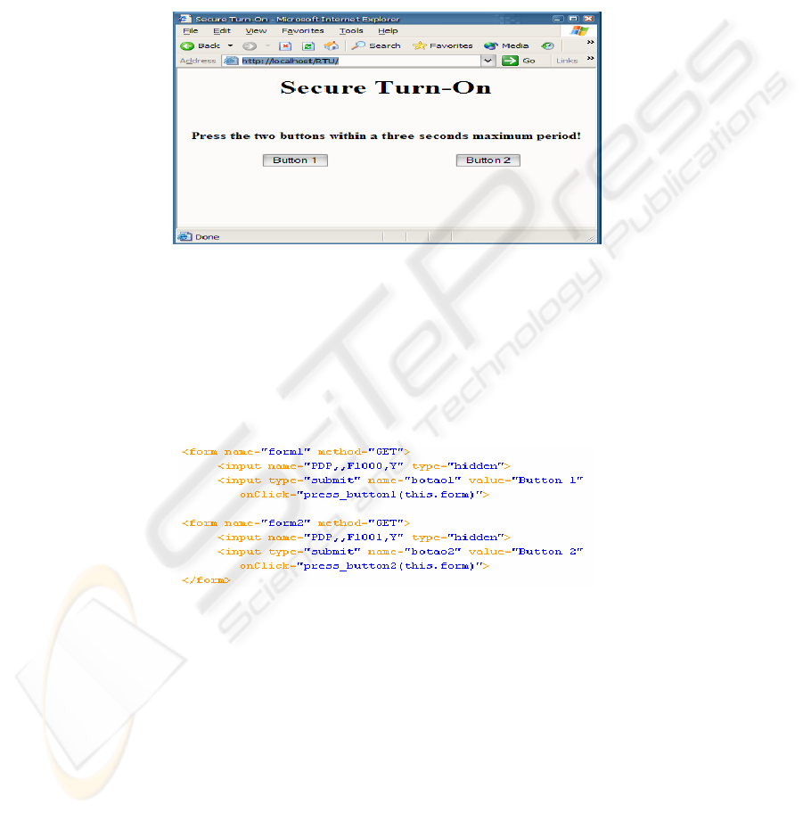
3.3.1 First problem: Secure Turn-On
“When machines operation may wound operators, a safety measure consists in
requiring that the machine only starts when two switches are pressed, to force the
operator to use both hands, improving his security conditions. A commonly used trick
used by irresponsible operators consists in using something to keep one the buttons
pressed (like a matchstick), and using only the other button, keeping the other hand
free. To prevent this, develop a program that only activates the cylinder when the two
buttons are pressed within a three seconds maximum delay.”
3.3.2 Second problem: E-commerce orders dispatching
“In an online store, after a client selects the product he wants to buy, he selects the
amount of the product to dispatch. That store has a dispatch warehouse which
receives that amount and immediately processes it through a packaging circuit that
packs the order to the client.”
To simulate this environments an electro-pneumatic setup was used in the laboratory.
It is composed by two pneumatic cylinders, each controlled by double-acted electrical
controlled pneumatic directional valve (5/2). To read each cylinder position there are
two toggle switches, normally open. The first cylinder simulates the filling of the
package with the selected amount of the product, while the second cylinder closes and
pushes the order out of the circuit to be shipped. It is pretended that the students
execute the cycle using the knowledge they acquire in lessons, like programming
routines to read inputs, set outputs and use counters and timers.
4 Developments
To develop the solution to the problem described above, it is necessary to create the
project using PG5, creating the source and Graftec files. Graftec is the name for the
SAIA implementation of IEC 61131-3 Sequential Function Charts which is much
closed to Grafcet). The necessary routines to control the PLC’s inputs and outputs are
developed in these files.
To make the button pressing simulation via web it’s necessary to add a Web-Server
project file, so that web pages can be added, after created.
Web pages are created using standard html editors and embedding PDP keys in them,
to access PLC data, as described previously. In this particular case, sample web pages
supplied with Web-Connect were used, with some minor modifications, to simulate
the pressing of the two buttons required in the problem. These web pages have to be
placed in the “html” subfolder of the created PG5 project so they can be added and
processed by the Web-Builder.
After the creation of the necessary files and their compilation, the project can be
downloaded to the PLC. This is done through the PG5, after configuring the IP
address of the PLC and password, if necessary.
30
4.1 Solution to the first problem
The first step was to create the Graftec routine that perform the realized task in the
SAIA PG5 application.
After the SAIA-Graftec conception a simple HTML interface was conceived (Fig. 2)
at any HTML editor.
The press of a button is represented in the PLC by a flag set. The HTML code
consists in a form for each button (Fig. 3).
Fig. 2. HTML interface.
Each form has two inputs: one that corresponds to the physical button that appears in
the web browser and other which is a hidden field with the PDP key to the
correspondent flag in it. When a button is clicked in the web page a Javascript
function is called that sets the element of the hidden field, corresponding to the PLC
flag, by the process described in section 3.1.1.
Fig. 3. HTML interface code.
If the two buttons are pressed within 3 seconds, each corresponding flag is set in this
period and the Grafcet routine running in the PLC sets the cylinder output.
After all the programming realized the HTML file was added to the Web Server
project file, the Graftec and source files were build and the resulting program was
downloaded to the PLC memory. All these can be done in the PG5.
Next the user can go online with the PLC via the SAIA Online Debug (Fig. 4), to
remotely test and debug the conceived routines. If these are working correctly the user
31
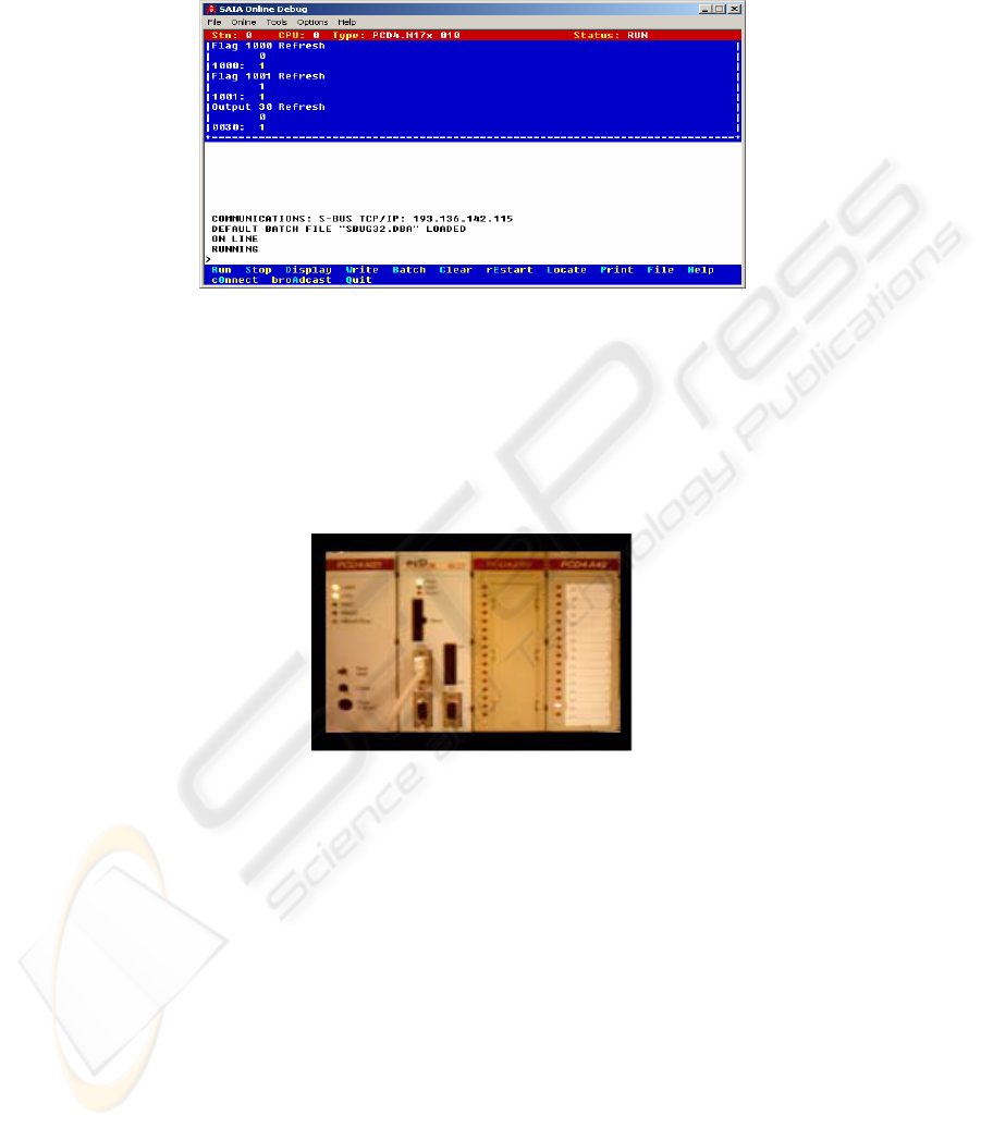
can access the HTML interface conceived at any web browser, after the Web-Connect
being launched.
Fig. 4. Online Debug.
In order to have a more realistic experience an internet live video conference
application can be launched and after established the connection with the Lab PC,
with the Webcam connected, the user can have a real-time view of what’s happening
in the laboratory (Fig. 5). If the two buttons are pressed within the right period in the
remote web browser the results in the laboratory can be remotely seen.
Fig. 5. Remote live view of the Lab PLC.
4.2 Solution to the second problem
In the first place the SAIA-Graftec routine was created (Fig. 6). A start flag launches
the routine. Then an output is set that actuates the first cylinder (via the respective
electro-pneumatic valve). After its position detected by the actuated toggle switch the
cylinder retracts. This cycle is repeated as many times as the value of a counter (with
the size of the order to dispatch). Next a second cylinder is actuated and stays in this
position for 3 seconds (using a timer), after which it retracts.
32
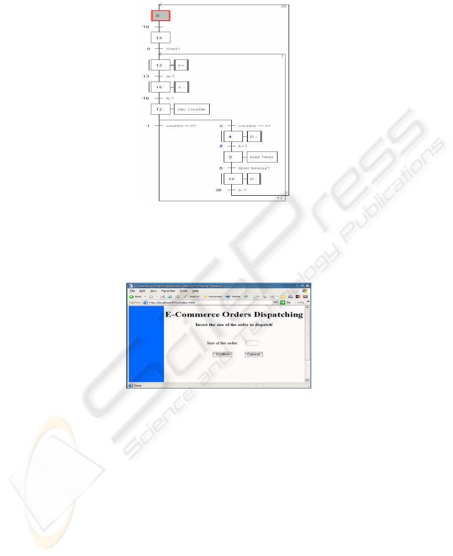
Fig. 6. Second problem implementation.
After this the main cycle of the order dispatch is completed. The next step was the
conception of the HTML interface (Fig. 7).
Fig. 7. Second problem HTML interface.
In this interface the user remotely inserts, in a Web browser, the size of the order to
dispatch and confirms it clicking in the “Confirm” button. Like in the first exercise,
previously described, HTML forms, with PDP keys embedded, were used to access
the PLC memory, with the help of Javascript functions. The “Confirm” button calls a
Javascript function that sets the PLC start flag and loads the counter. Next the finished
built program can be downloaded to the PLC, and remotely tested and debugged with
the SAIA Online Debugger.
The user can also see what’s happening in the laboratory with the previously referred
live video conference application (Fig. 8).
33
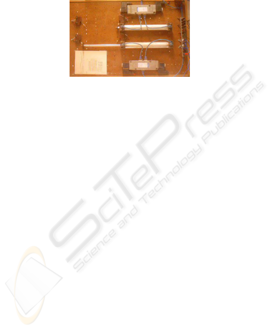
Fig. 8. Second problem remote live view of the Lab.
5 Conclusions
We presented a remote access automation lab allowing students to test both syntax
and semantic errors on their home work. The use of this tool increases the
productivity of laboratory sessions. Previous simulation of the logical functions of the
circuits has already provided good results as it was remarked by the student’s reports.
In this paper we present another step to let students, not only simulate, but have “real”
remote access to the equipment and test the correctness of their work.
Further work will implement a portal for controlling the access to the site. By now
only a password control is implemented in the PLC but a portal to control the access
to the experiment has to be implemented to control which user has exclusive access to
the equipment and to limit its use for a given time. Moreover we seek that the PLC
manufacturer might stand up a similar site allowing people to test a higher variety of
their equipments, allowing students to remotely work with equipments that may even
not exist in the laboratory.
This work was developed in a research laboratory supported by POCTI, FCT,
Ministério da Ciência e do Ensino Superior and by FEDER program. The
collaboration of the SAIA-BURGESS Local Representative “Infocontrol” was also
highly appreciated.
References
1. A. Leleve, H. Benmohamed, P. Prevot, C. Meyer, “Remote Laboratory Towards an
integrated training system”, ITHET03 Marrakech, MOROCCO, July 7-9, 2003
2. G. Guimaraes, T. Maffeis, L. Pereira, G. Russo, M. Bergerman, E. Cardozo, and F.
Magalhaes, "REAL: A Virtual Laboratory for Mobile Robot Experiments," 1st IFAC
Conference on Telematics Applications in Automation and Robotics, TA 2001, pp.209-214,
Weingarten, Germany, 2001.
34

3. D. Gillet, H. A. Latchman, Ch. Salzmann, and O. D. Crisalle, “Hands-on Laboratory
Experiments in Flexible and Distance Learning” in Journal of Engineering Education as an
Educational Brief (00-033), 2000
4. S. H. Chen, R. Chen, V. Ramakrishnan, S. Y. Hu, Y. Zhuang, C. C. Ko and B. M. Chen,
"Development of remote laboratory experimentation through Internet," in IEEE Hong Kong
Symposium on Robotics and Control, pp. 756-760, July 1999
5. C. Bonivento, L. Gentili, L. Marconi and L. Rappini, "A Web-Based Laboratory For Control
Engineering Education," in 2nd International workshop on tele-education using Virtual
Laboratories, August 8-9, Sherbrooke, Canada, 2002
6. C. Röhrig and A. Jochheim R, "The Virtual Lab for controlling real experiments via
Internet" in IEEE International Symposium on Computer-Aided Control System Design,
Hawaii, USA, 1999.
7. R. Delgado, G. Santos, C. Cardeira, R. Loureiro, O. Leichsenring, “Web-Based Supervision
of Remote Units”, accepted to Controlo’2004: the 6th Portuguese Conference on Automatic
Control, Faro, June 7-9, 2004
8. D. Bailey, E. Wright, SCADA for Industry, Newnes, 2003.
9. S. Boyer, SCADA: Supervisory Control and Data Acquisition, ISA - The Instrumentation,
Systems, and Automation Society, 1999
10. R. Neto, João Alves, Jorge Alves, A. Carvalho, I. Fonseca, N. Miguel, E. Emílio, H.
Fachada, "Remote Control of Industrial Processes", in Controlo’2000, Guimarães, October
4-6, 2000
11. Saia - Burguess, "Manual Web-Server Classic", document n. 26/790, Edition E2,
18.05.2003.
35
