
SERVICE INTEGRATION BETWEEN WIRELESS SYSTEMS:
A core-level approach to internetworking
Paulo Pinto, Luis Bernardo
Faculdade de Ciências e Tecnologia, Universidade Nova de Lisboa, P-2829-516 Caparica, Portugal
Pedro Sobral
Faculdade de Ciência e Tecnologia, Universidade Fernando Pessoa ,Porto, Portugal
Keywords: Interworking of wireless systems, wireless computing, handovers, mobility management
Abstract: The greater bandwidth provided by wireless LANs can be a precious asset to the wireless ubiquitous
computing if the integration with 3GPP systems is done at a certain level. This paper presents a proposal to
integrate wireless systems at core network level. Service integration becomes very powerful and easy. The
system is not so dependent on the critical latency of vertical handovers and the users feel a unique system
providing services. Little changes are required to the current 3GPP core network. Our architecture uses the
GPRS as the primary network and integrates WLANs as secondary networks, used on an availability basis.
Sessions on secondary networks survive disconnection periods contributing to a seamless service provision
to the user. The paper describes the overall architecture, the changes that are needed at the current 3GPP
core, and the operation of the secondary networks on the aspects of data routing and security associations.
Highlights about the application model are presented at the end.
1 INTRODUCTION
Cellular systems like Global System for Mobile
Communication/General Packet Radio Service
(GSM/GPRS), and its successor UMTS (Universal
Mobile Telecommunication System) already provide
IP-services in a ubiquitous mode. However, there are
obvious limitations on bandwidth due to their
coverage requirements. Wireless LANs (WLANs)
have been seen as a useful add-on to provide islands
of greater resources. Ways to integrate these systems
are being developed and a challenge discussed in
this paper is how the integration can be done to
allow new services to appear (e.g. exploring
mobility) and still support the existing ones.
Current proposals either envisage a complete
integration of WLANs in the cellular system’s
architecture (tightly coupled) or provide integration
in such a way that the systems interact poorly
(loosely coupled). The former solution does not
enlarge the type of services that can be designed
from the current cellular architecture framework and
the latter makes it difficult to provide a real sense of
service integration amongst the various access
networks.
This paper presents a solution based on an
integration performed at core network level amongst
the major components (such as the SGSN – Serving
GPRS Supporting Node). The system can be used in
different business scenarios and not only in a 3GPP
operator owned WLAN infrastructure. The paper
starts with a scenario of a service to justify why a
new approach to integration is viable. Our approach
maintains a user session regardless of the precise
Radio Access Network (RAN) used, claims that
vertical handovers (between RANs) are not needed,
and RAN switch can better be performed at core
network level (in the UMTS sense).
Each UE (user equipment) can maintain at least one
IP session over a specific RAN and can always use
the session, even when it is outside the coverage
area of that RAN (by using other active RANs).
Services can access core-level information to: (a)
improve the way they use the communication links
to the UE; and (b) handle and adapt to UE mobility
and connected periods (when the UE is inside the
coverage of a WLAN). In order to implement our
system only minor (software) modifications to the
current 3G core network need to be done.
127
Pinto P., Bernardo L. and Sobral P. (2004).
SERVICE INTEGRATION BETWEEN WIRELESS SYSTEMS: A core-level approach to internetworking.
In Proceedings of the First International Conference on E-Business and Telecommunication Networks, pages 127-134
DOI: 10.5220/0001384801270134
Copyright
c
SciTePress

2 ENVISAGED SCENARIO
Initial assumptions – First, the reality today is that
the cellular network is ubiquitous, covering 100% of
the populated areas. It is very unlikely that any other
radio network system will have such coverage. The
consequence is that any other network will have
dark areas, and supporting users in these networks
alone is not feasible. Second, our UEs are equipped
with two (or more) wireless interfaces working
simultaneously. Third, WLANs can be owned by
private organizations with agreements to the 3GPP
system operators or owned by the operators
themselves. Fourth, the security control provided by
the USIM smart cards and global roaming
agreements between 3GPP system operators form
the largest operational security system in the world
to date. AAA (Authentication, Authorization and
Accounting) procedures between 3GPP systems and
WLANs are on the verge of being approved (3GPP,
2003) and we assume them in our system.
Download service – Our service example extends
the infostation model presented in (Frenkiel, 2000)
with cellular network integration (the real subject of
the example – download of data – could be part of a
more sophisticated application).
A user is at home and uses the GPRS interface to
start a service to download some bulk data. In his
way to work, the system will try to use the WLAN
RAN (near semaphores, etc.) to deliver the data.
Eventually, all the data will be transferred.
In the rest of the paper, we consider GPRS as a
packet service in both 2.5G and 3G systems
standardized by 3GPP.
3 SYSTEM OVERVIEW
The capacity of radio cells will increase in the
future. Cells will be smaller than the current ones.
As stated in (Frodigh, 2001) we also agree that
extremely high rates will not be necessary
everywhere, but just in small hotspots. The question
is how to integrate these hotspots?
3.1 Hotspot Integration
One possibility is that they are part of the cellular
network as an ordinary cell. The network would
predict the user movement (using the cell
information) and could schedule the sending of large
bulks of data when a hotspot becomes available.
However, implementing such a facility at network
level can be rather complex (as there is not enough
relevant information). Moreover, unless applications
have knowledge of the differences in cells and adjust
to specific cell data rate conditions a user might
experience lack of bandwidth just because he
stepped out of the coverage.
Another possibility is that high bandwidth cells are
seen as special cells, not integrated in the cellular
system and having a special (direct) connection to a
packet data network. The user knows he is using a
different interface and stepping out of coverage is
easy to detect.
There are proposals for WLAN integration covering
both possibilities. The tightly coupling option
(Salkintzis, 2002) state that cells should be
integrated at a low level offering an interface
compatible with the 3GPP protocols. Besides the
drawbacks listed above there are still the following
disadvantages: (a) the WLAN must be owned by the
3GPP operator (to avoid strong exposure of core
network interfaces); (b) cell displacement and
configuration demands carefully engineered network
planning tools and WLAN integration becomes
difficult. Moreover, a great deal of control
procedures are based on configuration parameters
(CellID, UTRAN Registration Area (URA), Routing
Area (RA), etc.) and WLAN cells have to comply
with them; and (c) paging procedures and handovers
(including vertical handovers) have to be defined
and some technologies (e.g. IEEE 802.11) are not so
optimized to make them fast enough.
The loosely coupled option (Salkintzis, 2002 and
Buddhikot, 2003) assumes there is a WLAN
gateway on the WLAN network (with functionalities
of Foreign Agent, firewall, AAA relaying, and
billing) and the connection to the 3GPP core is via
GGSN (Gateway GPRS Support Node) (with a
Home Agent functionality). It only makes sense to
use this option with dual-mode UEs because a
vertical handover to WLANs would disconnect the
UE from all the functionality of the cellular
networks (paging, etc.). One advantage is that high-
speed traffic is never injected into the 3GPP core
network. A major disadvantage is the degree of
integration. WLAN networks are handled
independently and will be used on an availability
basis by the users, whom have to stay within the
same coverage. Any service provided by the 3GPP
(SMS (Short message Service), etc.) has to consider
the cellular system’s internet interface. Any
exploitation of the UE’s mobility (both in the
cellular system and inside the WLAN island) is
hidden by the mechanism of Mobile IP, for instance.
From the applications point of view, the UE is
stationary placed inside a big cloud called GPRS (or
WLAN). I.e. it has a stable IP address and any
mobility inside the 3GPP network is not seen from
the exterior.
ICETE 2004 - WIRELESS COMMUNICATION SYSTEMS AND NETWORKS
128
3GPP (3GPP, 2002) defined six scenarios of
increasing levels of integration between 3GPP
systems and WLANs. Scenario 3 addresses access to
3GPP PS services and includes access control and
charging. (3GPP, 2003) specifies how it should be
done. A loosely coupled approach was adopted but
the data routing aspects are still not fully agreed (the
specification covers mostly the access control and
charging).
Our proposal for hotspot integration is somewhere in
between the tightly and loosely options – it is at core
network level. It allows the use of WLANs as a
complement to the GPRS network. It is not fully
incompatible with the 3GPP effort, as it will be
described below.
3.2 Primary and Secondary Networks
In our system the GPRS network is the glue for all
the other RANs. It is the primary network having all
the control services (paging, etc.). All secondary
networks become simpler and can have control
services of their own not seen at core level (i.e. they
are simply internal optimizations). Almost all of the
works in internetworking assume that all these
features (including paging) exist in all networks and
are seen at core level. IDMP (Misra, 2001) is one of
the exceptions stating that they should be
customized. The most similar approach to ours was
taken by MIRAI (Wu, 2002). Their primary network
is a collection of BANs (Basic Access Network).
Each BAN contains the usual control services, and is
controlled by a CCN (Common Core Network)
manager. A user selects a RAN based on a list
provided by the BAN considering user location and
preferences. Although, the authors consider a long
list of issues to help the UE choose the RAN, some
too low level or “external” reasons (e.g. battery life)
can lead to unexpected choices from the
applications’ point of view. CCN handles micro-
mobility (possibly inter-RAN) and participates in
macro-mobility. The control features of the BAN are
very similar to the ones in UMTS. It could have
been implemented by the 3G system (as also stated
in (Wu, 2002)) but MIRAI authors decided to
implement a new radio interface.
In our system a WLAN RAN is a set of islands.
Each island is formed by a set of cells and is
controlled by an Island Manager (IM). Islands do not
cover the entire space (i.e. there will be dark areas).
All islands of a certain technology are seen by the
primary network as a Hotspot Network (HN) – a
secondary network.
A user is connected to the GPRS network and can
have other sessions simultaneously. Each HN
supports the notion of a session (i.e. IEEE 802.11
has one, HiperLan has another, etc.). Differently
from the other proposals is the fact that a session
survives the disconnection periods when the user is
moving in a dark area of a certain WLAN. For
instance, the user began a 802.11 session at the
airport, took a taxi to a hotel, and when he is in the
hotel, the same session is still on using the WLAN
infrastructure of the hotel (it is assumed that both
have agreements with 3GPP operators). On the way
from the airport to the hotel, if the user needs to be
contacted in the context of that session the primary
network is used.
Other works consider all RANs at the same level.
(Tönjes, 2002) defines a flow router at the core that
uses all RANs. This will lead to the existence of
control functions in all of them. If only one is chosen
to have these features the system will fall back to
ours. Moreover, with a monolithic core it would be
more difficult to add a new RAN.
4 ARCHITECTURE
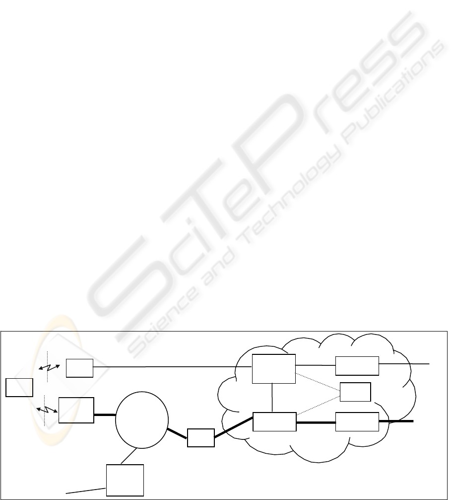
Figure 1 shows the architecture for the data traffic
Figure 1: Data traffic in the hybrid networ
k
UE
WLAN
AP
IM
L2
distribution
network
WLAN radio
interface
3G
SGSN
core
network
BS
UTRAN radio
interface
HNAC
GGSN
GHSN
IP
a
IP
1
IMSI
IP
2
HSS
Local
Route
r
IP
3
A
SERVICE INTEGRATION BETWEEN WIRELESS SYSTEMS: A core-level approach to internetworking
129

(no access control, billing, etc.). The new
components are the HNAC (Hotspot Network Area
Controller) which controls one (or more) island, and
the GHSN (Gateway Hotspot network Support
Node) which is responsible for context management
and Internet access. The thicker lines belong to the
core but they are not present in the current 3G core.
All the high speed traffic goes through them not
overloading the current 3G infrastructure.
The 3GPP specification for scenario 3 (3GPP, 2003)
has a component that merges the HNAC and the
GHSN, called PDG (Packet Data Gateway). The
PDG is not connected to the SGSN (line A) as we
propose and all data integration between the systems
is done at IP level.
An UE has its identification at core level in the form
of an IMSI (International Mobile Subscriber
Identity) and the attachment procedure for GPRS is
the standard one (with temporary identifiers). In the
GPRS world an IP session can be established via the
GGSN (PDP context), having a routable address,
called IP
1
.
If the UE senses a WLAN to which it can perform a
connection establishment, it does so. From that time
on it can use the ‘local router’ to access the Internet
directly. An IP
3
address is used for that path
(whether this address is a care-of-address and
whether the local routing is performed at level 3 or
level 2 is irrelevant to this paper). If the WLAN has
roaming agreements with a 3GPP operator the UE
can perform an attachment procedure with the 3GPP
operator (3GPP, 2003). The attachment defines a
local identifier at core level for the UE in that
WLAN (possibly with temporary addresses, too). In
figure 1 an IP address was used as an example for
the local identifier (IPa). From this time on an UE
identified by the IMSI can be contacted via UTRAN
using the IMSI, or via WLAN using the IPa. It is
important to note that no assumption is made about
an all-IP technology in our system. It is sufficient
that it is IP-enabled. I.e. the UE communicates at IP
level with the core, but the core forwards packets to
the IM to be delivered to an UE with a specific local
identifier. The core does not assume any delivery
protocol in the island. The IM can use a layer 2
routing if it suits better. The important thing is that
IPa is stable. If the UE wants to use the Internet via
the WLAN it creates a PDP context (in similar
modes as to the GPRS case) and a routable address
IP
2
is defined at GHSN. Every time there is an attach
update (in a different WLAN, for instance) a new
IPa is chosen but IP
2
remains the same.
IP
1
is the main, fixed, UE address. IP
2
and IP
3
should be used on a temporary basis (e.g. client
applications). Therefore, reuse of addresses can be
made making the system scalable.
4.1 Overview of the Interactions
The HSS (Home Subscriber Server) has the
operational information about the UEs. Besides the
GPRS-related parameters that the HSS already has,
there is the information if an UE is HN attached, has
a session established and if it is currently inside a
WLAN coverage area (and the identification of the
HNAC responsible for it). SGSN and HNAC will go
to HSS to get updated information. The HSS also
provides authentication vectors, subscriber profiles,
and charging information.
The communication between the core (SGSN and
HNAC) and the UE can use any RAN. We will
describe two approaches: the first one, the smooth
transition, consists in keeping the GPRS almost as it
is with little add-ons. Any PS traffic will use
UTRAN but the HNAC can communicate directly
with the UE via WLAN, or can relay the traffic
through the SGSN to be delivered to the UE via
UTRAN (using the interface link A in figure 1. A
more concrete description is given below); the
second approach is more abrupt – both SGSN and
HNAC can convey their traffic through the other
component if they see some advantage. Currently, a
tunnel called GTP-U (GPRS Tunneling Protocol –
for User Plan) is established between the GGSN and
the serving RNC (Radio Network Controller). In our
second approach the tunnel goes as far as the SGSN
and a new tunnel is formed from there on. It is a
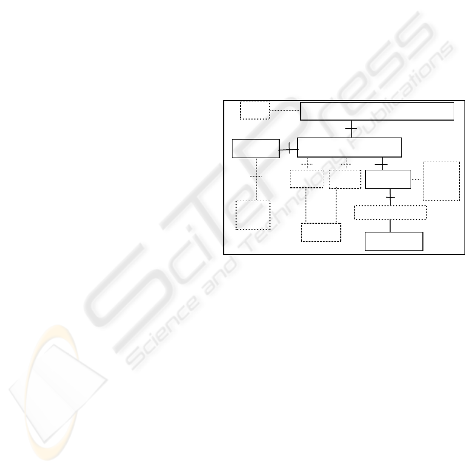
return to the original GPRS specification. Figure 2
shows the protocol stack at an UE. There is a
Connection Manager (CM) that manages the status
of both connections and offers a unique interface to
both RANs. The Delivery Service is a confirmed
service and switches to the UTRAN if it senses a
failure in the WLAN. If more than one RAN is
active the default one for each message is used. The
CM can signal the applications (or be queried by
them) about the current status of a specific
connection. With this information, applications can
L1/L2
L1/L2
Connection
Manager
(CM)
UTRAN
WLAN
Applicat. A Applicat. B
Figure 2: Protocol stack at a UE
IP
Session Control
Delivery Service
ICETE 2004 - WIRELESS COMMUNICATION SYSTEMS AND NETWORKS
130
avoid using the link if the proper interface is not
active (transferring only urgent information, for
instance). The CM is able to contact each of the core
network components (SGSN or HNAC) either
directly or via the other RAN (for link maintenance
messages, etc.). The Session Control is responsible
for session survival when the UE is in dark areas.
For the smooth approach the following interactions
are needed: (a) permission by the SGSN to create a
session between the UE and the HNAC (using a
PDP context just as the GGSN uses them, with the
Session Management Protocol) (Kaaranen, 2001). A
GTP-U tunnel is created between the HNAC and the
UE (more precisely with the serving RNC); (b) an
event service from the SGSN to notify relevant
events – “UE availability”, “cell update”, “routing
area update”, “positive cell identification” and
“undefined cell identification”. It is important for
session management by the HNAC; and (c) mobility
management information by the SGSN (cell
identification if in GPRS state ready, or routing area
identification, otherwise) - it can be useful for the
HNAC. Suppose HNAC has a relation between cells
and WLAN islands topologies. It can force the
WLAN interface to switch off if no islands are
known in a certain routing area, for instance. It is
also important because HNAC change of
responsibility can happen when the UE performs a
routing area update.
For the abrupt approach the current GTP-U tunnels
have to be divided in two parts: one from the GGSN
to the SGSN; and another from the SGSN to the
RNC. The same will happen from GHSN to HNAC,
and from HNAC to IM. This separation allows the
second tunnels to be established either via the
default RAN, or via the other RAN.
4.2 Scope of Integration
In our system there is no need for vertical handovers
because the GPRS session is always on and the other
RANs are used as a complement. Communication to
the UE can use indistinguishably any available
RAN. A total switch of the communication from one
RAN to another is performed by the core
components, so no information is ever lost. In
systems with traditional vertical handoff, the
dominant factor is the time the UE takes to discover
that it has moved in/out of coverage (i.e. the cell has
to become active or inactive) (Steem, 1998). Using
RANs in a complementary form as we do, this time
is not so critical, and the GPRS can provide a
minimal bandwidth.
As the integration is performed at core level current
services can work with secondary RANs in a very
easy way. Figure 3 (taken from (3GPP, 2003))
shows how 3GPP plans to support SMS over
WLAN. A service specific gateway, IP-SM-GW,
must exist and offer an interface similar to an MSC
or an SGSN (interfaces E or Gd) to the GMSC/SMS-
IWMSC. The address of this gateway is returned by
the HSS in the “send routing information for short
message”. This gateway has a private database to
associate MSISDN to IP addresses. UEs in WLAN
have to specifically register and specifically
authenticate for SMS services and have secure
associations to the gateway. The gateway
communicates with the UE via Internet.
In our system (abrupt approach), the SMS service
could be provided without any modification. The
SGSN just gets the message and can use the HNAC
to convey the message to the UE, using the secure
associations that are already in place.
4.3 Application support at core level
HNACs have already the task of maintaining
sessions between appearances of the UE in WLAN
islands. A step further is their ability to work with
the applications in order to take advantage of the
mobility (and connect times) of the UEs to perform
the application task in a specific manner. This is not
the traditional approach in the Telecom world and
resembles more the activity of a middleware level
managing mobility.
In the Telecom world networks are seen as closed
systems that offer services. Services are carefully
specified procedures that use lower level procedures
called bearer services. The control procedures of the
network are seldom accessible from the exterior and
well protected from external components. It is
interesting to see that the same approach is being
planned for the introduction of Voice over IP (VoIP)
services (Lin, 2002) on top of GPRS. The RAN and
SM-SC
GMSC / SMS-IWMSC
IP-SM-GW
HSS/
(
HLR
)
UE
WLAN UE
MSC
E
E’ or Gd’
SGSN
G
d
WLAN
AAA
Wx/(D’/Gr’)
PDG
Wi
C
SME
IP
address
database
Figure 3: Support of SMS over WLAN
SERVICE INTEGRATION BETWEEN WIRELESS SYSTEMS: A core-level approach to internetworking
131

the GPRS network together are called the bearer
network. Through the Gm interface (which includes
radio, Iu, Gn, and Gi), the bearer network provides
bearers for signaling (control plane) and data (user
plane) between the UE and the IP Multimedia
Subsystem (IMS) (placed outside the core network).
The bearer network nodes (RAN, SGSN, and
GGSN) are not aware of the multimedia signaling
between the UE and the IMS.
The typical way to add new functionalities and
behaviors to networks is using frameworks such as
Intelligent Networks, or in case of UMTS, the
CAMEL (Customized Applications for Mobile
network Enhanced Logic), (Kaaranen, 2001).
However, the extensions are traditionally related
with the basic services and with inter mobile-
network interactions. For instance, personalization
of services, different control over switched circuits,
virtual home environments when roaming, etc.
In our system, HNACs can have a standard (and
protected) programming interface to be used by
third-party organizations to build services and
applications that take advantage of the information
gathered at the core (and not accessible today). The
end of this paper has an example of one.
5 HN OPERATION
The interaction between an island and its controlling
HNAC is performed by the Island Manager (IM).
The IM provides a stable identifier for the UE and
forwards packets between the UE and the HNAC. In
terms of security the 3GPP network can offer an
authentication service to the WLAN owner (WLAN
connection establishment is not covered by the
3GPP specification, obviously). It is important that
both networks rely very little on each other (not
disclosing authentication vectors, for instance).
Figure 4 shows the proposed setup. It consists of
two, almost similar, phases. The first provides
WLAN authentication assisted by the 3GPP
network, and the second provides 3GPP
authentication via WLAN. The UE senses a WLAN
and creates a provisional secure association with the
local router (LR) (1) (it is assumed that the AAA
functionality is inside the LR). Using this
association it sends a message to the LR to state its
willingness to authenticate. The LR triggers an
authentication process within the HNAC. The
HNAC gets authorization vectors from the HSS and
issues a challenge. The local router relays the
challenge and the corresponding response between
the HNAC and the UE (using, for instance EAP
Response/Identity) (2). The result of the
authentication is given to the LR by the HNAC
(EAP-Success/EAP-Failure) (3). At this moment the
LR knows the UE has the identity it claims it has.
The LR checks if the UE can use the WLAN, by
consulting a local database of users. If so, it creates a
definitive secure association (in the scope of
WLAN), provides the keying material to the UE for
local WLAN use, and informs the address of the IM.
The 3GPP could also approve a user not belonging
to the local WLAN community, in which case the
LR will tell the user that a local session cannot be
established but the IM address is given for a WLAN-
3GPP session.
If the UE has passed the first phase, it can now
start an authentication process with the 3GPP to
create a context there (4). The secure association is
created with the 3GPP without intervention, or
knowledge, of the WLAN. The attachment to the
3GPP network is covered in (3GPP, 2003) and uses
the EAP authentication procedure, providing enough
keying material for a secure tunnel to the PDG (or
HNAC in our case) through the IM. Once attached,
the HSS has the indication that the UE exists and a
session can be established (both by the UE and by
the 3GPP). A WLAN session can also be established
using the UTRAN interface (particularly useful in
dark areas). Each time a new island is entered a fast
update procedure must be done.
The concrete mobility management protocol used
inside the island and any mechanism to save power
or bandwidth are irrelevant and should not be seen
from the 3GPP. I.e., a micro-mobility move must not
change the local (IPa) address to maintain the secure
associations and the information in the core. Any
possible paging mechanism prior to the delivery of a
message is also hidden from the 3GPP. From the
core level point of view a packet is simply delivered.
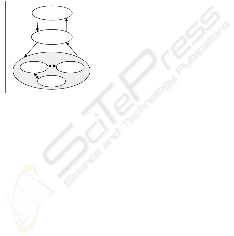
Figure 5 shows the state diagram of the
interaction UE-3GPP. It is assumed that the UE is
always attached to the GPRS. Its idle state is the
Disconnected state – there is no operational WLAN
information about the UE in the core.
When the UE attaches and creates a PDP
context, the address IP
2
is defined, and the HSS has
information about its existence. An HNAC will be
Figure 4: Security flows for UEs
UE
AP
LR
IM
DB
1
2
3
4
L2
networ
k
3GPP
ICETE 2004 - WIRELESS COMMUNICATION SYSTEMS AND NETWORKS
132
responsible for it and the state changes to
Registered. In this state it is assumed that the UE is
always reachable via IP
2
.
Any communication to/from the UE is done in
the context of a session. A session represents extra
attention by the HNAC to the position of the UE
(using also the mechanisms provided by the SGSN
as stated above). The Session state is entered when
either the UE or the HNAC issue a Start of Session
message. The sub-state Connected means that the
UE is inside an island. The sub-state Searching is
entered when the UE is out of coverage. In the
Searching sub-state, the HNAC forces the UE to be
in active GPRS state to know its cell ID. It can
happen that the UE is in a cell that has no islands
nearby. In this case the HNAC can order the UE (via
UTRAN) to go to sub-state Waiting to save battery
power. When the UE moves to a cell where an island
exist it is told to change again to Searching (note
that these sub-states are simply optimizations and
can exist, or not).
Depending on the application it can be easy to know
when a session finishes, or not. If it is, an End of
Session message is sent. If it is not, a watchdog
mechanism based on inactivity triggers the sending
of the message, for instance.
6 APPLICATION MODEL
Applications may interact with external networks
using one of the three connections: UTRAN (IP
1
),
WLAN direct (IP
3
) or WLAN-HN (IP
2
). The
application models for the first two follow the
traditional Internet models – correspondent nodes
communicate with fixed remote IP addresses and
send data as soon as it is available. For the WLAN-
HN we can have a different approach that optimizes
the use of scattered hotspots over a ubiquitous 3GPP
network. With proper support at the core network,
these applications will be able to maintain sessions
independently of the hotspot availability, and
communicate the bulk part of the data only when the
UE is in the Connected sub-state.
Application functionality is divided between the
UE and the serving HNAC (figure 6). In the UE we
have a front-end component implementing the user
interface and interacting with the session control
entity and the associated lower services (which
behave as a middleware platform for the
applications). In the serving HNAC we have the
back-end component that cooperates with its peer on
the UE and maintains a stable interface with external
entities. By stable it is meant that any optimization
use of the air interface is hidden from the external
applications. These components work in the context
of the IP
2
session (Fig. 1), but can communicate with
each other using the WLAN RAN or the UTRAN.
They can work in an “Always Connected” mode,
using the SGSN each time the UE is in an HN dark
area, or, more interestingly, in “Hotspot Connected”
mode, communicating only urgent information via
SGSN while waiting for the UE to become
Connected again.
The middleware performs session and mobility
management providing applications with context
information. The middleware layer gathers UE
mobility information from the SGSN and network
status from probing its network interfaces. These
events are used by the middleware services to update
the execution environment parameters. Using this
information, applications are able to adapt their
behavior to different network conditions and
mobility scenarios.
For instance, if a user wants to download a news
summary stored in a web site, both components start
a new session, and the back-end component will start
to fetch the videos. If the UE gets out of coverage
the back-end component can store a portion of the
data waiting for the UE to pop up. Later, when the
UE enters into a hotspot, the information will be
forwarded to the front-end component. In the
meantime both modules can exchange control
information via the SGSN/UTRAN. This pre-
fetching feature optimizes UE connection time with
HN, avoiding fetching delays from exterior
networks. The back-end context has to be highly
mobile because it might have to change to another
HNAC pursuing the UE (dashed arrow in the
figure). Information can be stored either in the
HNAC or in a server close to the core network with
a guaranteed delay for access (avoiding copying
when the serving HNAC changes).
Re
g
istere
d
Disconnected
Session
HN Attach
Pr
ocedu
r
e
HN Detach
Pr
ocedu
r
e
Connecte
d
Searching
Waiting
Start of
Session
End of
Session
Figure 5: UE-3GPP State Diagram
UE-3GPP State Diagram
SERVICE INTEGRATION BETWEEN WIRELESS SYSTEMS: A core-level approach to internetworking
133

7 CONCLUSIONS
The internetworking of wireless infrastructures
performed at core level with a pivot network seems a
simple and executable model. First, as most of the
control features already exist in the PLMN, they can
be absent in other networks. Second, because certain
details on secondary networks (such as micro-
mobility) are not managed at core level. Third,
because it defines an environment where new
features and services can be added to the core.
The addition of new modules at core level with
standard (and protected) programming interfaces can
open up new possibilities to explore terminal
mobility (a topic that is absent today).
Our solution does not impose relevant
requirements to the overall system: the architecture
does not need to be all-IP; there is no critical
dependence on vertical handovers; and, does not
create extra load to the current 3GPP core network.
Topics that are relevant for further work include the
algorithms to be used on top of the HNACs to
explore the mobility of UEs and their connection
periods, and the viability of service continuity using
this type of handovers.
REFERENCES
3GPP, 2003. Group Services and System Aspects; 3GPP
system to WLAN internetworking; System
Description (Release 6), TS 23.234.v.2.3.0, Nov.
Frenkiel, R., et al, 2000. The Infostations Challenge:
Balancing Cost and Ubiquity in Delivering Wireless
Data, IEEE Personal Communications, v.7, pp66-71,
n.2, April.
Frodigh, M., et al, 2001. Future-Generation Wireless
Networks, IEEE Personal Communications, v8, pp 10-
17, October.
Salkintzis, A., et al., 2002. WLAN-GPRS Integration for
Next-Generation Mobile Data Networks, IEEE
Wireless Communication, v.9, pp 112-124, October.
Buddhikot, M., et al., 2003. Design and Implementation of
a WLAN/CDMA2000 Interworking Architecture,
IEEE Comm. Mag., pp 90-100, November.
3GPP, 2002. Group Services and System Aspects;
Feasibility study on 3GPP system to WLAN
internetworking; (Release 6), TS 22.934.v.6.1.0, Dec.
Wu, G., 2002. MIRAI Architecture for Heterogeneous
Network, IEEE Comm. Mag., pp 126-134, February.
Tönjes, R., 2002. Flow-control for multi-access systems,
PIMRC’02, pp 535-539, September.
Steem, M., Katz, R., 1998. Vertical Handoffs in wireless
overlay networks, Mobile Networks and Applications,
v.3, pp 335-350.
Lin, Y., et al., 2002. An All-IP Approach for UMTS
Third-Generation Mobile Networks, IEEE Network,
v.16, n.5, pp 8-19 September/October
Application
Front-End
Component
Session
Control, etc.
Application
Back-End
Component
Session
Co
ntr
o
l
,
e
t
c
.
Application
Back-End
Component
Session
Control
,
etc.
SGSN
UE
HNAC HNAC
Figure 6: Functional Blocks for HN session applications
ICETE 2004 - WIRELESS COMMUNICATION SYSTEMS AND NETWORKS
134
