
MODELING AND MANAGING
FEDERATED WEB-BASED SYSTEMS
Johannes Meinecke
1
, Martin Gaedke
2
, Frederic Majer
1
and Alexander Brändle
3
1
Institute of Telematics, University of Karlsruhe, Engesserstr. 4, 76128 Karlsruhe, Germany
2
Distributed and Self-organizing Computer Systems Group, Chemnitz University of Technology Straße der Nationen 62
09107 Chemnitz, Germany
3
Microsoft Research Cambridge, 7 JJ Thomson Avenue, CB3 0FB Cambridge, United Kingdom
Keywords: Security, Web Services, Architecture, Modeling, Federation, Service Architectures.
Abstract: Among the various aspects of Web applications that are subject to modeling, like navigation, interaction or
business processes, the architectural aspect is receiving growing attention. This is related to the fact that the
Web is increasingly used as a platform for distributed services which transcend organizational boundaries to
form so-called federated applications. In this context, we use the term “architecture” to denote the
composition of the overall solution into individual Web applications and Web services that belong to
different parties and invoke each other. The design and evolution of such systems calls for models that give
an overview of the federation structure and reflect the technical details of the various accesses. We
introduce the WebComposition Architecture Model (WAM) as an overall modeling approach tailored to
aspects of highly distributed systems with federation as an integral factor.
1 INTRODUCTION
The needs of modern businesses that operate
worldwide, cooperate with various partners, and
deliver their services in real-time pose complex tasks
to be solved by technological disciplines. Over the
years, this trend of connected businesses has
affected the Web and lead to a change towards a
platform for distributed applications. Beyond merely
supplying documents to users, it has recently been
used as a communication infrastructure that links
together applications, e.g. by exposing functionality
through Web services. Now, a tendency can be
observed towards a new class of applications that is
made possible by these technological advancements:
the federated portal respectively 4
th
generation portal
(Gootzit and Phifer 2003). The relationships within
such federations of portals belonging to multiple
organizations do not only consist of simple HTML
links, but comprise the connection of the portal
backbones, i.e. they also share for example data,
functionality or user accounts.
However, the added business value brought by
the new sophisticated approaches does not come for
free. Besides the challenges involved with federating
applications on a semantic level, e.g. addressed in
(Park and Ram 2004), the typical characteristics of
these enabled solutions cause a high degree of
technical complexity. In the context of federation,
the question of access control and security is
especially important and requires the application of
advanced concepts (Cameron 2005). This is related
to the fact that in such scenarios, external users from
cooperating organizations have to be granted access
to local resources while preserving the autonomy of
the individual federation partners. All system
characteristics are subject to change during the
evolution of the federation and its components.
During the system lifetime, new services may be
added, removed or substituted by others and new
partners can join or leave the federation.
The mentioned factors accumulate to a complexity
that requires systematic methods for modeling,
building and operating concrete systems. To this
end, we propose the WebComposition Architecture
Model (WAM), which we describe in the remainder
of the paper. We identify three key requirements that
we believe to be vital for modeling the architecture
15
Meinecke J., Gaedke M., Majer F. and Brändle A. (2007).
MODELING AND MANAGING FEDERATED WEB-BASED SYSTEMS.
In Proceedings of the Third International Conference on Web Information Systems and Technologies - Internet Technology, pages 15-22
DOI: 10.5220/0001261200150022
Copyright
c
SciTePress

of the outlined type of application. We then provide
a broad overview of related modeling languages and
introduce our own WAM approach as well as an
XML-based notation that can be used to provide
WAM models in a machine-readable way. This
format is used by a service-based support system,
whose application within an integration project is
outlined.
2 MODELLING CHALLENGES
When the architecture of a system is modeled, there
is a wide range of different potential aspects to be
described and viewpoints to be taken. From a
software engineering point of view, (Bass, Clements
et al. 1998) defines the term architecture as “the
structure or structures of the system, which comprise
software components, the externally visible
properties of those components, and the
relationships among them”. In our federation- and
Web-specific case, the system can be conceived as
the federation that consists of Web services and
applications forming the components. To establish
some guidance for a modeling approach targeted at
such architectures, we have derived the following
key requirements from the system characteristics.
2.1 Challenges
Integration of security concerns into architecture
models: One of the described particularities of the
targeted type of application is the fact that accesses
transcend organizational boundaries. In this context,
the term security is related to the precautions to
secure authentication and authorization, which is
necessary to guarantee compliance with the partners’
access policies. In conventional solutions with only
one organization involved, this can be realized with
a zone concept. This is often achieved by combining
firewalls and virtual private networks (VPN) with
implicit trust between the system parts inside the
zone. Here, the focus often lies on modeling the
primary functional structure first and taking security
into account later on. The major difference in
federated applications is the existence of not just one
zone, but multiple zones; with the accesses
depending on trust relationships between the
controlling organizations. This underlying trust
network may also affect the structure of the system,
e.g. with respect to whether a service can be used by
an application or not. Consequently, we propose the
integration of security considerations into the same
model that is already being used to describe the
system architecture.
Hiding unwanted complexity: Models of federated
systems have to cope with a high degree of
complexity, partially caused by advanced federation-
enabled security protocols, as e.g. token-based
approaches. For example, when a user logs into a
portal and queries information from a service, this
may involve the exchange of a high number of
messages in order for the token to be requested,
issued and transported to the protected service
before the access is granted. While this could be
modeled e.g. with a UML sequence diagram, the
exact succession of calls may in many cases have no
relevance for the real modeling purpose. What is
rather required is an abstraction from such details
that actually supports the process of communicating
the model to others. Preferably, we are interested in
a notation that is simple enough to be drawn using
pen and paper to sketch the most important facts and
powerful enough to add further details on demand.
Bridging the gap between model and system: The
fact that federations are subject to frequent changes
can cause a gap between the model and the modeled
reality. If the model takes the form of a diagram on
paper or in a document with a vendor-specific
format, it is in danger of being constantly outdated
and therefore useless to work with. In order to close
this gap quickly enough, one approach is to rely on
machine-readable representations that can be
processed by tools. Hence, this would enable
automatic updates of the model (system to model),
as well as make the contained metadata available to
operations that change, maintain or otherwise
support the system (model to system).
2.2 Related Work
In the following, several existing approaches facing
the challenge of modeling the architecture of highly
distributed and interconnected Web-based systems
will be described briefly and examined regarding our
derived key requirements.
The first generation of architecture modeling
approaches was focusing on a separation of concerns
by specifying dedicated layers for different aspects
of the system. These approaches share a common
view on the importance of some concerns. Kirchner
(Kirchner 2005) specifies a Business Process Layer,
a Software Layer and a Hardware Layer. The project
ARCUS (Hermanns, Jänsch et al. 1999), which
aimed at architectural support for systems in the
banking sector, introduced an additional layer for the
WEBIST 2007 - International Conference on Web Information Systems and Technologies
16
specification of technical terms regarding the
problem domain. Still, both approaches are designed
to reflect the system architecture of an enterprise and
do not take identities and applications transcending
organizational boundaries into account. Support
through machine-readable system descriptions is
also beyond their scope.
More recently, new approaches like the Dynamic
Systems Initiative (DSI), the Data Center Markup
Language (DCML) and the Systems Modeling
Language (SysML) have been introduced that try to
close the gap between model and system. DSI is a
technological strategy devised by Microsoft that
aims at an integrative support for the design,
deployment and operation of distributed systems
(Microsoft 2003). The initiative is driven by the idea
of combining the two processes of building and
operating IT solutions to emphasize the application
life cycle as a whole. Although the approach deals
with modeling systems in general, its major focus is
on the Windows platform. DCML is an approach to
describe data center environments, dependencies
between data center components and the policies
governing management and construction of those
environments (OASIS 2004). As an application of
the XML, it provides a platform-independent
specification, and is not restricted to any product but
to the context of a data center. As an example of an
approach that tries to merge these ideas on an
abstract system level, SysML focuses on the
specification, analysis, design, verification and
validation of systems and systems-of-systems based
on UML (SysML Partners 2005). Trying to focus on
all kinds of systems in general, this approach has a
big potential, but does take neither security nor
federated identities into account.
Approaches that specifically target the
systematic modeling and operation of Web-based
systems are covered by the discipline Web
Engineering. Many of them provide design
methologies for dealing with the various aspects of
Web applications, including navigation, interaction
and business processes. For example, WebML,
OOHDM, UWE and HERA (Kappel, Pröll et al.
2006) stress the hypermedia aspect of Web
applications, focusing an application’s composition
from individual pages and navigatable nodes rather
than a Web-based system’s composition from
individual services and applications. WebSA (Meliá
and Cachero 2004) applies the model-driven
development paradigm by combining architectural
models with the design methods mentioned above.
Although WebSA does not suffer from the model to
system and system to model problem, due to the
model-driven approach, there is no integration of
security and federated identities as a requirement.
3 WAM MODELING APPROACH
In the following sub sections, we describe the
overall WAM modeling framework, give an
overview of the graphical notation of WAM and
briefly describe an approach to enrich system
descriptions with necessary technical details.
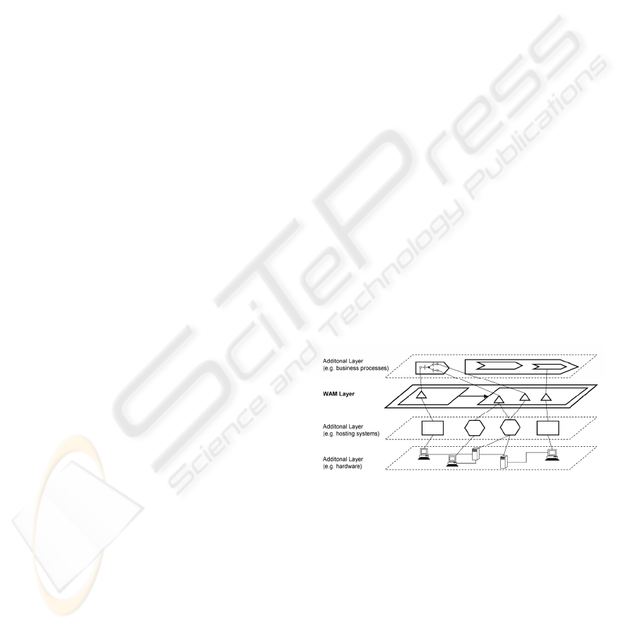
3.1 Modeling Complex Systems
With reference to the desired reduction of
complexity in system engineering, it is not advisable
to try covering all aspects of a federation’s
architecture in one model. Therefore, our approach
takes the separation of system concerns into account
and is based on a framework of multiple models that
each target different concerns or system layers (cf.
Figure 1). In this context, WAM is understood as the
foundation model that is intended to cover the most
vital aspects of federated systems. More layers can
be added as extensions, possibly by third-parties, to
describe concepts that are not part of WAM and that
might be specific to certain tools for processing the
contained information. The various models are not
totally independent, as the modeling entities residing
in different layers can often be related to each other
with inter-model relationships.
Figure 1: Model layers with inter-model relationships.
The framework restricts the potential model
structure by prescribing as a minimal condition the
taxonomy of model constructs: All Model elements,
(usually represented by dedicated symbols) are
either Entities, which can be mapped to objects or
concepts of the modeled world, or directed
Relationships, which link multiple entities, possibly
across different model layers. As a fixed built-in
relationship, entities can be assigned to parent
entities of which they are a part of. This introduces a
MODELING AND MANAGING FEDERATED WEB-BASED SYSTEMS
17
structural hierarchy among entities to account for the
architectural focus of the models.
3.2 WAM Graphical Notation
In order to account for the integration of security
concerns into architecture models, WAM adopts
general concepts from the state of the art of
federated identity and access management protocols.
Currently, there are several specifications being
worked on that follow an approach based on so-
called security tokens, including WS-Federation
(Bajaj, Della-Libera et al. 2003), SAML (Maler,
Mishra et al. 2003) and the Liberty Alliance project
(Liberty Alliance Group 2004). Common to all
specifications, such tokens take generally the form
of digitally signed XML documents that contain
security-relevant statements which can be exchanged
between different system entities. The statements are
usually either a proof of identity (e.g. of a user that
wants to log into the system) or a proof of privileges
(like e.g. the set of roles belonging to a user). As
such, the token provides a basis for access control
decisions for the protection of Web services and
Web applications. As a major advantage, this allows
for authentication and authorization tasks to be
distributed and delegated to individual system parts
as needed. WAM abstracts from the concrete flow of
security tokens, in order to hide unwanted
complexity and concentrate on the most important
aspects of the modeled federations.
Rather then applying universal modeling
techniques, as e.g. defining UML stereotypes, we
took a domain-specific approach to focus on
representations that can be drawn in a simple pen
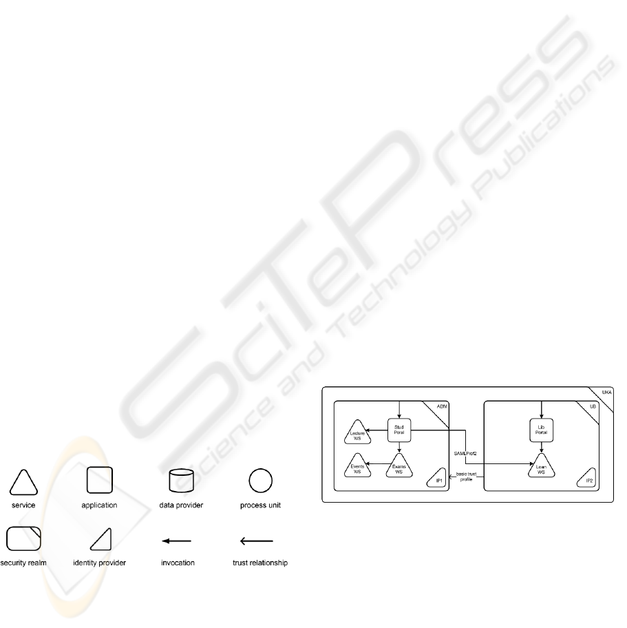
and paper fashion. Figure 2 contains the symbols of
the most important model elements. Further details
about the model, can be found in (Meinecke, Gaedke
et al. 2005; Meinecke, Gaedke et al. 2006)
Figure 2: Symbols for important WAM modeling
elements.
The security realm represents organizational
boundaries and with it the zones of control over the
owned Web-based systems. It is equipped with
exactly one designated security token service (STS).
This service acts as the source for the tokens
required to use the realm’s resources and is as such
the central authority for access control decisions. As
a counterpart to the STS, the identity provider (IP) is
a security token service specialized on
authenticating anonymous requestors. Based on the
authentication, the IP generates tokens that can then
be presented at the STS for authorization requests.
The services represent the distributed components
that are provided by the different involved federation
partners, usually in the form of SOAP Web services
that expose their functionality through a defined
WSDL interface. From the user point of view, the
interaction with the overall system takes place
through the interfaces provided by (Web)
applications. In addition to that, WAM also
addresses important system parts that are not directly
Web-capable. In cases where it is useful to
distinguish between a service and the underlying
component that serves as the actual data source, this
can be modeled with a separate data provider, like
e.g. databases and wrapped legacy systems. If a
connected system performs functionality beyond
data management, then it is represented with a
process unit symbol, like e.g. for an output
management solution that passes on messages via
mail or fax. Potential accesses on services and
applications are stated with invocation links. In order
to form federations, trust relationships can be
established between separate realms. Semantically,
this extends the area of validity of the trusted
realm’s security tokens to the trusting realm. In this
context, the STS acts as a gateway that accepts
foreign tokens and maps them to locally valid
claims, based on a set of pre-defined rules.
Figure 3: WAM example scenario.
As an example, Figure 3 contains the design of
two federated university Web portals for students
and library users. Both portals provide their content
with the help of Web services, with Stud Portal also
integrating the functionality of a service from the
other realm. This is enabled by the trust relationship
running in the opposite direction. As an additional
form of cooperation, this setup also allows students
that have already logged in at realm ADM to perform
WEBIST 2007 - International Conference on Web Information Systems and Technologies
18

tasks at the portal in realm UB without any
additional authentication steps (single sign on).
3.3 Specification of Technical Details
As the application of the model to real-world
scenarios has shown, it often becomes necessary to
include characteristics of the system that are difficult
to express in visual-only notations. For example, the
Web service protocols cannot always be referred to
by a simple label like “SOAP over HTTP”, as there
exist a huge number of options concerning e.g.
cryptographic operations or ways of requesting and
passing on security tokens. A similar need for
annotation exists with respect to other modeling
elements, as e.g. trust relationships. We suggest
including such details in reusable profiles outside the
graphical notation, which are referred to from within
the diagrams by labels. As a first approach to profile
specification, we have applied the Object Constraint
Language (OCL) (Warmer and Kleppe 1999) in
correspondence to the way OCL supplements UML
diagrams. For example, referring to the invocation
label in Figure 3, an OCL constraint with security-
specific requirements to the service invocation can
make fine-grained statements about the signatures,
encrypted information and tokens included in the
SOAP message:
context SAMLProf2 inv:
soapTransport = “HTTPS” and
request.signed = true and
response.encrypted = true and
request.signature.key =
response.encryption.key and
request.tokens->exists( t:SAMLIdentityToken |
request.signature.key = t.requestorKey )
The formal basis for the OCL restrictions is
established by a metamodel providing the properties
of the modeling elements that can be put together to
form expressions (Meinecke, Gaedke et al. 2005).
4 WAM-XML LANGUAGE
The graphical notation of WAM focuses on
diagrams that are relatively easy to draw and
comprehend. As a means for documenting the
system’s architecture, they form the basis for
communicating the models between stakeholders,
e.g. during the design process. Later at operation
time, the changes that inevitably affect the evolving
system cause the mentioned gap between the
modeled world and the model. While OCL
expressions help humans to add system details that
are also relevant for the implementation at runtime
(e.g. protocol restrictions), their complex syntax
render them inappropriate for further machine-based
processing, automation and code generation. Instead,
we designed a language that is capable of describing
the modeling concepts from the previous section,
and at the same time forms the basis for tools and
support systems. The language (called WAM-XML
in the following) is implemented as an application of
the XML, and as such profits from its manifold
capabilities, especially in the context of large-scale
heterogeneous systems. WAM-XML addresses both
the standard WAM elements and supports multiple
modeling layers. Hence, a corresponding XML
document may contain model instances from
different layers at the same time. Documents with
models that are related to each other can also be
aggregated to more comprehensive representations
of the overall system.
The definition of the XML notation is given in
the form on an XML schema, which incorporates
existing XML-based specifications where
appropriate to improve the overall interoperability
and the applicability of standard tools. For example,
WAM-XML comprises a metadata concept that is
based on the Dublin Core Metadata Initiative
(Andresen 2003), a de-facto standard defining a set
of common meta-level attributes. Moreover, the
realization of the WAM relationship concept makes
use of the XLink specification (DeRose, Maler et al.
2000) that describes standardized ways of linking
together resources in XML documents. To account
for the various applied standards, as well as for the
different parts of the WAM modeling framework,
WAM-XML divides the defined XML attributes and
elements into multiple namespaces. Thus, there is
one namespace for the modeling framework
(abbreviated with core in the following), a separate
one for the actual WAM concepts (wam), as well as
extra namespaces for the adopted standards Dublin
Core (dc) and XLink (xlink). In the case of custom
model extensions, new namespaces can be
introduced to clearly distinguish the additional
modeling layers from the pre-defined standard parts.
Consequently, tools that consume WAM-XML
documents only need to understand document parts
that correspond to a limited number of namespaces
and ignore the others.
As specified by the WAM modeling framework,
there is the common concept of the modeling
element in all WAM-compliant models. In the
schema, this is reflected by the core type Element,
from which all other modeling types must inherit
(1). As a result of this inheritance hierarchy, all parts
of the model can be tagged with the Dublin Core
MODELING AND MANAGING FEDERATED WEB-BASED SYSTEMS
19

properties defined by Element, allowing for uniform
ways of processing different constructs. The
required Identifier property for example contains a
Uniform Resource Identifier (URI) that can be used
to uniquely address a certain element. As a more
readable form of representation, the Title coincides
with the string that labels the symbols of most
modeling elements (e.g. the name of a security
realm).
<xs:complexType name="Element"> (1)
<xs:sequence>
<xs:element ref="dc:Identifier"/>
<xs:element ref="dc:Title" minOccurs="0"/>
<xs:element ref="dc:Creator" minOccurs="0"/>
<xs:element ref="dc:Date" minOccurs="0"/>
...
</xs:sequence>
</xs:complexType>
Representing the class of modeling elements that
link together different entities, the Relationship type
inherits from Element and adds further XLink-
compliant attributes (2). According to the XLink
specification, the resources to be connected are not
addressed directly, as e.g. by an identifier. Instead,
the from and to attributes contain XLink labels that
serve as placeholders for a separately declared group
of resources. For this purpose, the WAM-XML
schema includes the Selector type that can be used to
map a label to a URI, or even to multiple URIs, if
more than one selector is defined with the same
label. Typically, this URI takes the form of an
XPointer expression that describes the positions of a
set of XML elements. In addition to the standard
compliance, this approach has the advantage that the
same relationship can have multiple origins and
destinations (n:m relationships). For example, this
allows for a concise statement of the fact that all
realms in a model trust a dedicated central realm.
The addressed resources may reside in different
XML files, providing ways of distributing the model
on multiple documents, possibly owned by different
federation partners.
<xs:complexType name="Relationship"> (2)
<xs:complexContent>
<xs:extension base="core:Element">
<xs:attribute ref="xlink:type" fixed="arc"/>
<xs:attribute ref="xlink:from"
use="required"/>
<xs:attribute ref="xlink:to" use="required"/>
</xs:extension>
</xs:complexContent>
</xs:complexType>
<xs:complexType name="Selector">
<xs:attribute ref="xlink:type"
fixed="resource"/>
<xs:attribute ref="xlink:label" use="required"/>
<xs:attribute ref="xlink:href" use="required"/>
</xs:complexType>
Derived from the Relationship type, the Invocation
is an example of a concrete modeling element of the
WAM namespace (3). The corresponding schema
type declares properties that include the actual layer-
specific model information, in addition to the meta-
level information of the parent types. In this case,
this includes the underlying transport level protocol
applied to deliver the SOAP message, and
SOAPContext elements to describe SOAP-specific
restrictions to the request and response messages.
<xs:complexType name="Invocation"> (3)
<xs:complexContent>
<xs:extension base="core:Relationship">
<xs:sequence>
<xs:element name="SOAPTransport"
type="wam:SOAPTransportType"/>
<xs:element name="Request"
type="wam:SOAPContext" minOccurs="0"/>
<xs:element name="Response"
type="wam:SOAPContext" minOccurs="0"/>
<!-- ... -->
</xs:sequence>
</xs:extension>
</xs:complexContent>
</xs:complexType>
<xs:simpleType name="SOAPTransportType">
<xs:restriction base="xs:string">
<xs:enumeration value="http"/>
<xs:enumeration value="https"/>
<xs:enumeration value="smtp"/>
<xs:enumeration value="tcp"/>
</xs:restriction>
</xs:simpleType>
To demonstrate, how the schema types are
instantiated in WAM-XML documents, we show an
extract from an example model (4). The document
contains elements both from the WAM layer (wam),
as well as from the model extension (hst). In this
particular scenario, there is a Web service WS1 that
is hosted by a Web server labeled as Server1. This is
expressed with an inter-model relationship defined
within the hosting layer namespace.
<wam:Service> (4)
<dc:Identifier>
http://mwrg.tm.uka.de/ws1
</dc:Identifier>
<dc:Title>WS1</dc:Title>
...
</wam:Service>
<hst:System>
<dc:Identifier>
http://mwrg.tm.uka.de/server1
</dc:Identifier>
<dc:Title>Server1</dc:Title>
<hst:Type>WebServer</hst:Type>
...
</hst:System>
<hst:HostingRelationship
xlink:from="LabelS1"
xlink:to="LabelWS1">
<dc:Identifier>urn:wamid:C8B9...</dc:Identifier>
</hst:HostingRelationship>
<core:Selector xlink:label="LabelWS1"
xlink:href="xpointer(/core:Model/core:Body/*
[dc:Identifier='http:...'])"/>
<core:Selector xlink:label="LabelS1"
xlink:href="xpointer(/core:Model/core:Body/*
[dc:Identifier='http:...])"/>
WEBIST 2007 - International Conference on Web Information Systems and Technologies
20
As prescribed by the relationship concept, two labels
LabelWS1 and LabelS1 are declared, which in this
simple example can be directly mapped to one
XML-element each.The mapping is achieved with
an XPointer expression that uses the identifier
introduced by the Dublin Core metadata concept as a
unique key for addressing. Although the document
contains non-standard extensions, a tool developed
without any knowledge about the hst namespace
would still be able to process the rest of the
document, simply by ignoring any unknown
elements.
While the presented XML format is not necessarily
intuitive to write down manually, it provides a solid
basis for applications that work with the modeling
information at the operation time of the federated
system. With a similar expressiveness of both
representations, models can be transformed from one
into the other and vice versa.
5 WAM SERVICE
In the context of the overall goal to facilitate the
design and evolution of Web-based federations, the
existence of a machine-readable modeling language
is only a first step. Additionally, the modeling data
has to be exposed and made available within the
distributed solution, calling for the presence of a
supporting infrastructure. Our idea regarding this is
to apply the same technology that is already in use
for the functional parts of the architecture and
provide a Web service for querying and changing
the model. Similarly to a UDDI node, this
infrastructure service takes the role of a central
registry, at which the partners of the federation
publish their components and relationships. Unlike
UDDI, the entries are not related to the provided
functionality, but instead to the federation- and
access-control-specific aspects that is not covered by
UDDI.
The outlined WAM Service has been applied
within the service-oriented integration project KIM
conducted at the University of Karlsruhe (University
of Karlsruhe 2005). The scope of integration covers
11 faculties as well as cooperations with other
universities in the context of the Bologna Process
(European Union 2005), which supports the mobility
of students, teachers and researchers within the
European Union by introducing common quality
standards. As one of a group of infrastructure Web
services, the WAM service acts as a source of
architectural information about the growing network
of services provided by the different university
departments. This group includes a UDDI-based
service registry, a status log service providing the
health history of monitored resources, as well as
other third-party services. A common addressing
concept among the data objects of the infrastructure
services ensures that system information from
different sources can be related to each other. For
example, this allows for looking up an application
described in WAM and afterwards querying the
status log for health status information about that
same application.
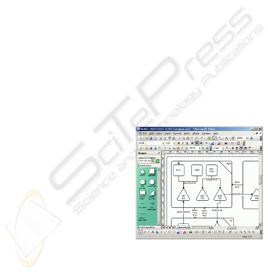
On top of the WAM infrastructure service, two
applications have been implemented that work
directly on the provided model information and have
successfully been deployed in several projects. As a
means for supporting model engineers in creating
and modifying system descriptions, we customized
Microsoft Visio with dedicated support for WAM
diagrams. The drag & drop interface editor (cf.
Figure 4) allows the placement of the pre-defined
model symbols and their annotation with additional
attributes, according to the data model presented in
the previous section. With the help of the XML-
support already built into Visio, we added an XSLT-
based transformation engine to generate WAM-
XML from the diagrams and write the resulting code
into the model database managed by the WAM
Service.
Figure 4: Diagram authoring support.
While the model in the database is being updated
manually with Visio or automatically through
additional support tools, it becomes important to
keep track of the ongoing changes within the
federation. One way to do this in a standardized
manner is to provide an RSS feed that serves as a
means for publishing events – in other words: the
MODELING AND MANAGING FEDERATED WEB-BASED SYSTEMS
21

federation is blogging about its existence. Thus, an
overview is provided of new services joining the
federation, changing trust relationships, the rerouting
of service invocations etc.
We consider the two presented applications as a
proof of concept for the approach to expose the
model via a service that is itself a part of the
federation it supports. The Visio-based diagram
authoring tool and other related infrastructure
components can be downloaded at
http://mwrg.tm.uni-karlsruhe.de/downloadcenter/.
6 CONCLUSION
We presented WAM as an approach to model the
architecture of federated Web-based applications
with a special focus on token-based access control
concepts. As key challenges to such a model, we
identified the need for integrating security aspects
into the model, for hiding unwanted complexity and
for linking the model close to the modeled evolving
system. The WebComposition Architecture Model,
is founded on token-based access control concepts
identified in current specifications. As a machine-
readable representation of WAM, an XML format
has been defined. This XML-based system
information is exposed through an infrastructure
Web service, on top of which tools can be built to
support federated applications at operation time.
One possible extension of the described work
would be the definition of a UML profile for WAM
to enable the applicability of standard UML
modeling tools. As mentioned, the machine-readable
model and the developed support service offer
potential for applications that go beyond the two
demonstrated tools. Therefore, in the future we will
add systems that provide a higher degree of
automation and code generation, like e.g. producing
configuration files for the participating services and
applications directly from the model.
REFERENCES
Andresen, L., 2003. Dublin Core Metadata Element Set,
Version 1.1: Reference Description, Dublin Core
Metadata Initiative (DCMI).
Bajaj, S., G. Della-Libera, et al., 2003. Web Services
Federation Language (WS-Federation). http://www-
106.ibm.com/developerworks/webservices/library/ws-
fed/ (14.10.2004).
Bass, L., P. Clements, et al., 1998. Software Architectures
in Practice. Reading, USA, Addison-Wesley.
Cameron, K., 2005. The Laws of Identity.
http://msdn.microsoft.com/library/en-
us/dnwebsrv/html/lawsofidentity.asp (29.10.2005).
DeRose, S., E. Maler, et al., 2000. XML Linking Language
(XLink) Version 1.0, World Wide Web Consortium.
European Union, 2005. The Bologna Process.
http://europa.eu.int/comm/education/policies/educ/bol
ogna/bologna_en.html (23.02.2006).
Gootzit, D. and G. Phifer, 2003. Gen-4 Portal
Functionality: From Unification to Federation.
Stamford, CT.
Hermanns, J., C. Jänsch, et al., 1999.
"Architekturmanagement im Großunternehmen."
OBJEKTspektrum(4/99).
Kappel, G., B. Pröll, et al., 2006. Web Engineering: The
Discipline of Systematic Development, Wiley.
Kirchner, L., 2005. Cost Oriented Modelling of IT-
Landscapes: Generic Language Concepts of a Domain
Specific Language. Workshop on Enterprise
Modelling and Information Systems Architectures
(EMISA ´05), Klagenfurt, Austria.
Liberty Alliance Group, 2004. Liberty Alliance
Specifications.
http://www.projectliberty.org/resources/specifications.
php (18.10.2004).
Maler, E., P. Mishra, et al., 2003. Assertions and Protocol
for the OASIS Security Assertion Markup Language
(SAML) V1.1. http://www.oasis-open.org/specs/
(18.10.2004).
Meinecke, J., M. Gaedke, et al., 2006. Capturing the
Essentials of Federated Systems. 15th International
World Wide Web Conference (WWW), Edinburgh, UK,
ACM.
Meinecke, J., M. Gaedke, et al., 2005. A Web Engineering
Approach to Model the Architecture of Inter-
Organizational Applications. Conference on
Component-Oriented Enterprise Applications (COEA
2005), Erfurt, Germany, Gesellschaft für Informatik.
Meliá, S. and C. Cachero, 2004. An MDA Approach for
the Development of Web Applications. 4th
International Conference of Web Engineering (ICWE
2004), Munich, Germany.
Microsoft, 2003. Dynamic Systems Initiative Roadmap.
http://www.microsoft.com/dsi (14.10.2004).
OASIS, 2004. Data Center Markup Language Framework
Specification. http://www.dcml.org/technical_info/
(03.11.2004).
Park, J. and S. Ram, 2004. "Information Systems
Interoperability: What Lies Beneath?" ACM
Transactions on Information Systems (TOIS) 22(4):
595-632.
SysML Partners, 2005. Systems Modeling Language
(SysML) Specification Version 0.9 Draft.
http://www.sysml.org/ (17.10.2005).
University of Karlsruhe, 2005. KIM Project Homepage.
http://www.kim.uni-karlsruhe.de/ (24.04.2005).
Warmer, J. and A. Kleppe, 1999. The Object Constraint
Language, precise modeling with UML. Reading,
Mass., Addison-Wesley Pub Co.
WEBIST 2007 - International Conference on Web Information Systems and Technologies
22
