
ON GENERATING TILE SYSTEM FOR A SOFTWARE
ARCHITECTURE CASE OF A COLLABORATIVE APPLICATION
SESSION
C. Bouanaka, A. Choutri
Department of Computer Science, Mentouri University, Constantine, Algeria
F. Belala
Department of Computer Science, Mentouri University, Constantine, Algeria
Keywords: Tile Logic, Software Architecture, Arch
itecture Description Languages, Synchronization, Dynamic
connection.
Abstract: Tile logic, an extension of rewriting logic, where synchronization, coordination and interaction can be
naturally expressed, is showed to be an appropriate formal semantic framework for software architecture
specification. Based on this logic, we define a notion of dynamic connection between software components.
Then, individual components are viewed as entirely independent elements and free from any static
interconnection constraints. We also fill out the usual component description, expressed in terms of
Provided/Required services, with functionalities specification of such services. Starting from
State/Transition UML diagrams, representing requirements of the underlying distributed system, our
objective consists of offering a common semantic framework for architectural description as well as
behavioural specification of that system. Direct consequences of the proposed approach are dynamic
reconfiguration and components mobility which become straightforward aspects. A simple, but
comprehensive, case study, the collaborative application session, is used to illustrate all stages of our
proposed approach.
1 INTRODUCTION
With computer science revolution, software
applications become more complex and constantly
evolving, their development requires more labour
and needs increasing cost. The main difficulty in
specifying distributed software systems is due either
to the great number of entities composing it or to the
difficulty in specifying interactions, coordination
and synchronization among parts of the system. A
direct consequence is that system global structure,
its software architecture, became a central problem
of conception.
The system software architecture is a form
of
contract showing the intended correspondence
between system requirements and components of the
designed system. It may be ensured all over the
ongoing stages of software engineering.
Consequently, a system specification may be viewed
as a sequence of refinements starting from its
abstract software architecture, defined as a set of
communicating black boxes, until obtaining the
more detailed behaviour of each component.
One challenging approach is to specify an ADL
sem
antics allowing system architecture description
as a set of black boxes related via an interconnection
topology and offering necessary tools to obtain
transparent boxes where internal behaviours can be
specified.
In this work, we use Tile logic (Bruni, 1999), an
ex
tension of rewriting logic (Meseguer, 1992), as a
common semantic framework to define abstract
software architectures and their behaviours.
Our contribution consists of providing a tile
l
ogic based architecture description model for
distributed application. Such architecture is defined
as a set of independently executing components with
a dynamic interconnection topology. Each
component is defined as a set of external ports, to
ensure interactions with the environment, and an
internal behaviour operating on its basic structure.
123
Bouanaka C., Choutri A. and Belala F. (2007).
ON GENERATING TILE SYSTEM FOR A SOFTWARE ARCHITECTURE CASE OF A COLLABORATIVE APPLICATION SESSION.
In Proceedings of the Second International Conference on Software and Data Technologies - SE, pages 123-128
Copyright
c
SciTePress

Thus, two views are considered for each component:
black view defines its observable behaviour in terms
of interactions, while transparent view specifies its
detailed behaviour.
Based on state/ transition UML diagram, a tile
system is generated for each component, transparent
view, to describe both internal structure and
behaviour. At higher description level, composition
of all component tile systems is enriched with a set
of synchronization tiles to define all possible
dynamic connections while considering each
component as a black box. Dynamic connection is
ensured by a unique generic synchronization tile
which: (1) creates a connection between the sender
component and the receiver one by duplicating the
output port of the former, (2) transfers port content
by swapping one copy of the output port of the
sender and the input port of the receiver, and (3)
ends the interaction by destroying (discharging) the
empty port.
The remainder of the paper is organized as
follows. Section 2 compares the proposed approach
to other existing ADLs. Section 3 presents the basic
semantic aspects of Tile Logic. Section 4 is devoted
to our proposal. It presents main ideas introduced on
software architectures description, while section 5
illustrates them via a collaborative session case
study. Discussion and conclusions round out the
paper.
2 RELATED WORKS
A great number of ADLs have been proposed in the
literature. However, most of them: Wright (Allen,
1997), Rapide (Luckham, 1995), Darwin (Magee,
1995), etc., focus on the software architecture
description where component semantics is in part
expressed by its interface, and system behaviour is
not completely defined (Megzari, 2004). Therefore,
software architecture concepts need to be associated
to formal theories, clarifying these concepts or
providing rules to determine whether a given
architecture is well-formed.
In our proposal, a software architecture,
designed to facilitate designers job, is systematically
transformed to a formal theory specification, which
can be prototyped or model checked. This facilitates
the integration of formal specifications in the
traditional life-cycle of an application development.
We present an interesting combination of Tile logic,
an extension of rewriting logic, and Software
Architectures. Some works were already done in this
direction. In (Clavel, 1999), authors specify the
semantics of several typical architectural patterns in
rewriting logic. In (Bragal, 2003), authors provide a
mapping of Cbabel ADL concepts in rewriting logic.
CommUnity (Bruni, 2004) is another ADL whose
semantics was defined in Tile Logic (Bruni, 1999).
Authors’ objective was to show how these two
models (Tile logic and CommUnity) contribute to
characterize software architectures. They define a
mapping of CommUnity programs into Tile Logic.
Their work gives rise to some complexity
particularly during the decomposition phase of a
CommUnity program. Our approach is
complementary to all these researches since it
defines a Tile logic based model of ADLs. It
considers system software architecture as a set of
black boxes interconnected via a dynamic
interconnection topology. It also allows defining
alternative transparent boxes where internal
behaviours can be formally specified.
3 TILE LOGIC
Tile logic (Bruni, 1999) is an extension of rewriting
logic (in the unconditional case) taking into account
rewriting with side effects and rewriting
synchronization. Ordinary rewrite rules format
expressing naturally state changes and concurrent
calculus. However, they lack tools to express
interactions with the environment; they can be freely
instantiated with any term in any context. The main
idea of Tile Logic is to impose dynamic restraints on
terms to which a rule may be applied by decorating
rewrite rules with observations ensuring
synchronizations and describing interactions. The
resulting rewrite rule is called a tile.
A tile α has the graphical representation in figure
1, also written s
b
a
⎯
⎯→
t, stating that the initial
configuration s can evolve to the final configuration
t via
α
, producing the effect b, which can be
observed by the environment. Such step is allowed
only if the arguments (subcomponents) of s can
contribute by producing a, which acts as a trigger of
α
. Triggers and effects are called observations; tile
vertices are called interfaces (Gadducci, 1997).
Final Output
Interface
Initial Output
Interface
Initial Input
Interface
Final Input
Interface
x
y
w
z
a
b
s
t
α
Figure 1: Graphical Representation of a Tile.
A set of tiles is defined to describe the behaviour
of partially specified components (i.e., containing
variables) called configurations.
ICSOFT 2007 - International Conference on Software and Data Technologies
124

A configuration is expressed only in terms of
possible interactions with the inside and outside
environment and system behaviour is viewed as a
coordinated evolution of its local configurations.
Definition (Bruni 99): A tile system is a 4-tuple
R = (H, V, N, R) where H, V are monoïdal categories
with the same set of objects O
H
= O
V,
N being a set
of rule names and R: N→ H x V x V x H a function
where for each α in N, if R(α) = (s,a,b,t), then
s:x
→
y, a: x
→
z, b:y
→
w and t: z
→
w, for suitable
objects x, y, z and w, x and z are the input interfaces.
While, y and w are the output interfaces.
Arrows of H and V are called configurations and
observations respectively while their objects are
called interfaces.
R is a set of tiles expressing all basic local changes
on configurations according to the occurrence of
some observations. It defines local possible
evolutions of the system.
Tile logic exploits a three-dimensional view of
concurrent systems: horizontal dimension (space)
models coordination of components according to the
structure of the system, vertical dimension (time)
models state evolutions according to computation
flows, while the third dimension (parallel) models
distribution of activities and resources.
Configurations and observations are algebraic
structures equipped with parallel and sequential
operators (⊗ and ; operators respectively) to allow
building of larger components.
A standard set of deduction rules indicates how
to build up larger steps, starting from basic tiles of
the system, via horizontal, vertical and parallel
compositions (see Figure 2).
Rules generating the basic tiles:
() ,,,
:
a
b
Rsabt
st
α
α
=
⎯⎯→
Rules generating the horizontal and vertical
identities:
:
:
V
a
a
ax z V
id x z
→∈
⎯⎯→
:
:
H
x
y
tx y H
id t t
→∈
⎯⎯→
Horizontal, vertical and parallel compositions
c
d
;
;
: :t
:
a
b
ac
bd
st h
sh
αβ
αβ
⎯⎯→⎯⎯→
•⎯⎯→
b
c
: :hf
: ;h t;f
a
b
a
c
st
s
αβ
αβ
⎯⎯→⎯⎯→
∗⎯⎯→
c
d
: :hf
:tf
a
b
ac
bd
st
sh
αβ
αβ
⊗
⊗
⎯⎯→⎯⎯→
⊗⊗⎯⎯⎯→⊗
Figure 2: Deduction Rules of Tile Logic.
If some interface rearrangements (duplications,
projections, swaps) are necessary, auxiliary tiles can
be added to the system and composed with the
identity and basic tiles.
Tile logic offers a flexible formal framework
(meta-formalism) to specify rule-based
computational systems behaviour like reactive
systems, open systems, coordination languages,
concurrent systems, mobile calculi (Bruni, 2003),
(Ferrari, 2000). In addition, tile logic benefits on all
software tools (Maude environment) (Clavel, 2003)
offered by rewriting logic to obtain executable
specifications.
4 MAIN CONTRIBUTION
A reactive view of concurrent systems is possible in
tile logic, since components can be conceived
separately and then composed via their behaviours.
Such a view corresponds to a software architecture
view of a distributed system very loosely. Therefore,
we propose a novel view of software architecture,
independent from the interconnection topology.
Moreover, components are viewed as floating
elements since a static interconnection topology
definition, like in most of existing ADLs, is
completely absent. We also fill out the usual
component description, expressed in terms of
Provided/Required services, with functionalities
specification of such services. Hence, each
component will be described by a set of external
ports, ensuring interactions with the
environment, and an internal behaviour, specified by
a tile system, to deliver system functionalities. We
can obtain similar results in rewriting logic.
However, rewriting logic lacks tools to express
synchronization aspects. Tile logic main
contribution is a formal specification of possible
synchronizations between components.
Traditionally, this kind of synchronization is defined
by static connectors. In our work, we propose a tile
based dynamic connector.
Concretely, the dynamic connection depends on
the contribution of two components to execute a
shared action (synchronization), expressed by a tile.
When a send action (trigger of the tile) is initiated by
the sender, the synchronization tile takes place and
plays the role of a dynamic connection.
Synchronazation:
() () ()
() () () '(),() () () '()
(()) ;
;;!
() () () '()
in y C x C y
out x in y out x in y in y out x in y in y
Send out x id id id
id id id id
Cx Cy cx c y
γ
⊗⊗
∇⊗ ⊗ ⊗⊗
⊗ ⎯⎯⎯⎯⎯⎯⎯⎯⎯⎯⎯⎯⎯⎯⎯→⊗
Figure 3: Dynamic Connection Tile.
ON GENERATING TILE SYSTEM FOR A SOFTWARE ARCHITECTURE CASE OF A COLLABORATIVE
APPLICATION SESSION
125
Synchronization tile is parameterized by C(x)
and C(y), which are the sender (x) and receiver (y)
configurations. out(x) and in(y) are output and input
ports of the sender component and receiver one
respectively. Message receipt by y changes its
configuration to C’(y), since in(x) object value has
been modified. Synchronization tile is triggered by a
send action. It starts by preparing interaction
necessary interfaces (isolates out(x) and in(y) thanks
to parallel composition of horizontal identities id
C(x)
and id
C(y)
). Synchronization tile effect is the
following sequence: A connection Creation (∇
operator) between the sender component and the
receiver one. A transfer of out(x) port contents by
swapping (γ operator) one output port copy of the
sender and the receiver input port. Then, interaction
end by discharging (! operator) the empty port. We
notice that, duplicator operator ∇ creates a copy of
the sender output port and renames it as in’(y).
5 CASE STUDY
Distributed collaborative applications are
characterized by supporting groups’ collaborative
activities. This kind of applications is branded by
physically distributed user groups, who cooperate by
interactions and are gathered in work sessions
(Molina, 2003). The effective result of collaboration
in a session is a production of simultaneous and
concurrent actions. Interactions are fundamental
actions of a collaborative session and require being
coordinated (synchronized) to avoid inconsistencies.
We consider a simplified version of collaborative
session where session management is not treated
since we are more interested on synchronization
aspects and their definition in tile logic.
5.1 Software Architecture of the
Collaborative Application
Software architecture of a collaborative session is
composed of one president and several instances of
participant component (see Figure 4).
Port 1
President
: Dynamic Connection
Port n
Port 2
Port
Partici
p
ant 1
Port
Participant 2
Port
Participant n
: A pair of (in/out)
ports
Figure 4: Software Architecture of a collaborative Session.
President component interact with each
participant component via a pair of (in/out) ports. A
connection (dashed line) between (in/out) port of the
president and (out/in) port of a participant is
established dynamically if needed.
5.2 Components Tile Systems
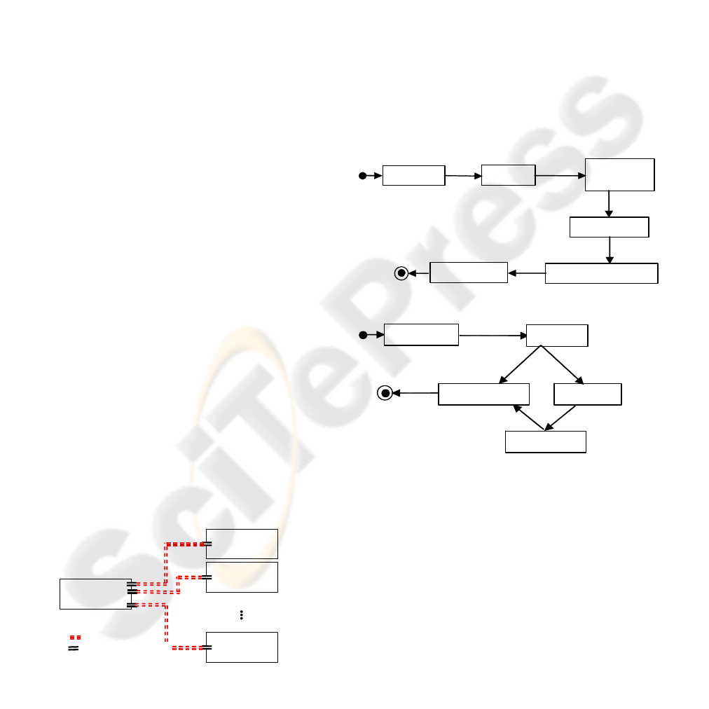
Figure 5 illustrates a president and any participant
behaviour. To open a session, the president begins
by announcing it. He prepares an invite message and
broadcasts it all participants. The session is opened
by the president when at least a positive response
(accept to participate) is received. Participants are
then informed by an open message. Managing
session consists of realizing the collaborative task
with contribution of all session members. When the
collaborative task is terminated, the president closes
the corresponding session by sending a close
message to all participants.
Prepare
Close
Announce
Inviting
Wait-
Response
End-Session
Open-Session
Session-Management
Receive-Response
Pr-Ready
Inform
(a) President Diagram
Reject
Receive-Close
Disconnected Expected
Connected
Receive-Invite
Par-Ready
Invited
Accept
(b) Participant Diagram
Figure 5: State / Transition diagrams.
5.2.1 Horizontal and Vertical Categories
Objects of the two categories define component
internal structure. Vertical category (observations)
of a component defines its possible actions, i.e.,
provided services of the component. Morphismes of
the vertical category specify possible actions on
objects. Horizontal category (configurations) of a
component defines component possible states.
Gathered together via a set of tiles, horizontal and
vertical categories define the expected behaviour of
ICSOFT 2007 - International Conference on Software and Data Technologies
126

the underlying component. Based on diagrams
presented below, one can identify configurations
(states) and observations (actions) of each
component. In what follows, we will present tile
system associated to the president only. In a similar
way, tile system associated to a participant
component can be generated. Due to space
limitation reasons, it is omitted.
1) Objects: Identified objects for the president
are:
- Port: we associate a port to each participant
communicating with the president,
- Participant-List: each entry in the list
corresponds to a participant and indicates its state
(Connected/Disconnected),
- Buffer: contains received messages,
- Msg: a message to send.
2) Configurations: Corresponds to the identified
states of the president component in Figure 5(a).
Each configuration is a 4-uplet (ports, l, b, m),
where:
Ports is a n-uplet of pairs (in/out) of ports with n is
the number of participants, l is of sort Participant-
List, b is a buffer and m is of sort Msg.
For simplicity reasons, we use the following
notations:
-Empty =
1
(,
n
i
)
E
mpty Empty
=
∏
: to denote that all
(in/out)ports are empty,
- Outs = : an n-uplet of all output of the
president,
1
(( ())
n
i
out port i
=
∏
-full-in(i,m)= :
indicates a message deposit on the i
1
11
( ( ), ( )),( , ( )), ( ( ), ( ))
in
jki
in j out j m out i in k out k
−
==+
∏∏
th
(in)port,
-empty-in(i)= :
expresses that a the i
1
11
( ( ), ( )),(0, ( )), ( ( ), ( ))
in
jki
in j out j out i in k out k
−
==+
∏∏
th
(in)port is empty,
-full-outs(m)=
1
: a massage deposit on all
participants (out)ports,
((),)
n
i
in i m
=
∏
- init-list : generates an empty list.
Basic configurations correspond to the president
diagram states. Starting from the initial
configuration Pr-Ready, which corresponds to the 4-
uplet (empty, init-list, empty, empty), the president
can evolve to the following configurations:
- Wait-Response = (Outs, init-list, empty, msg-
invite): the president has sent an msg-invite and is
waiting for a response,
- Open-Session = (Outs, l, empty, msg-open) :
the president has sent an msg-open message to all
participants (Outs term of the configuration),
- Session-Management = (ports, l, b, m): the
president is realising the collaborative task with the
n participants,
- End-Session = (Outs, l, b, msg-close): a msg-close
is broadcasted to all participants.
3) Observations: We present a subset of
observations sufficient to explain our approach:
- deposit(x:Msg) = full-outs(x) : deposit a message
on a all its (out)ports,
- send(x:port) : sends an out(port) content,
- :
corresponds to a broadcast action of the deposited
message to all participants.
1
() ((())
n
i
Send all Outs send out port i
=
−=⊗ )
- receive(i) (x:ports, y:Msg) = full-in(i,y) : indicates
a message receipt on the i
th
port,
consume(i)(x:ports,y:list)=(empty-in(i),update-
list(y,i)) a response withdrawal from port i and an
update of participant-list.
We note that participant component manipulates:
a status (Disconnected, Invited, and Connected), a
pair of ports (in/out), a buffer and message. Thus its
configurations are 4-uplet (st, p, b, m).
5.2.2 Tiles
The expected behaviour of the president is specified
with a set of tiles. We present here tiles
corresponding to session open and session close
only:
Prepare:
(,)
Re
id
deposit msg invite outs
Pr ady Inviting
−
− ⎯⎯⎯⎯⎯⎯⎯→
Announce:
()
id
Send all Outs
I
nviting Wait Response
−
⎯⎯⎯⎯⎯→−
Response-Receipt:
Inform:
Close:
((), )
(( ()),); ( , )
receive port i msg Accept
consume in port i l deposit msg open outs
Wait Response Open session
−
−
− ⎯⎯⎯⎯⎯⎯⎯⎯⎯⎯⎯⎯⎯→−
(,)
()
deposit msg Open outs
Send all Outs
Open session Session Management
−
−
− ⎯⎯⎯⎯⎯⎯⎯→ −
(,)
()
deposit msg close Outs
Send all Outs
Session Management End Session
−
−
− ⎯⎯⎯⎯⎯⎯⎯→ −
5.3 Synchronization between
Components
An interaction between the president and a
participant component corresponds to the dynamic
connector tile execution by instantiating C(x) and
C(y). As an example, the president puts an msg-
ON GENERATING TILE SYSTEM FOR A SOFTWARE ARCHITECTURE CASE OF A COLLABORATIVE
APPLICATION SESSION
127

invite message in all output ports by executing its
Prepare
tile. Then, he sends the message by
executing Announce tile. President state evolves to
Wait-response. Announce effect is a broadcast of
msg-Invite to all participants, which actually do
nothing (Ready state). It triggers the synchronization
tile. Instantiations are as follows:
- x = the president, y = a participant,
- C(x)
⊗
C(y) = Wait-Response
⊗
Par-Ready.
- The resulting configuration is C(x)
⊗
C(y) =
Wait-Response
⊗
Invited, since the input port of the
corresponding participant contains an msg-Invite
now. We obtain the following tile: synchronization:
()() ()
() () () '(),() ()() '()
(()) ;
;;!
Wait-Response Ready Wait-Response Invited
in part C pr C part
out pr in part out pr in part in part out pr in part in part
Send out pr id id id
id id id id
Par
γ
⊗⊗
∇⊗ ⊗ ⊗ ⊗
⎯⎯⎯⎯⎯⎯⎯⎯⎯⎯⎯⎯⎯⎯⎯⎯⎯⎯⎯⎯⎯⎯⎯⎯⎯⎯⎯⎯⎯⎯→⊗− ⊗
where pr denotes the president component and par
denotes a participant component.
6 CONCLUSION
In this paper, we showed how tile logic can be used
as a common semantic framework for architectural
and behavioural descriptions of distributed systems.
Starting from a Place/Transition UML diagrams,
describing the intended behaviour of the system, we
identify basic components and possible
interconnections between them via (in/out) ports. It
constitutes the architectural description phase or
black box view of the underlying system. Such view
is then refined by opening the black boxes and
glancing at their internal structure and behaviour. A
tile system is associated to each component. It
defines inherent objects and possible actions
(observations) on them. It also defines possible state
evolutions of component in terms of tiles. We have
also proposed a notion of dynamic connection in
software architectures. Dynamic reconfiguration and
mobility of components are straightforward
consequences of such component freeness from
static interconnection constraints and become
implicit aspects.
In our ongoing work, we plan to integrate some
ADLs in tile logic to ensure that our current
proposition is generic enough to cover a wide range
of distributed systems. We will also focus on
expressing inherent concepts of software
architectures (dynamic reconfiguration, component
mobility and non-functional properties of distributed
systems).
REFERENCES
R., Allen, 1997. “A Formal Approach to Software
Architecture.” PhD Thesis, Carnegie Mellon
University, CMU Technical Report CMU-CS-97-144.
C. Braga1, A. Sztajnberg, 2003, "Towards a Rewriting
Semantics for a Software Architecture Description
Language", in: A. Cavalcanti and P. Machado, editors,
Proceedings of WMF 2003, 6th Workshop on Formal
Methods, Campina Grande, Brazil, Electronic Notes in
Theoretical Computer Science 95, p.148-168.
R., Bruni, 1999. “Tile Logic for Synchronized Rewriting
of Concurrent Systems”, Phd Thesis, University of
Pisa, TD-1/99.
R., Bruni,, J., Meseguer, U., Montanari, 2003. “Tiling
Transactions in Rewriting Logic”, in ENTC, Vol.
71, 20 pp. 20-35.
R., Bruni, J. L., Fiadeiro, I., Lanese, A., Lopes, U.,
Montanari, 2004. “New Insight into the Algebraic
Properties of Architectural Connectors”, IFIP TCS, pp.
367-380.
M. Clavel, F. Duran, S. Eker, N. Martı-Oliet, P. Lincoln, J.
Meseguer, and J. Quesada, 1999. Maude: Specification
and Programming in Rewriting Logic. SRI
International, http://maude.csl.sri.com, January 1999.
M., Clavel, F., Duran, S., Eker, N., Marti-Oliet, P.,
Lincoln, J., Meseguer, C. Talcott, 2003. “Maude 2”,
SRI International and University of Illinois at Urbana-
champaign,
http://maude.cs.uiuc.edu.
G. L, Ferrari, U., Montanari, 2000. “Tile Formats for
Located and Mobile Systems”, Informatica
and.Computing, Vol.156, pp. 173–235.
F., Gadducci, U. Montanari, 1997. “The Tile Model”, in:
G. Plotkin, C. Stirling, and M. Tofte, Eds, Proof,
Language and interaction: essays in honour of Robin
Milner, MIT Press, to appear.
D. C., Luckham, J. J., Kenny, L. M., Augustin, J., Vera,
D., Bryan, W., Mann, 1995. “ Specification and
Analysis of system Architecture Using Rapide.” IEEE
Transactions on Software Engineering, vol. 21, no. 4,
pp. 336-355.
J., Magee, N., Dualy, S., Eisonbach, J., Kramer, 1995.
“Specifying Distributed Software Architectures.”, In
Proceedings of the Fifth Symposium on the
Foundations of Software Engineering (FSE4).
K., Megzari, 2004. “R EFINER: Environnement logiciel
pour le raffinement d’architectures logicielles fondé
sur une logique de réécriture.”, Thèse de doctorat en
Informatique. Université Savoie.
J., Meseguer, 1992. “Conditional Rewriting Logic as a
unified model of concurrency”, Theoretical Computer
Science, pp.73-155.
J. M., Molina Espinosa, 2003. “Modèles et services pour
la coordination des sessions coopératives multi-
applications: application à l’ingénierie systèmes
distribués”, Thèse de doctorat en Informatique et
télécommunications, LAAS of CNRS, Toulouse.
ICSOFT 2007 - International Conference on Software and Data Technologies
128
