
BELL SHAPED IMPEDANCE CONTROL TO MINIMIZE JERK
WHILE CAPTURING DELICATE MOVING OBJECTS
Arjun Nagendran, Robert C Richardson
School of Computer Science, University of Manchester, Manchester, United Kingdom
William J. Crowther
School of Mechanical, Aerospace & Civil Engineering, University of Manchester, Manchester, United Kingdom
Keywords: Catching, Impedance Control, Minimum Jerk, Bell Shaped Acceleration.
Abstract: Catching requires the ability to predict the position and intercept a moving object at relatively high speeds.
Because catching is a contact task, it requires an understanding of the interaction between the forces applied
and position of the object being captured. The application of force to a mass results in a change in
acceleration. The rate of change of acceleration is called jerk. Jerk causes wear on the manipulator over time
and can also damage the object being captured. This paper uses a curve that asymptotes to zero gradient at
+/- infinity to develop an impedance controller, to decelerate an object to a halt after it has been coupled
with the end effector. It is found that this impedance control method minimizes the jerk that occurs during
capture, and eliminates the jerk spikes that are existent when using spring dampers, springs or constant force
to decelerate an object.
1 INTRODUCTION
A catch can be defined as the entire process of
intercepting a moving object (by a manipulator),
wherein the object becomes attached to the
manipulator, and decelerating the object to bring it
to a halt. Catching in robotics is an important task
since it is an extension to being able to pick up
stationary objects. Catching has a wide variety of
application areas including manufacturing industries,
sports and space robotics. The ability to consistently
catch objects can be useful in certain sports like
baseball for repeated pitching practice. Catching a
ball using a baseball glove (Riley and Atkeson,
2002) and juggling and catching balls (Sakaguchi
et. al, 1991, Beuhler et. al 1994) have been studied
previously. Burridge et. al (1995), provide an insight
into dynamical pick and place robots. This can be
useful in picking moving objects randomly from
conveyor belts. Most of the literature on catching
describes trajectory planning and interception of the
object before the catch. The catch itself is generally
thought to be an inelastic collision. Minimizing
impact during capture and regulating the forces
thereafter is important to limit damage to the object.
The task of capturing a moving object by robotic
manipulators presents significant difficulties. The
process involves being able to accurately predict the
moving object’s position in time and move the
manipulator to the position where it can intercept the
object (Sakaguchi et. al, 1991). Once the object has
been intercepted, it becomes a part of the
manipulator (Kovecses et. al, 1999) and hence, the
dynamics of the manipulator change. These need to
be taken into consideration during the post-capture
phase. It is required to decelerate the object within
the allowable workspace of the manipulator (Lin et.
al, 1989) to prevent mechanical damage to the
system. At the same time, care must be taken to
decelerate the object within its permissible limits.
During the capture phase, a certain amount of
impact occurs depending on the mismatch in
velocities of the manipulator and the moving object.
Yoshikawa et. al (1994) present a relationship
between the relative velocities between moving
objects and the resulting impulse forces and go on to
calculate the optimum attitude of arms to minimize
mechanical shock. Once the object has been
captured, the kinetic energy of the object must be
dissipated as work done. This is achieved by
decelerating the object over a certain distance. There
504
Nagendran A., C Richardson R. and J. Crowther W. (2007).
BELL SHAPED IMPEDANCE CONTROL TO MINIMIZE JERK WHILE CAPTURING DELICATE MOVING OBJECTS.
In Proceedings of the Fourth International Conference on Informatics in Control, Automation and Robotics, pages 504-509
DOI: 10.5220/0001627105040509
Copyright
c
SciTePress

are several methods of decelerating an object after
capture. A well known method is the use of damped
springs. Constant force or springs can also be used
in order to perform the same task. The force profile
used (models of spring dampers, springs or constant
force) is crucial in determining the deceleration and
jerk experienced by the object.
During the process of catching, position control
of the manipulator is an important task. Although
position control can be used to move a manipulator
to intercept the object, this alone is insufficient to
successfully capture the object. While decelerating
the object, it is important to take into account, both
the position of the manipulator with respect to its
workspace and also the force being applied to
decelerate the object. Hogan N (1985) in his three-
part paper presents an approach to control the
dynamic interaction between the manipulator and its
environment. The author states that control of force
or position alone is insufficient and that dynamic
interaction between the two is required. This is
referred to as Impedance Control. Applying force
depending on time is inappropriate since it does not
ensure that the object is stopped over a certain
distance. By applying a force, depending on the
position of the object, the method ensures that the
moving body is brought to a halt by removing it’s
kinetic energy over a certain distance.
The first derivative of acceleration is called jerk.
Jerk is undesirable as it increases the rate of wear on
the manipulator and can also cause damage to the
object being captured. It is known to cause vibration
and is a measure of impact levels that can excite
unmodelled dynamics. This effect is more evident in
delicate or flexible structures (Muenchhof and
Singh, 2002, Barre et. al, 2005). It has been stated
(Kyriakopoulos and Saridis, 1991) that jerk
adversely affects the efficiency of the control
algorithms and joint position errors increase with
jerk. P Huang et. al (2006) in their work state that
jerk affects the overall stability of the system and
also causes vibrations of the manipulator and hence
must be minimized. Macfarlane and Croft (2001)
state that jerk limitation results in improved path
tracking, reduced wear on the robot and also results
in smoothed actuator loads.
In this paper, we assume that the process of
tracking and intercepting an object has been
completed. We then analyze the use of springs,
spring dampers and constant force in decelerating
the object during post-capture (once capture has
occurred). It is found that these methods result in a
high jerk. Hence a method to decelerate an object
over a certain distance keeping the jerk to a
minimum is proposed. The method establishes a bell
shaped impedance relationship between force and
position. The results of this method are then
compared to the other methods.
2 CAPTURE METHODS
A moving object has a certain amount of kinetic
energy associated with it. This is dependant on the
mass of the object and its velocity. For a body of
mass ‘m’ kg, travelling with a velocity ‘v’ m/s, the
kinetic energy is given by:
Kinetic Energy = ½ m v
2
(1)
In order to bring the object to rest, a certain
amount of force must be applied in a direction,
opposite to that of the motion of the object. For the
object to completely come to rest, it is required that
the amount of work done be equal to the kinetic
energy of the object. The work done is given by:
Work Done = Force * Displacement (2)
Equating (1) and (2),
Force * Displacement = ½ m v
2
(3)
Using equation (3), the force required to
decelerate an object over a certain distance can be
worked out. This however is a constant force. As the
distance over which the object must be decelerated
to a halt becomes small, the amount of force to be
applied becomes large and vice versa. Since force is
directly proportional to acceleration (from Newton’s
equation F = m * a), it follows that the deceleration
experienced by an object is greater when the object
is brought to a halt over a shorter distance than over
a longer distance. Hence, if the maximum
deceleration tolerable by a body is known, the
distance over which it can be brought to a halt by
applying a certain amount of force can be worked
out using equation (3). To decelerate the body, force
can be applied in different ways. Although force
control alone is sufficient to decelerate the object, it
is important to take into account, both the position of
the object and the force being applied to it (Hogan,
1985). An impedance controller can be used wherein
the output force is dependant on the position of the
object. This ensures that the amount of deceleration
experienced by the object at any position can be kept
within predefined limits. Impedance control requires
measuring the position of the object, and applying a
force depending on the desired impedance. The
desired impedance determines the amount of force to
be applied depending on the object’s position. The
BELL SHAPED IMPEDANCE CONTROL TO MINIMIZE JERK WHILE CAPTURING DELICATE MOVING
OBJECTS
505
amount of force applied controls the position of the
object, thus establishing a dynamic relationship
between force and position. Although the term
impedance control is usually associated with spring
damper response, in a broader sense, the desired
impedance can be a constant force, a spring or a
spring damper.
3 SIMULATION
The dimensional parameters used in the simulation
are mass, velocity and distance. We define the
following dimensionless variables in order to
perform non dimensional analysis of the results:
s
x
x =
ˆ
;
s
mv
F
F
2
ˆ
=
;
s
v
a
a
2
ˆ
=
;
2
3
ˆ
s
v
j
j =
(4)
where x is displacement, s is total distance over
which body decelerates, m is mass, v is velocity, F is
force, a is acceleration and j is jerk.
To compare the above impedance control
methods a simulation model was built using Visual
Nastran 4D software. This was interfaced to a
simulink model of the impedance controller. It
involves an object of mass 5 kg, moving with a
velocity of 5m/s. It is assumed that the object has
been successfully intercepted and coupled to the end
effector. A linear actuator is used to decelerate the
object. The impedance controller varies the amount
of force exerted by the linear actuator depending on
the position of the moving object (and the force
model – spring. etc). In order to make a fair
comparison of the different impedance controllers, it
was decided to decelerate the object to a halt over a
fixed distance of 2m. The results for each of the
methods are discussed below.
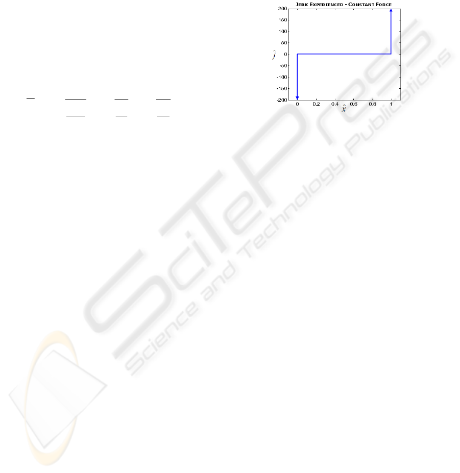
3.1 Jerk Analysis - Constant Force
The first model of the impedance controller was
designed to exert a constant force to decelerate the
object. Because the desired impedance is a constant
force irrespective of the position, the requirement for
a feedback loop is eliminated. The constant force
required was worked out using equation (3). For the
chosen values of mass (5kg) and velocity (5m/s), the
kinetic energy of the object is 62.5Nm. The distance
over which the object must decelerate is given to be
2m. Hence using (3), the force required is 31.25N.
This constant force was applied to the moving object
in the simulation. When constant force is used to
decelerate the vehicle, the sudden application of
force at the point of contact and also the sudden
removal of force at the end, result in a jerk. A graph
of
x
ˆ
against j
ˆ
is shown in Figure 1. The spikes at
the beginning and the end indicate a high jerk at the
points of application and removal of the force, and
in theory are infinite.
Figure 1: Jerk experienced when constant force is used.
3.2 Jerk Analysis - Spring
In order to minimize the jerk that occurs at the
beginning of the capture, it is important that the
force being applied gradually increases from zero to
a maximum value, with time. This kind of behaviour
is characteristic of a spring, since the amount of
force applied by the spring is proportional to the
displacement of the object. As the spring is
compressed, the force being applied increases. This
behaviour was simulated using the impedance
controller shown in Figure 2. The relation between
the force and position (or desired impedance) is
given as Force = Spring Constant * displacement.
The distance over which the body comes to rest is
kept the same as before (2m). The spring constant
‘k’ was chosen to achieve this behaviour by equating
the energy of the object to the energy of a spring:
½ m v
2
= ½ k x
2
(5)
where ‘k’ is the spring constant, and ‘x’ is the
displacement. The kinetic energy of the object is
62.5 Nm. The displacement ‘x’ is 2m, which is the
distance over which the body must decelerate. Using
these values in the equation (5), ‘k’ is found to be
31.25 N/m. The free body diagram equivalent to the
resulting system is shown in Figure 3. It must be
noted, that using a spring to stop the object over the
same distance as before (2m) requires the maximum
value of deceleration to be twice as much as when
using constant force.
ICINCO 2007 - International Conference on Informatics in Control, Automation and Robotics
506
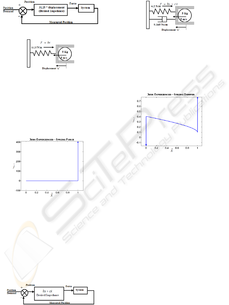
Figure 2: Impedance controller as spring.
Figure 3: Free Body Diagram: Spring system.
The jerk profile when using a spring to
decelerate the object is shown in Figure 4. It can be
seen that the jerk is zero initially when a spring is
used as compared to when applying a constant force.
However, at the end, when the body comes to rest,
the spring continues to apply a force proportional to
the displacement, and stopping the body at that
position results in a jerk spike as indicated.
Figure 4: Jerk when spring behaviour impedance is used.
3.3 Jerk Analysis – Spring Damper
In order to eliminate the jerk that occurs towards the
end of a spring system, the use of a critically
damped spring damper system is considered. The
impedance controller for this system is shown in
Figure 5. The desired impedance for this system is
given by
xckxForce
+=
, where ‘k’ is the spring
constant, ‘c’ is the damping constant, ‘x’ is the
displacement and ‘
x
’ is the velocity of the object.
The spring constant and damping constant are
chosen so that the body decelerates over 2m.
Figure 5: Spring Damper impedance control.
Figure 6: Free Body Diagram: Spring Damper System.
The values of ‘c’ and ‘k’ to achieve this are
found to be 9.165 Ns/m and 4.2 N/m respectively.
The resulting system would then behave as a spring
and a damper, the free body diagram of which is
shown in Figure 6. The force exerted to stop the
object is high initially and gradually decreases when
a spring damper is used.
Figure 7: Jerk when spring damper impedance is used.
Because the force is less towards the end, the
jerk towards the end is lower (for the chosen
sampling interval) than in the case of the spring.
However, the large amount of force applied at the
beginning results in a high jerk as shown in Figure 7.
4 BELL SHAPED IMPEDANCE
CONTROL
From the above analysis of using constant force,
spring and a spring damper to decelerate a body, it is
immediately clear that jerk is an issue with all the
methods. In theory, all these methods cause an
infinite amount of jerk on the body, and for the
chosen sample interval, a finite but large amount of
jerk as shown in the graphs. This jerk can be
responsible for an unsuccessful catch as the object
may bounce off on impact, or sustain damage. In
order to keep the jerk to a minimum, we propose a
new method of impedance control, where the
relationship between force and position is in the
form of a bell curve. The method uses knowledge of
statistics and probability distributions to establish
the required relationship. The graph of the
probability density of a raised cosine distribution is
BELL SHAPED IMPEDANCE CONTROL TO MINIMIZE JERK WHILE CAPTURING DELICATE MOVING
OBJECTS
507
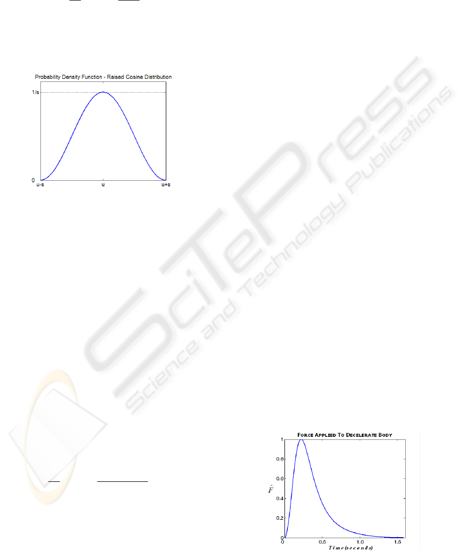
in the shape of a bell curve. This knowledge can be
used to establish a relationship between the force
and position. The probability density function of this
distribution is given as:
⎥
⎦
⎤
⎢
⎣
⎡
⎟
⎠
⎞
⎜
⎝
⎛
−
+=
π
s
ux
s
suxf cos1
2
1
),;(
(6)
and is supported in the interval u – s to u + s. The
amplitude of this distribution is 1/s and occurs at u
(Figure 8).
Figure 8: Raised Cosine Distribution - Bell Shaped.
It will be advantageous to establish a relationship
between force and position such that the body being
captured decelerates over a known distance and
experiences a certain maximum deceleration. From
the above equation (6), the distance over which the
object must decelerate is between u – s and u + s.
Hence, u and s are chosen as half the maximum
distance. Because the maximum amplitude is
dependant on s, a scaling factor is required to
achieve the required maximum deceleration for a
given distance. Hence, equation (6) is modified to
include a scaling factor A chosen such that A/s is the
maximum force tolerable. If the maximum
deceleration is known, the maximum force tolerable
by the object, using Newton’s equation is Force =
mass * deceleration. In order to establish an
impedance relationship, a force must be applied
depending on the position of the object and hence,
equation (6) can be written in terms of force and
position as
⎥
⎦
⎤
⎢
⎣
⎡
⎟
⎠
⎞
⎜
⎝
⎛
−
+=
π
s
uPosition
s
A
Force cos1
2
(7)
Equation (7) results in a force being output
depending on the position of the object and ensures
that the deceleration of the object is kept within the
tolerable limit. It is important to note that the area
under this bell curve determines the total work done,
and in order to decelerate the body to a complete
halt, this must be equal to the total kinetic energy of
the object. The area under this bell curve is 50% of
the total area under the rectangle with sides equal to
the maximum deceleration and maximum distance
over which the body decelerates. This is illustrated
in the example that follows. We compare this
method to the example used with the spring-damper,
spring and constant force methods. The distance
over which the body decelerates is 2m. Hence, u and
s are chosen to be 1 and the relative position of the
object is from 0m to 2m during which the force is
applied to decelerate the object. The maximum
amplitude of this curve is however 1/s which is
equal to 1, for the chosen s. The area under the
curve must be equal to the kinetic energy of the
object. For the 5kg mass travelling at 5m/s, the
kinetic energy is 62.5kgm
2
/s
2
(or Nm), as established
previously. The area under the bell curve is given as
Area = ½ * Force * displacement where Force is
worked out using Newton’s equation and
displacement is the distance over which the body
decelerates (50% area as mentioned earlier).
Equating this to the kinetic energy of the object, the
force required is found to be 62.5N. Hence, A must
be chosen such that A/s = 62.5. Since s = 1, A = 62.5.
Using the calculated values of A, u and s, the final
equation for force, in terms of position or the desired
impedance to minimize jerk is implemented.
The force applied to decelerate the object was
determined by the impedance relationship
established in equation (7). The maximum
deceleration experienced by the object is the same as
when a spring is used. A graph of force applied
using the impedance relationship to decelerate the
object against time is shown in Figure 9. Because
the position of the object changes faster initially due
to its approach velocity, the force required rises
steeply at the beginning. The force applied based on
the object’s position, slows the object down and
gradually eases off so as to stop the object over the
desired distance of 2m. The jerk profile for this
method is shown in Figure 10.
Figure 9: Force applied using Bell Shaped Impedance.
ICINCO 2007 - International Conference on Informatics in Control, Automation and Robotics
508
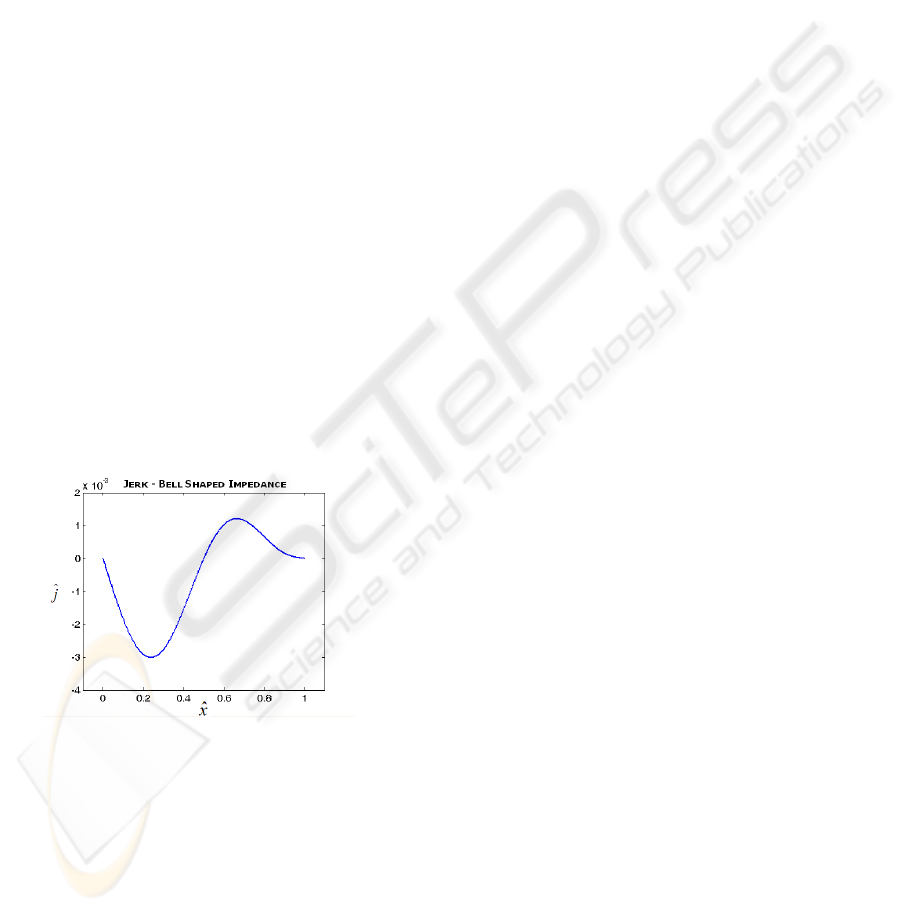
It is a smooth curve, with no spikes and the
amount of maximum jerk is very low as compared to
any of the other methods. In reality, actuators
themselves have inherent dynamics that prevent
them from generating instantaneous changes in
force. The greater the required instantaneous change
in force, the more pronounced the actuator dynamics
will become. Therefore, minimum jerk profiles, that
limit the required rate of change of force, can be
implemented with a greater degree of accuracy.
5 DISCUSSIONS & CONCLUSION
The jerk graphs reveal that the amount of jerk is
greatly reduced if a bell shaped curve of force
against position is used to capture the object (Figure
10). However, in comparison with the constant force
method, the amount of deceleration experienced by
the object is high. A trade off between the amount of
tolerable jerk and tolerable acceleration is required
to be able to generate the required response. An
important assumption in this method is that the
velocity and mass of the object at the point when
capture occurs is known. This ensures that the body
decelerates within a certain maximum distance and
allows for the force to be specified at every position
along its path. Any error in this estimation can result
in incorrect calculation of kinetic energy and the
object will not stop within the required distance.
Figure 10: Jerk for Bell Shaped Impedance control.
For accurate calculation, the velocity and mass of
the object must be estimated in real time, after which
self tuning can be used to generate the required bell
shaped impedance control. Additionally, capturing
an object requires a high speed of operation and it is
much more difficult to apply quick changing forces
from actuators at high speeds. The smooth bell
shaped acceleration profile also means that forces
can be applied with much more ease, due to the
gradually changing curve.
REFERENCES
P. Huang, Y. Xu, B. Liang (2006) Global Minimum-jerk
trajectory planning of Space Manipulator,
International Journal of Control, Automation, and
Systems, Vol. 4 (4), pp. 405-413.
K. J. Kyriakopoulos, G. N. Saridis (1991) Minimum jerk
trajectory planning for robotic manipulators, Proc.
SPIE, Vol. 1387, pp. 159-164.
A. Piazzi, A. Visioli (1997) An interval algorithm for
minimum-jerk trajectory planning of robot
manipulators, Proc. of the 36th Conference on
Decision and Control, San Diego, California USA, pp.
1924.
M. Muenchhof, T. Singh (2002) Desensitized Jerk
Limited-Time Optimal Control of Multi-Input
Systems, Journal of Guidance, Control, and
Dynamics. Vol. 25(3) pp.474-481.
K. J. Kyriakopoulos, G. N. Saridis (1988) Minimum-jerk
path generation, Proc. of IEEE International
Conference on Robotics and Automation, Philadelphia,
PA, pp. 364-369.
N. Hogan (1985) Impedance control: An approach to
manipulation: Part I- theory. Journal of Dynamic
Systems Measurement and Control, Vol.107(11), pp.1-
7.
P. J. Barre, R. Bearee, P. Borne, E. Dumetz (2005)
Influence of a jerk controlled movement law on the
vibratory behaviour of high-dynamics systems.
Journal of Intelligent and Robotic Systems. Vol. 42,
pp. 275–293.
S. Macfarlane and E. A. Croft (2001) Design of Jerk
Bounded Trajectories for On-line Industrial Robot
Applications. IEEE International Conference on
Robotics and Automation, Seoul, S. Korea.
J. Kovecses, W. L. Cleghorn, R. G. Fenton (1999)
Dynamic modelling and analysis of a robot
manipulator intercepting and capturing a moving
object with the consideration of structural flexibility.
Multibody System Dynamics 3, pp. 137–162.
Z. Lin, V. Zeman , R. V. Patel (1989) On-line robot
trajectory planning for catching a moving object.
Proceedings of the IEEE International Conference on
Robotics and Automation, Scottsdale, AZ, pp. 1726–
1731.
T. Sakaguchi, Y. Masutani, F. Miyazaki (1991) A Study
On Juggling Task, IEEE/RSJ International Conference
on Intelligent Robots and Systems, IROS 91, pp. 1418–
1423.
M. Buehler, D.E. Koditschek, P.J. Kindlmann (1994)
Planning and control of robotic juggling and catching
tasks. International Journal of Robotics Research,
Vol. 13(2), pp. 101-108.
R. R. Burridge, A. A. Rizzi, D.E. Koditschek (1995)
Toward a Dynamical Pick and Place. IEEE/RSJ
International Conference on Intelligent Robots and
Systems, IROS 95, Vol.2, pp. 292–297.
BELL SHAPED IMPEDANCE CONTROL TO MINIMIZE JERK WHILE CAPTURING DELICATE MOVING
OBJECTS
509
