
DISTRIBUTED EMBEDDED SYSTEM FOR ULTRALIGHT
AIRPLANE MONITORING
J. Kotzian and V. Srovnal, Jr.
Department of Measurement and Control, FEECS, VSB – Technical University of Ostrava, 17. listopadu 15
708 33 Ostrava – Poruba, Czech Republic
Keywords: Embedded systems, graphic interface, industrial bus, industrial sensors, operating systems, control system
design.
Abstract: This paper presents distributed embedded monitoring system that is developed for small aircrafts, sports and
ultralights airplanes. System is made from modules connected by industrial bus CAN. This low cost system
is trying to solve bad situation with many ultralights without any digital measurement unit due to their
prices. The contribution shows basic architecture of the embedded monitoring system and presents some
parts of hardware and software implementation. The interface between aviator and airplane is established
using graphic user interface based on operating system uClinux.
1 INTRODUCTION
This paper is concentrated to avionic system
especially to small sporting or ultralight airplanes.
Here is basic information about small airplanes.
Figure 1: Ultralight airplane – illustrative photo.
Ultralight airplane is constructed for maximally 2
persons, with a stalling speed lower than 65km/h and
a maximum flight weight of 450 kg. (Figure 1) Its
price is much lower than professional airplanes but it
is possible to fly for thousand kilometres. There are
many standards describe ultralight league in many
countries all over the world. The specification
mentioned above is validated for Europe especially
Czech Republic.
This project is focus on developing an alternative
to high price products. The project has been
developed together with the private company
FALKON Electronics. We have developed the
system architecture, which supports a flexible
configuration. The configuration can grow from
small, which measures basic values, to a wide range
system. This is possible thanks to the module
architecture.)
System is distributed into the independent
modules that measure specific value on mechanical
parts of the airplane. System is a configurable
according type of airplane. The highest layer is
graphic user module that represents received data on
the LCD display. Sense of monitoring system is
offer customers same facilities as have pilots in the
professional aircrafts and make aviation more easier
using low cost embedded electronic system.
2 AIRCRAFT MONITORING
VA L U E S
There are two basic groups of values which can be
measured. The first group includes flying values
such as attitude and air speed, the second group is
engine values as RPM and oil temperature. There is
448
Kotzian J. and Srovnal V. (2007).
DISTRIBUTED EMBEDDED SYSTEM FOR ULTRALIGHT AIRPLANE MONITORING.
In Proceedings of the Fourth International Conference on Informatics in Control, Automation and Robotics, pages 448-451
DOI: 10.5220/0001642804480451
Copyright
c
SciTePress
also a third group for other values such as battery
voltage, etc.
Fly values are the following:
• Attitude
• Altitude
• Airspeed
• Vertical Speed
• Gravitation
• GPS position
• Start, Fly, Actual Time
Engine values are the following:
• RPM
• Percent Power
• Oil temperature
• Oil pressure
• Cylinders temperatures
• Cylinders exhaust temperatures
The values that are mentioned above are only
basic group for our purposes. Using embedded
distributing system architecture we are able to
extended whole system within other values.
3 MONITORING SYSTEM
ARCHITECTURE
The real-time embedded control system is designed
with a modular structure (Li and Yao 2003). This
structure supports a flexible configuration. In terms
of user requirements, the control system can be
configured in different sizes and options. (Kotzian
and Srovnal 2004) Several modules with different
options were designed. All modules are connected to
an industrial bus – so each module is the bus node.
Except the GPS module, this is connected directly to
the main control module.
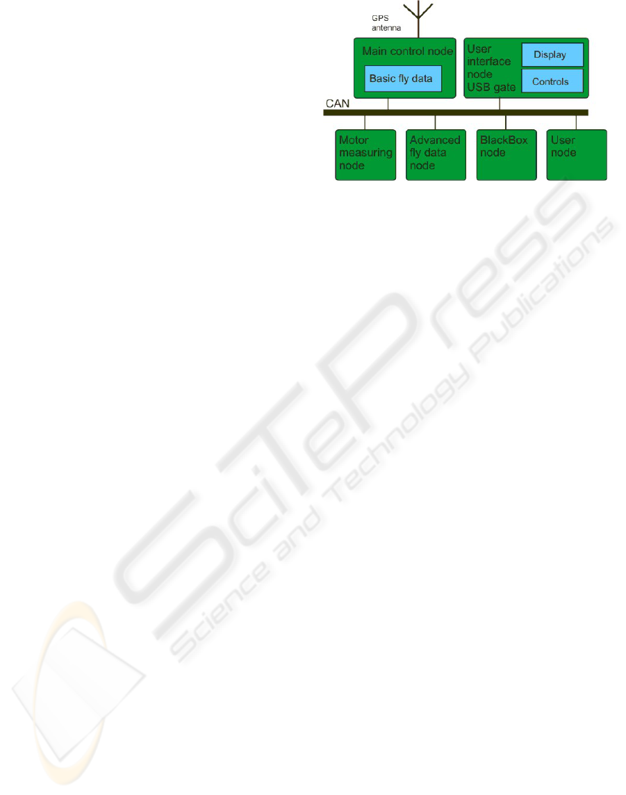
The block diagram of a desk control and
monitoring system with today’s full configuration of
prototype is shown in the Figure 2.
Designed modules are the following:
• Main control module
• User interface (LCD display) module
• Motor measuring values module
• Advanced avionic data module
• Black-Box module
Figure 2: Block diagram of monitoring system
4 SYSTEM MODULES
SPECIFICATION
The basic configuration contains only the User
Interface Module and the Main Control Module. The
Main Control Module has some basic inputs. Basic
values are connected to these inputs, which have to
be in the every airplane. The configuration can
measure attitude, altitude, airspeed, gravitation,
RPM, inside air temperature and battery voltage.
4.1 Communication Protocol
Monitoring modules are connected together by using
an industrial bus (Sridhar 2003). This bus has to be
highly reliable and have enough speed. Depending
on these two main requirements a CAN bus was
selected. The main reason is that the CAN has an
extremely low probability of non-detected error. The
versatility of the CAN system has proven itself
useful in other applications, including industrial
automation as well. A CAN bus is given the
international standard ISO11898 which uses the first
two layers of ISO/OSI model (CAN-CIA 2005).
(Kotzian and Srovnal 2003)
4.2 Main Control Module
The main control node serves as master for all other
nodes. (Arnold 2001) (Figure 3,4) Requesting values
from other nodes are compared with given limits and
stored in the local memory. The main module
decides what information will be display and send to
the user interface module by the CAN bus.
DISTRIBUTED EMBEDDED SYSTEM FOR ULTRALIGHT AIRPLANE MONITORING
449
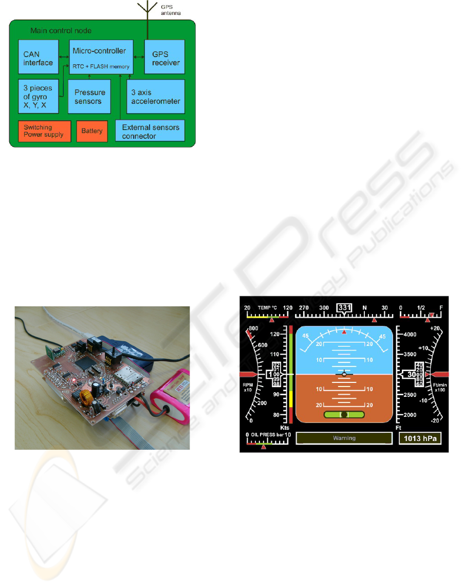
Figure 3: Main control node block diagram.
The main control module contains a real time
clock and data flash memory for storing measured
values and statistics. For measuring basic values the
main module is equipped with the following
measuring sensors:
• CSDX0811BARO for the altitude
• CSDX0025D4R for the air speed
• 3 x gyro sensor ADXRS401 for the attitude
• Accelerometer MMA7261Q
Figure 4: Main control module prototype (testing).
4.3 GPS Receiver
The GPS receiver is a small module with the passive
antenna for receiving the position information from
the global position system GPS. For its small size,
good features and low price GPS Orcam 21SB was
selected. The GPS module is integrated into the
Main Control Module. External antenna is used due
to the mounting possibility outside the plane (better
GPS signal). The GPS module is connected by using
a standard serial interface and standard GPS.
4.4 User Interface Module
The user graphic interface module serves as an
interface between the user and all monitoring
systems. There are two variants of the user interface
module, an economical and comfort version.
The economical version includes the
monochrome LCD Display GM62121 with the
320*248 pixels resolution. The economical version
is equipped with a 16bit DSP controller without any
operating system so it supports only necessary
functions.
The comfort version includes a color TFT
Display PD064 with a 640x480 pixels resolution.
This version is equipped with a 32-bit processor
(PPC or ColdFire) and operating system RT Linux
(support MMU) (Hollabaugh 2002) or uClinux
(MMU less). (
Raghavan, Lad, Neelakandan 2006) There
is also communication USB interface for storing the
measured data in to the user USB devices (Service
and diagnostic system). The operator panel of the
comfort version is shown in the figure 5. The
cheapest version uses a DSP controller as a display
content computation and FPGA as a display driver.
Figure 5: Main operator panel in cockpit.
It is possible to select the avionic screen, engine
screen or GPS map screen.
The firmware is based on embedded operating
system Linux using 240 MHz processor core. There
are implemented 4 interfaces in the operating
system. Two communication interface – CAN,
RS232 and USB and one display interface FB
(framebuffer) with the driver. Graphic system is
built on GUI – microwindows or miniGUI.
Those graphic user interfaces using two graphic
libraries SDL (Simple DirectMedia Layer) and
OpenGL ES. SDL is cross-platform multimedia
library designed to provide low level access to
ICINCO 2007 - International Conference on Informatics in Control, Automation and Robotics
450
audio, keyboard, mouse, joystick, 3D hardware via
OpenGL, and 2D video framebuffer. OpenGL ES is
a royalty-free, cross-platform API for full-function
2D and 3D graphics on embedded systems.
Software implementation is base on Eclipse
Workbench.
4.5 Black-Box Module
The black-box module controls all traffic on the
CAN bus. It reads data from CAN messages and
stores data in the local memory. The black-box
module is equipped with its own RTC timer and
stores time together with the CAN data. There is no
other connection to this module with such high
reliability.
5 DEVELOPING SYSTEM
CONFIGURATION
The project is presently in last of developing state.
We are beginning with the final versions of the
modules. The Main Control Module is designed in
its final version and is under testing.
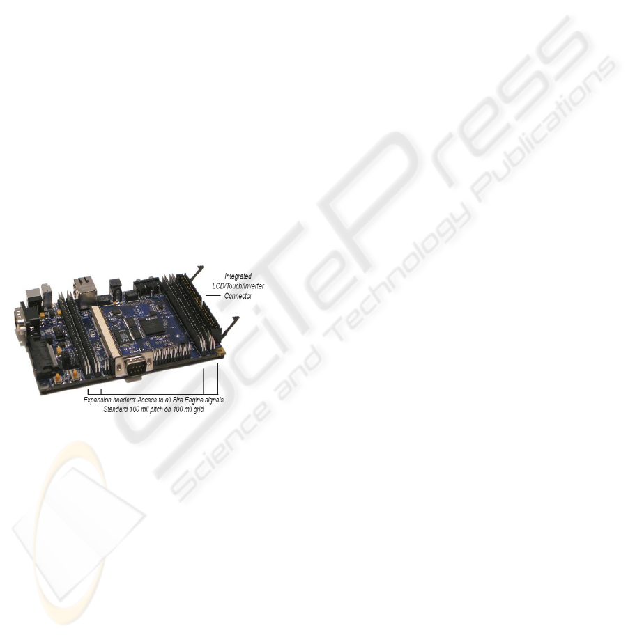
Figure 6: Evaluation kit for operator panel in cockpit.
Low cost version is based on EvbDSP module
with a DSP56F805 controller, six 8-bits ports, CAN,
SPI and serial interfaces and FPGA graphic driver
interface (User Interface Module). The EvbHCS12
module is equipped with a MC9S12DP256
controller (Main Control Module). This module
supports a wide range of interfaces: CAN, LIN,
serial, SPI, I2C and six 8-bit ports. The smallest
module is the EvbHCS08 with a MC9S08GT60
controller, LIN, SPI and serial interfaces,
temperature and humidity sensors and four 8-bit
ports (I/O devices). The comfort version has
different User Interface Module that is based on 32-
bit ColdFire controller (EvbMCF5329) with an
integrated display controller – GUI (Figure 6). For
EvbMCF5329 was used Linux BSP.(
Yaghmour 2003)
6 CONCLUSION
The development and realization of the avionic
control and monitoring system for ultra-light
airplanes is very important for increasing the safety
and security of pilots. The number of accidents of
ultra-light planes is too high, especially during the
starting and lending stages of flights. A low cost
flight control and monitoring system is the best way
to cut down on the number of accidents. The
developed monitoring system can be configured
from a minimal version to a wide system based on
customer requirements.
ACKNOWLEDGEMENTS
This project is being completed at VSB - Technical
University of Ostrava, Czech Republic. The work
and the contribution were supported by a project of
the Grant Agency of Czech Republic – 102/65/0571
Architectures of embedded system networks and
department of measurement and control.
REFERENCES
Arnold K. (2001) Embedded Controller Hardware Design.
LLH Technology Publishing USA 2001, ISBN 1-
878707-52-3
Sridhar T. (2003) Design Embedded Communications
Software. CMP Books, San Francisco 2003, ISBN 1-
57820-125-X
Raghavan P., Lad A., Neelakandan S. (2006) Embedded
Linux System Design and Development. Auerbach
Publication USA 2006, ISBN 0-8493-4058-6
Li Q., Yao C. (2003). Real-Time Concepts for Embedded
Systems, CMP Books, San Francisco 2003, ISBN 1-
57820-124-1
Hollabaugh, Craig., (2002). Embedded Linux, Pearson
Education, Indianapolis 2002, ISBN 0-672-32226-9
Yaghmour, Karim., (2003). Building embedded Linux
systems, O’Really & Assocites, Sebastopol 2003, ISBN
0-596-00222-X
Kotzian J. and Srovnal V. (2004). Development of
Embedded Control System for Mobile Objects Using
UML. In : Programmable Devices and Systems 2004-
IFAC Workshop, Krakow, IFAC WS 2004 0008 PL,
ISBN 83-908409-8-7, p.293-298
Kotzian J. and Srovnal V. (2003). Can Based Distributed
Control System Modelling Using UML. In:
Proceeding International Conference IEEE ICIT
2003, Maribor, Slovenia, ISBN 0-7803-7853-9,
p.1012-1017
DISTRIBUTED EMBEDDED SYSTEM FOR ULTRALIGHT AIRPLANE MONITORING
451
