
A SERVICE-ORIENTED FRAMEWORK FOR MANNED AND
UNMANNED SYSTEMS TO SUPPORT NETWORK-CENTRIC
OPERATIONS
Norbert Oswald, André Windisch, Stefan Förster
European Aeronautic Defence and Space Company - Military Air Systems
Herwig Moser
University of Stuttgart - IPVS
Toni Reichelt
Chemnitz University of Technology
Keywords:
Network-centric Operations, Autonomous Systems, Service-oriented Architecture.
Abstract:
Network-centricity and autonomy are two buzzwords that have found increasing attention since the beginning
of this decade in both, the military and civil domain. Although various conceptions exist of which capabilities
are required for a system to be considered network-centric or autonomous, there can hardly be found proposals
or prototypes that describe concrete transformations for both capabilities into software. The presented paper
reviews work accomplished at EADS Military Air Systems driven by the need to develop an infrastructure
that supports the realisation of both concepts in software with respect to traditional and modern software
engineering principles, e.g., re-use and service-oriented development. This infrastructure is provided in form
of a prototypical framework, accompanied by configuration and monitoring tools. Tests in a complex scenario
requiring network-centricity and autonomy have shown that a significant technical readiness level can be
reached by using the framework for mission software development.
1 INTRODUCTION
Network-centricity is a concept that becomes increas-
ingly interesting to both, the military and civil do-
main. It represents more than just connectivity across
systems and nodes, but between people in the infor-
mation and cognitive domains (NCOIC, 2005). Be it
military operations, international peacekeeping mis-
sions, large-scale commercial applications or natural
disasters, the complexity requires cooperating enti-
ties, collaborating to provide sufficient information,
resources and services to the collective. As some
mission are considered to be “dull, dirty and danger-
ous” (Freed et al., 2004), the use of unmanned au-
tonomous systems becomes an increasingly popular
alternative. Hence, manned and unmanned systems
need to be considered within Network-centric Opera-
tions (NCOs).
Prerequisite for a fast, efficient and effective col-
laboration in highly-dynamic missions is the creation
of a common understanding based on distributed situ-
ational information by means of an adequate IT in-
frastructure, comparable to the Global Information
Grid (GIG) (Alberts, 2003). Participating systems in
NCOs do not necessarily form a homogeneous collec-
tive but are usually composed of a patchwork of dis-
parate technologies, such as different communication
protocols, transport medias, software architectures,
processing platforms, or knowledge-based systems.
The consolidation of these technologies demands a
proper architectural concept for system interconnec-
tion and the availability of a corresponding frame-
work implementation. This problem is acknowledged
by the DoD Architecture Framework (DoD, 2003a)
but lacks an implementation.
The construction of such an architectural frame-
work is a very complex task due to its interdisci-
plinary nature. Although plenty of applicable soft-
ware standards (CORBA, FIPA, HLA, WSDL, . . . )
exist, composition is difficult because standards usu-
ally were designed independently of each other but in
this context have to work together. A further problem
284
Oswald N., Windisch A., Förster S., Moser H. and Reichelt T. (2007).
A SERVICE-ORIENTED FRAMEWORK FOR MANNED AND UNMANNED SYSTEMS TO SUPPORT NETWORK-CENTRIC OPERATIONS.
In Proceedings of the Fourth International Conference on Informatics in Control, Automation and Robotics, pages 284-291
DOI: 10.5220/0001649702840291
Copyright
c
SciTePress
arises from the fact, that it is partly unclear how tech-
nologies will evolve. Up to now, only few correlation
efforts have been made, e.g., JTA (DoD, 2003b) and
NC3TA (NATO, 2005), but those lack software engi-
neering aspects. Projects which do provide an imple-
mentation, e.g., OASIS (OASIS, 2006), COE (SEI,
1997) or JAUS (JAUS, 2006), concentrate on particu-
lar aspects but lack a holistic generic approach.
Thus, in this paper we combine NCOs and au-
tonomous systems approaches by presenting a frame-
work capable of constructing and assembling mission
software sufficing the needs especially of airborne,
but also ground-based or maritime participants, either
manned or unmanned in collaborative missions.
2 DISTRIBUTED AUTONOMY
REFERENCE FRAMEWORK
2.1 Design Principles
The conceptual development of a framework is driven
by the need to cover two fundamental principles, that
is, autonomy and NCOs. The combination of both
principles is modelled in the following using a mili-
tary analogy, but results can easily be mapped to the
civil domain. While NCO serves in both domains
to gain information superiority, autonomy in military
systems is usually associated with unmanned vehicles
but can also appear in command and control struc-
tures. A typical example is the so called Auftragstak-
tik (von Clausewitz, 1832). The core question is on
how to transform these basic principles thoroughly
into software.
Software Realisation
Military Doctrine
Auftrags−
taktik
Coop./Coord. &
Information Exchange
Common Operational
Picture
SOA
NCO
<<uses>>
<<uses>>
Agents
<<realises>>
Autonomy
<<realises>>
Services
Figure 1: Mapping of military doctrine to realisation in SW.
Figure 1 illustrates our view of the interplay of
military concepts transformed into the IT world, and
is split into an upper part, the Military Doctrine, and a
lower part, the Software Realisation. Auftragstaktik,
as shown on the upper-right side of the diagram, is a
military doctrine to give a sub-commander a goal to
achieve and leave a high degree of freedom concern-
ing actions for goal attainment (this equals “executive
autonomy” as defined in (Castelfranchi and Falcone,
2003)). In a dynamic environment, such as a bat-
tlefield, Auftragstaktik heightens efficiency through
adaptability to changing situations. The principle of
Auftragstaktik is also common in the civil domain as
exemplified by company hierarchies, where superiors
expect their subordinates to work independently but
goal-directed. Information exceeding a local view,
through the use of network-centric capabilities (i.e.,
«uses»), enables participants to better decide on how
to achieve their goals.
The lower part of the diagram shows the relevant
software concepts which we propose to implement the
doctrines. The desired autonomy is realised through
agent technology, which in turn, is based on and
makes use of a Service-oriented Architecture (SOA)
e.g.(W3C, 2004) (SCA, 2006). The use of SOA en-
ables units to become part of the NCO context, by
transparently providing and requesting services re-
spectively information to and from other vehicles.
The general approach is thus to provide an in-
frastructure which enables the creation of a service-
oriented architecture, supporting aspects to build sys-
tems exhibiting autonomous behaviour. The way how
services are internally structured and implemented
(e.g., in form of an agent) and where they are located
is transparent to the user.
2.2 Framework Features
We provide an infrastructure called Distributed Au-
tonomy Reference Framework (DARF) based on the
following core features:
Building Blocks: Providing service containers for
functionality to ease development of new services
or integration of existing code. The DARF in-
cludes a pre-fabricated building block, the Service
Broker which is described separately.
Situational Assessment: Providing means to build
an operational picture composed of shared dis-
tributed information, complement the world view
and to structure information using ontologies.
Decision Support: Providing means for the integra-
tion of reasoning and inference mechanisms, us-
age of declarative knowledge and to assist the de-
cision making process.
Network Communication: Providing a middleware
capable of communication in heterogeneous net-
working environments and platforms, adaptation
of transport media by IPv6 and service directory
service.
Simulation Connector: Integrate framework Build-
ing Blocks (see Section 2.3) into complex simula-
tion environments using High Level Architecture
(IEEE, 2000) standard technology.
This infrastructure forms the basis for the construc-
tion of services to be used in network-centric and au-
Figure 1: Mapping of military doctrine to realisation in SW.
Figure 1 illustrates our view of the interplay of
military concepts transformed into the IT world, and
is split into an upper part, the Military Doctrine, and a
lower part, the Software Realisation. Auftragstaktik,
as shown on the upper-right side of the diagram, is a
military doctrine to give a sub-commander a goal to
achieve and leave a high degree of freedom concern-
ing actions for goal attainment (this equals “executive
autonomy” as defined in (Castelfranchi and Falcone,
2003)). In a dynamic environment, such as a bat-
tlefield, Auftragstaktik heightens efficiency through
adaptability to changing situations. The principle of
Auftragstaktik is also common in the civil domain as
exemplified by company hierarchies, where superiors
expect their subordinates to work independently but
goal-directed. Information exceeding a local view,
through the use of network-centric capabilities (i.e.,
«uses»), enables participants to better decide on how
to achieve their goals.
The lower part of the diagram shows the relevant
software concepts which we propose to implement the
doctrines. The desired autonomy is realised through
agent technology, which in turn, is based on and
makes use of a Service-oriented Architecture (SOA)
e.g.(W3C, 2004) (SCA, 2006). The use of SOA en-
ables units to become part of the NCO context, by
transparently providing and requesting services re-
spectively information to and from other vehicles.
The general approach is thus to provide an in-
frastructure which enables the creation of a service-
oriented architecture, supporting aspects to build sys-
tems exhibiting autonomous behaviour. The way how
services are internally structured and implemented
(e.g., in form of an agent) and where they are located
is transparent to the user.
2.2 Framework Features
We provide an infrastructure called Distributed Au-
tonomy Reference Framework (DARF) based on the
following core features:
Building Blocks: Providing service containers for
functionality to ease development of new services
or integration of existing code. The DARF in-
cludes a pre-fabricated building block, the Service
Broker which is described separately.
Situational Assessment: Providing means to build
an operational picture composed of shared dis-
tributed information, complement the world view
and to structure information using ontologies.
Decision Support: Providing means for the integra-
tion of reasoning and inference mechanisms, us-
age of declarative knowledge and to assist the de-
cision making process.
Network Communication: Providing a middleware
capable of communication in heterogeneous net-
working environments and platforms, adaptation
of transport media by IPv6 and service directory
service.
Simulation Connector: Integrate framework Build-
ing Blocks (see Section 2.3) into complex simula-
A SERVICE-ORIENTED FRAMEWORK FOR MANNED AND UNMANNED SYSTEMS TO SUPPORT
NETWORK-CENTRIC OPERATIONS
285

tion environments using High Level Architecture
(IEEE, 2000) standard technology.
This infrastructure forms the basis for the construc-
tion of services to be used in network-centric and au-
tonomous scenarios. Furthermore, the framework of-
fers support for the systems engineering process via
system configuration, deployment and runtime exe-
cution monitoring.
2.3 Building Blocks
The DARF provides service containers which support
the construction of new services embedding mission
functionality. By turning mission functionality into
services, it becomes possible to distribute and use ser-
vices transparently of their location, and thus inde-
pendently of which platform
1
provides them.
The DARF provides containers for the implemen-
tation of intelligent and primitive services. This dis-
tinction is useful, as some services require decision-
making capabilities to fulfil their purpose. The “prim-
itive” qualifier does not imply that the logic behind a
service is trivial. It might encapsulate a highly com-
plex legacy functionality like, e.g., automatic target
recognition. Hence, primitive services, besides newly
developed functionality, may pose as a facade to a
legacy subsystem for which a standard way of integra-
tion has been developed as described in Section 2.3.4.
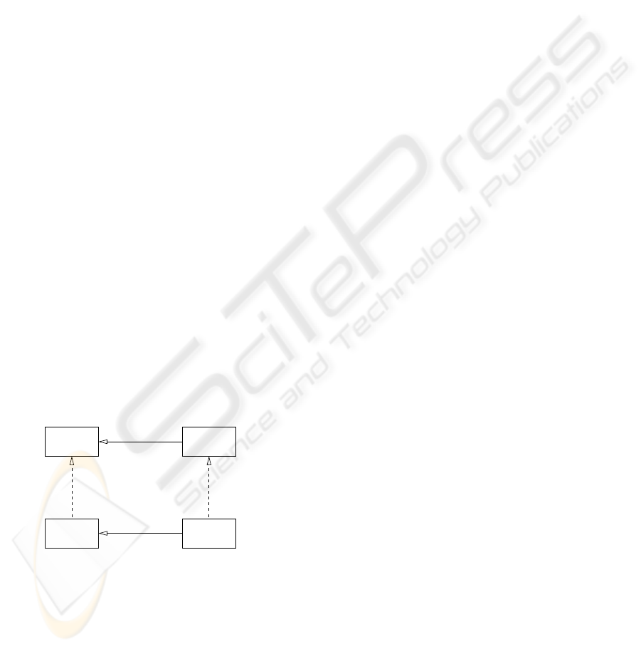
Figure 2 shows the meta-model of the building
blocks. The abbreviations introduced in the figure are
explained in the following sections.
tonomous scenarios. Furthermore, the framework of-
fers support for the systems engineering process via
system configuration, deployment and runtime exe-
cution monitoring.
2.3 Building Blocks
The DARF provides service containers which support
the construction of new services embedding mission
functionality. By turning mission functionality into
services, it becomes possible to distribute and use ser-
vices transparently of their location, and thus inde-
pendently of which platform
1
provides them.
The DARF provides containers for the implemen-
tation of intelligent and primitive services. This dis-
tinction is useful, as some services require decision-
making capabilities to fulfil their purpose. The “prim-
itive” qualifier does not imply that the logic behind a
service is trivial. It might encapsulate a highly com-
plex legacy functionality like, e.g., automatic target
recognition. Hence, primitive services, besides newly
developed functionality, may pose as a facade to a
legacy subsystem for which a standard way of integra-
tion has been developed as described in Section 2.3.4.
Figure 2 shows the meta-model of the building
blocks. The abbreviations introduced in the figure are
explained in the following sections.
<<is a>>
<<is a>><<realises>>
<<realises>>
APS
Service
AISCPS
CIS
Figure 2: Meta-model of the abstract respectively concrete
primitive and intelligent services.
2.3.1 Services
Both, primitive and intelligent services, have in
common that they advertise their service descrip-
tion/interface and may request services from others,
which first have to be discovered. This baseline func-
tionality is provided by the DARF and the Service
Broker, a distinctive service registry component, de-
scribed in Section 2.3.5. Services carry meta-data
1
In the military domain, the term “platform” is typically
correlated with a vehicle.
containing their interface description, configuration
and Quality-of-Service (QoS) parameters (see (Os-
wald, 2004)). The DARF uses this meta-data for ser-
vice start-up, registration and monitoring
At runtime, the DARF provides background man-
agement functionality which relieves service develop-
ers of writing tedious boilerplate code. That is, for
registration, the DARF automatically publishes the
service description and continues to asynchronously
check whether its publication is still valid. This is
necessary as the Service Broker may die and become
replaced, in which case the service gets re-registered
automatically.
The DARF provides client-side proxy classes (i.e.,
stubs) for every service. Upon the first invocation, re-
spectively after having lost connection to a service,
the proxy asks the Service Broker for a list of services
(“lazy resolution”) having a certain type and sufficing
a number of criteria prescribed by the client. The re-
turned list of services is then further sorted according
to a proprietary metric and results in the actual invo-
cation on the most appropriate service. This decision-
theoretic selection process is described in detail in
(Oswald, 2004).
2.3.2 Primitive Service
As mentioned before, services come in two flavours.
The first, and more basic one, being of the type Ab-
stract Primitive Service (APS). When adding func-
tionality and thus implementing a primitive service, it
becomes a Concrete Primitive Service (CPS). A CPS
is a leaf node component in a hierarchy of services,
representing a concrete atomic self-contained func-
tionality not explicitly requiring cognitive abilities. A
CPS may be a facade hiding a legacy subsystem.
2.3.3 Intelligent Service
The second type of service is the Abstract Intelli-
gent Service (AIS ), having two main characteristics.
First of all, they may make use of other services and
second of all, the decision on which services to use
respectively what actions to take is not hard-coded
but determined intelligently. Note that we agree with
(Clough, 2002) in that intelligence is not the same as
autonomy but will nevertheless equate intelligent ser-
vices with autonomous entities. Thus, similar to the
Auftragstaktik, intelligent services are given a goal
and are free (and capable) to choose how to attain
it. The DARF provides facilities for the implemen-
tation of rational agents. Related work in this field
can be found in (Karim and Heinze, 2005), employing
Boyd’s Observe Orient Decide Act (OODA) reason-
ing cycle, the accepted model of cognition of aircraft
Figure 2: Meta-model of the abstract respectively concrete
primitive and intelligent services.
2.3.1 Services
Both, primitive and intelligent services, have in
common that they advertise their service descrip-
tion/interface and may request services from others,
which first have to be discovered. This baseline func-
tionality is provided by the DARF and the Service
Broker, a distinctive service registry component, de-
scribed in Section 2.3.5. Services carry meta-data
1
In the military domain, the term “platform” is typically
correlated with a vehicle.
containing their interface description, configuration
and Quality-of-Service (QoS) parameters (see (Os-
wald, 2004)). The DARF uses this meta-data for ser-
vice start-up, registration and monitoring
At runtime, the DARF provides background man-
agement functionality which relieves service develop-
ers of writing tedious boilerplate code. That is, for
registration, the DARF automatically publishes the
service description and continues to asynchronously
check whether its publication is still valid. This is
necessary as the Service Broker may die and become
replaced, in which case the service gets re-registered
automatically.
The DARF provides client-side proxy classes (i.e.,
stubs) for every service. Upon the first invocation, re-
spectively after having lost connection to a service,
the proxy asks the Service Broker for a list of services
(“lazy resolution”) having a certain type and sufficing
a number of criteria prescribed by the client. The re-
turned list of services is then further sorted according
to a proprietary metric and results in the actual invo-
cation on the most appropriate service. This decision-
theoretic selection process is described in detail in
(Oswald, 2004).
2.3.2 Primitive Service
As mentioned before, services come in two flavours.
The first, and more basic one, being of the type Ab-
stract Primitive Service (APS). When adding func-
tionality and thus implementing a primitive service, it
becomes a Concrete Primitive Service (CPS). A CPS
is a leaf node component in a hierarchy of services,
representing a concrete atomic self-contained func-
tionality not explicitly requiring cognitive abilities. A
CPS may be a facade hiding a legacy subsystem.
2.3.3 Intelligent Service
The second type of service is the Abstract Intelli-
gent Service (AIS), having two main characteristics.
First of all, they may make use of other services and
second of all, the decision on which services to use
respectively what actions to take is not hard-coded
but determined intelligently. Note that we agree with
(Clough, 2002) in that intelligence is not the same as
autonomy but will nevertheless equate intelligent ser-
vices with autonomous entities. Thus, similar to the
Auftragstaktik, intelligent services are given a goal
and are free (and capable) to choose how to attain
it. The DARF provides facilities for the implemen-
tation of rational agents. Related work in this field
can be found in (Karim and Heinze, 2005), employing
Boyd’s Observe Orient Decide Act (OODA) reason-
ing cycle, the accepted model of cognition of aircraft
ICINCO 2007 - International Conference on Informatics in Control, Automation and Robotics
286
fighter pilots. The OODA loop is also the basis for the
operation of intelligent services and can be based on
a Belief Desire Intention (BDI) (Georgeff et al., 1999)
model as they are, in principle, quite similar.
Just as before, an Abstract Intelligent Service
(AIS) becomes a Concrete Intelligent Service (CIS)
when implemented.
2.3.4 Legacy Wrapper
Development of and for the DARF has to take into
account that there exists a large code base of proven-
to-work potentially certified code. It can not be as-
sumed that such code is in an easily accessible state.
That is, legacy code needs to be seen as something
almost entirely opaque. Still, a way of integrating
this functionality into the SOA needs to be provided
as not all functionality can simply be redeveloped to
fit the DARF interface. To tackle this problem, we
propose a standardised way of wrapping functional-
ity by using CORBA. Observe Figure 3, illustrating
on how this is done. Some legacy functionality f (x)
written in language l should be included. For that, it
is wrapped/adapted and made available by promoting
the wrapper’s interface as a CORBA server having an
OMG IDL interface. The choice of using CORBA
stems from the fact that there exist implementations
for almost any programming language and platform
available. Note that the Wrapper Server for f (x)
inherits its operations from the corresponding CPS.
This structural pattern is similar to the Wrapper Fa-
cade described in (Schmidt, 1999) and shares ele-
ments with the Adaptor pattern from (Gamma et al.,
1995). The Wrapper Server is managed by the Wrap-
per Manager. The manager is partly provided by
the DARF in form of an abstract super-class, capa-
ble of starting up the Wrapper Server and retrieving
its CORBA IOR (see (Siegel, 2000)) to instantiate a
client stub. The stub is used by the CPS to access the
legacy functionality via remote method invocation.
fighter pilots. The OODA loop is also the basis for the
operation of intelligent services and can be based on
a Belief Desire Intention (BDI) (Georgeff et al., 1999)
model as they are, in principle, quite similar.
Just as before, an Abstract Intelligent Service
(AIS) becomes a Concrete Intelligent Service (CIS )
when implemented.
2.3.4 Legacy Wrapper
Development of and for the DARF has to take into
account that there exists a large code base of proven-
to-work potentially certified code. It can not be as-
sumed that such code is in an easily accessible state.
That is, legacy code needs to be seen as something
almost entirely opaque. Still, a way of integrating
this functionality into the SOA needs to be provided
as not all functionality can simply be redeveloped to
fit the DARF interface. To tackle this problem, we
propose a standardised way of wrapping functional-
ity by using CORBA. Observe Figure 3, illustrating
on how this is done. Some legacy functionality f (x)
written in language l should be included. For that, it
is wrapped/adapted and made available by promoting
the wrapper’s interface as a CORBA server having an
OMG IDL interface. The choice of using CORBA
stems from the fact that there exist implementations
for almost any programming language and platform
available. Note that the Wrapper Server for f (x)
inherits its operations from the corresponding CPS.
This structural pattern is similar to the Wrapper Fa-
cade described in (Schmidt, 1999) and shares ele-
ments with the Adaptor pattern from (Gamma et al.,
1995). The Wrapper Server is managed by the Wrap-
per Manager. The manager is partly provided by
the DARF in form of an abstract super-class, capa-
ble of starting up the Wrapper Server and retrieving
its CORBA IOR (see (Siegel, 2000)) to instantiate a
client stub. The stub is used by the CPS to access the
legacy functionality via remote method invocation.
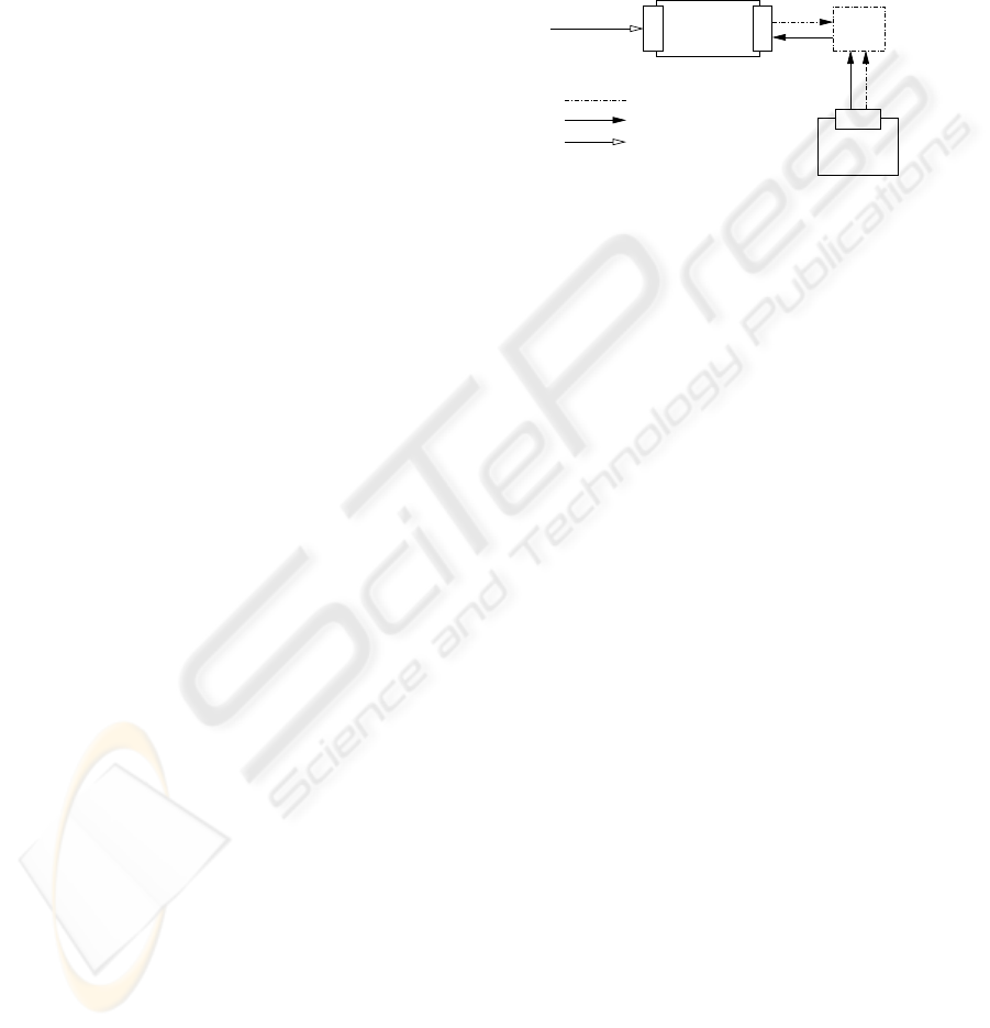
IDL
OMG
f(x)
lLang.
f(x)Legacy
lLang.
Wrapper Server
Manager
Wrapper
<<CPS>>
f(x)
g(f(x))
1..1
<<has a>>
<<RMI>>
<<manages>>
Figure 3: Wrapping legacy functionality f (x) in language l
using the DARF wrapper concept.
2.3.5 Service Broker
The Service Broker (SB) is a centralised service reg-
istry which itself is implemented as a service. It is
known to every service by providing its persistent ref-
erence in every service’s meta-data. The SB collects
service descriptions from services joining the system
and provides look-up facilities to service enquiries.
More than that, the SB constantly checks the consis-
tency of its references to services and discards broken
ones. Also, as each service may be replicated arbi-
trarily, it promotes service replicas to service masters
(i.e., the only active replica of a service) upon detec-
tion of a broken reference to the current master.
It should be noted that the SB is strictly limited to
service registration and discovery (it should thus not
be confused with the Broker pattern in (Buschmann
et al., 1996)).
2.4 Situational Assessment
A Blackboard as described in (Craig, 1995) is the en-
abling technology to achieve an operational picture
which forms the basis for any kind of potential ac-
tions and reactions of a single platform. The DARF
provides a distributed version of a Blackboard above
a DDS like system (OMG, 2005) to collect and ex-
change information. From the software architecture
point of view a Blackboard is a service used to share
information and knowledge between other services.
Both types of services might act on the one hand as
sources to provide processed data and inferred knowl-
edge to others by publishing it on the Blackboard. On
the other hand, services might subscribe for particular
information on the Blackboard.
As with service descriptions and naming, one has
to make sure during the engineering process, that all
represented information on the Blackboard will be
suitable for exchange between platforms. The use of
an agreed ontology guarantees, that a common lan-
guage is used. This is a key element in network-
centric operations as usually platforms of different
vendors with different systems are participating in
missions. The DARF intends to support embedding
and usage of various ontologies in the framework to
better structure the information, which requires na-
tional and international agreements, currently being
under investigation.
2.5 Decision Support
Decision making models like Boyd’s well known
OODA loop (Karim and Heinze, 2005) have been
widely used as the basis for developing Decision Sup-
port systems. They are tightly coupled with situa-
tional assessment and require, apart from their im-
plementation, a number of infrastructural measure-
ments. The DARF supports the embedding of Deci-
sion Support fundamentals with a number of features.
Firstly, DARF provides the internal structures of the
A SERVICE-ORIENTED FRAMEWORK FOR MANNED AND UNMANNED SYSTEMS TO SUPPORT
NETWORK-CENTRIC OPERATIONS
287
AIS building blocks to directly support the OODA
phases, including access to the distributed Blackboard
for information and knowledge exchange. Secondly,
DARF provides means to embed existing reasoning
and inference methods based on the legacy wrapper
concept. This includes handling of varying repre-
sentational structures, requiring adaptation to com-
ply with the one internally used for situational assess-
ment. Information and knowledge are explicitly ac-
cessible in a declarative manner. The declaratively
described rules can be changed interactively during
runtime execution, by the human system operator or
possibly by a CIS possessing learning algorithms.
The developed mechanism for Decision Support
assists the platform in a highly dynamic environment
by suggesting appropriate actions and while consider-
ing human interaction.
2.6 Network Communication
Network communication is based on IPv6 to hide
transport media specifics (Reichelt, 2006). IPv6
comes with a number of built-in capabilities which re-
lieve the DARF from having to take care of them. For
instance, IPv6 offers encryption, authentication and
auto-configuration of network nodes. Using IP(v6) al-
lows the use of various standard IP-enabled technolo-
gies. This allows for easy replacement or extension of
higher layer protocols or applications to increase the
flexibility of the DARF. Driven by the US Department
of Defense (DoD), essential technology standards for
NCOs and inter-system connectivity, i.e., the Global
Information Grid (GIG) (Alberts, 2003) and the Joint
Tactical Radio System (JTRS) (North et al., 2006), are
all based on IP(v6). The DARF seeks DoD compli-
ance in that respect.
The current prototypical implementation of the
DARF is written in Java and based on a CORBA
middleware (Siegel, 2000) for inter-service commu-
nication. The decision to base the communication
on CORBA originates from its wide support for het-
erogeneous distributed computing but binding to the
middleware is kept as loose as possible.
2.7 Simulation Connector
The frameworks capabilities for connecting possibly
distributed simulations is handled by an High Level
Architecture (HLA) connector. HLA is a middleware
standard supporting the development of distributed
simulations (IEEE, 2000). The HLA’s runtime im-
plicitly handles data transport across network connec-
tions as well as time synchronisation within a compo-
sition of separate simulations.
Within the DARF, HLA is used to validate sys-
tem functionality for different environments which
could not be provided by the experimental environ-
ment, e.g., the integration of a flight dynamic model.
Furthermore, a HLA model can be used to investigate
network or protocol behaviour by using communica-
tion simulators to emulate real world system intercon-
nection.
sion Support fundamentals with a number of features.
Firstly, DARF provides the internal structures of the
AIS building blocks to directly support the OODA
phases, including access to the distributed Blackboard
for information and knowledge exchange. Secondly,
DARF provides means to embed existing reasoning
and inference methods based on the legacy wrapper
concept. This includes handling of varying repre-
sentational structures, requiring adaptation to com-
ply with the one internally used for situational assess-
ment. Information and knowledge are explicitly ac-
cessible in a declarative manner. The declaratively
described rules can be changed interactively during
runtime execution, by the human system operator or
possibly by a CIS possessing learning algorithms.
The developed mechanism for Decision Support
assists the platform in a highly dynamic environment
by suggesting appropriate actions and while consider-
ing human interaction.
2.6 Network Communication
Network communication is based on IPv6 to hide
transport media specifics (Reichelt, 2006). IPv6
comes with a number of built-in capabilities which re-
lieve the DARF from having to take care of them. For
instance, IPv6 offers encryption, authentication and
auto-configuration of network nodes. Using IP(v6) al-
lows the use of various standard IP-enabled technolo-
gies. This allows for easy replacement or extension of
higher layer protocols or applications to increase the
flexibility of the DARF. Driven by the US Department
of Defense (DoD), essential technology standards for
NCOs and inter-system connectivity, i.e., the Global
Information Grid (GIG) (Alberts, 2003) and the Joint
Tactical Radio System (JTRS) (North et al., 2006), are
all based on IP(v6). The DARF seeks DoD compli-
ance in that respect.
The current prototypical implementation of the
DARF is written in Java and based on a CORBA
middleware (Siegel, 2000) for inter-service commu-
nication. The decision to base the communication
on CORBA originates from its wide support for het-
erogeneous distributed computing but binding to the
middleware is kept as loose as possible.
2.7 Simulation Connector
The frameworks capabilities for connecting possibly
distributed simulations is handled by an High Level
Architecture (HLA) connector. HLA is a middleware
standard supporting the development of distributed
simulations (IEEE, 2000). The HLA’s runtime im-
plicitly handles data transport across network connec-
tions as well as time synchronisation within a compo-
sition of separate simulations.
Within the DARF, HLA is used to validate sys-
tem functionality for different environments which
could not be provided by the experimental environ-
ment, e.g., the integration of a flight dynamic model.
Furthermore, a HLA model can be used to investigate
network or protocol behaviour by using communica-
tion simulators to emulate real world system intercon-
nection.
UAV
Model
<<CPS>>
GPS Sensor
Flight
Simulator
getGPS_Data()
subsribe()
reflect()
publish()update()
HLA Object Managment
HLA Data Flow
Service Invocation
Service
HLA
HLA
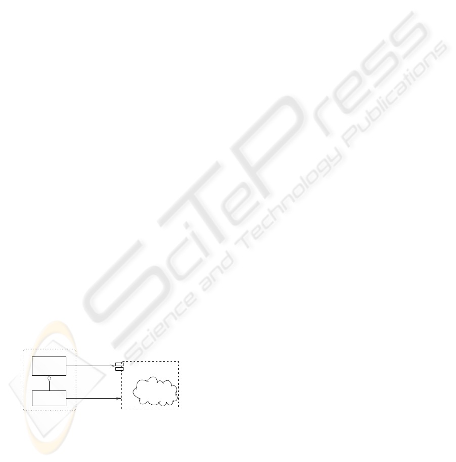
Figure 4: Integration of an HLA-enabled Flight Simulator
to provide GPS data via a service interface.
HLA interaction is realised through a CPS mak-
ing use of a simplified HLA API developed as part of
the DARF. Such a CPS provides two different inter-
faces: A service interface to the framework allowing
access to its data and an HLA interface to retrieve the
necessary information out of an HLA compatible sim-
ulation. Thus, the integration of simulators becomes
fully transparent by hiding the HLA interface behind
the framework’s SOA endpoint (see Fig. 4). This al-
lows easy replacement of the simulated data source by
a real-life one (and its appropriate CPS) without any
modifications of other system components.
3 SYSTEM LIFE CYCLE
SUPPORT
3.1 System Design Approach
Building industrial strength NCO-capable systems
with inherent autonomy requires besides the provi-
sion of an adequate runtime framework a well-defined
systems engineering process and an adequate tool
support for mission-specific system configuration, de-
ployment, and runtime-monitoring.
The system design approach used for DARF
Building Blocks follows the methodology defined by
the DoD Architectural Framework (DoDAF) (Alberts,
2003; DoD, 2003a). Initially the Concept of Op-
erations (CONOPS) is modelled which captures the
intended operational scenarios of the platform to be
built and deployed. This model also reveals the other
involved platforms, their operational roles, and the in-
formation flows between all of them. Based on this in-
ICINCO 2007 - International Conference on Informatics in Control, Automation and Robotics
288
formation, operational requirements for the platform
under consideration can be derived and the mission-
specific platform functions required for implementing
these requirements can be identified. The result of
this design step is a function graph, the systems view,
of the platform. It comprises a set of abstract DARF
Building Blocks linked by their service dependencies.
In case concrete implementations for the required ab-
stract Building Blocks already exist they can be used
immediately. Otherwise the corresponding concrete
Building Block software has to be designed, imple-
mented, tested, and integrated into the service pool.
3.1.1 System Configuration and Deployment
The System Configuration Tool (SCT) assists sys-
tem developers at design time in composing dis-
tributed systems from a given set of existing Building
Blocks and framework components. The application
of this tool at the system integration stage allows the
mission-specific configuration of platforms whilst en-
forcing both functional (e.g. functional completeness)
and non-functional (e.g. Worst Case Execution Times
or QoS aspects) system requirements as explained in
(Windisch et al., 2002).
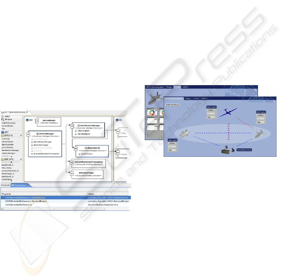
Figure 5: View of the System Configuration Tool.
The SCT, as depicted in Figure 5, is an Eclipse
based Integrated Development Environment that
comes with a graphical editor for composing dis-
tributed systems from a set of Building Blocks. All
available CIS and CPS Building Blocks are inferred
from the DARF upon tool start-up and displayed by
the graphical editor. System integrators can drag and
drop required Building Blocks to compose a system.
During this work the tool automatically resolves
all service dependencies of the currently used Build-
ing Block and graphically indicates any missing ser-
vices. Service meta-data can be changed by means
of the contained property table editor. Once ser-
vice composition is completed, i.e., a valid sys-
tem configuration in terms of fulfilled functional and
non-functional system requirements has been found,
the SCT tool generates all necessary DARF start-up
scripts and distributes them across the involved pro-
cessing nodes.
3.1.2 System Runtime Monitoring
The Mission Monitor tool offers views on both the
world scenario and the internal state of all involved
platforms. In a sense, the latter view constitutes the
runtime counterpart to the SCT tool, as it gains in-
sight into the mission-specific platform configuration
including all currently active services. The world sce-
nario view, on the contrary, depicts all involved plat-
forms from the system-of-systems level and provides
graphical information on their current state of inter-
connectivity in the highly-dynamic mission network
and currently active cooperations between platforms.
Figure 6: Mission Monitor.
The Mission Monitor is a web-server based ex-
tension of the DARF which continuously infers infor-
mation on service execution and interconnection from
the Service Broker components of the involved plat-
forms. This information is subsequently transformed
and published by a set of HTML pages which are dy-
namically created using Java Server Pages. One ad-
vantage of this approach is the fact that all informa-
tion is published in a network transparent manner and,
hence, can be obtained by any computing device run-
ning a standard web browser.
4 EXPERIMENTAL PLATFORM
To validate our approach, we have selected an in-
stance of a sensor-to-shooter scenario which is, in its
general case, well understood but still poses a chal-
lenge (Chapman, 1997).
A SERVICE-ORIENTED FRAMEWORK FOR MANNED AND UNMANNED SYSTEMS TO SUPPORT
NETWORK-CENTRIC OPERATIONS
289
4.1 Scenario
The basic idea is the cooperation between two kinds
of unmanned air vehicles, one acting as a reconnais-
sance unit (URAV
2
), essentially being the “sensor”,
and the other one acting as a combat unit (UCAV
3
),
representing the “shooter.”
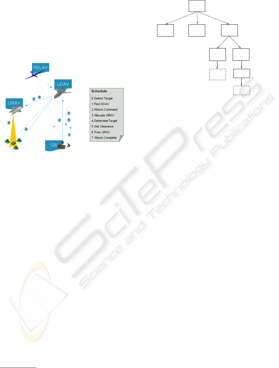
Figure 7: The sensor-to-shooter scenario.
Observe Figure 7, depicting the interaction of the
various platforms. Initially, only the URAV is in
the mission area, scanning it for potential threats.
Upon detection of a target (Step 0) by the URAV,
the Ground Station (GS)’s operator, who monitors
the URAV’s mission progress, locates an idle UCAV
(Step 1) and issues an attack command (Step 2). This
commands the UCAV to proceed to the mission area,
where it makes contact with the URAV (Step 3) to
acquire target information (Step 4). Having received
this information, the UCAV is ready to shoot but has
to wait for clearance from the GS operator (Step 5).
Once the clearance has been granted and the threat
was neutralised, the URAV may proceed with its re-
connaissance mission (Step 6). The UCAV’s mission
is complete once it informs the GS of the (success-
ful) outcome (Step 7). Each inter-platform commu-
nication within the scenario can potentially be routed
through a Relay to increase the communication range.
4.2 System Modelling and Execution
This section shows how DARF is used for system
development and mission execution for the scenario
described above. Also, it is demonstrated how the
DARF supports system validation through simulation.
2
Unmanned Reconnaissance Air Vehicle.
3
Unmanned Combat Air Vehicle.
general case, well understood but still poses a chal-
lenge (Chapman, 1997).
4.1 Scenario
The basic idea is the cooperation between two kinds
of unmanned air vehicles, one acting as a reconnais-
sance unit (URAV
2
), essentially being the “sensor”,
and the other one acting as a combat unit (UCAV
3
),
representing the “shooter.”
Figure 7: The sensor-to-shooter scenario.
Observe Figure 7, depicting the interaction of the
various platforms. Initially, only the URAV is in
the mission area, scanning it for potential threats.
Upon detection of a target (Step 0) by the URAV,
the Ground Station (GS)’s operator, who monitors
the URAV’s mission progress, locates an idle UCAV
(Step 1) and issues an attack command (Step 2). This
commands the UCAV to proceed to the mission area,
where it makes contact with the URAV (Step 3) to
acquire target information (Step 4). Having received
this information, the UCAV is ready to shoot but has
to wait for clearance from the GS operator (Step 5).
Once the clearance has been granted and the threat
was neutralised, the URAV may proceed with its re-
connaissance mission (Step 6). The UCAV’s mission
is complete once it informs the GS of the (success-
ful) outcome (Step 7). Each inter-platform commu-
nication within the scenario can potentially be routed
through a Relay to increase the communication range.
4.2 System Modelling and Execution
This section shows how DARF is used for system
development and mission execution for the scenario
2
Unmanned Reconnaissance Air Vehicle.
3
Unmanned Combat Air Vehicle.
<<uses>> <<uses>>
<<uses>>
<<connects>>
<<wraps>>
<<uses>> <<uses>><<uses>>
<<CIS>>
Identification
Manager
<<CPS>>
Identify
Objects
<<CIS>>
Eletro−
Optical
<<CPS>>
DVStreamer
<<Legacy>>
Image
Recognition
<<Device>>
Camera
<<CIS>>
Manager
Mission
Black−
Board
<<CPS>>
Determine
Target
<<CPS>>
Figure 8: Service Model of target determination.
described above. Also, it is demonstrated how the
DARF supports system validation through simulation.
According to the SOA principles, the desired plat-
form behaviour is broken down into corresponding
services. Services are either re-used from a custom
pool of existing mission functionality or has to be
newly developed by using the approach described in
Section 3.1. Figure 8 shows a concrete service de-
composition as part of the mission software. One of
the Mission Manager (MM)’s purposes is to acquire
and assess sensor information to determine possible
target candidates. For this, it makes use of the Iden-
tification Manager (IM) which delivers target classi-
fications. Based on the IM’s classification, the MM
uses the Determine Target service to select one target
out of a potential number of candidates. This target
is published on the Black Board (BB), promoting it to
system wide knowledge.
Services use the BB to implicitly distribute knowl-
edge which builds the operational picture of a single
platform. BBs can be synchronised between differ-
ent platform, propagating knowledge from one plat-
form to the other. This corresponds to Step 3 and 4
in our scenario, target information is transmitted from
the URAV to the UCAV. The actual target determi-
nation is performed by the DARF’s reasoning engine
using inference rules. Due to the declarative nature of
such rules, target prioritisation can be changed during
runtime.
As testing would be too risky and costly when per-
formed on real hardware (i.e., real UAVs), simulation
has to take its place. Flight controllers of the UAVs
interact with simulated flight dynamics models using
the DARF’s HLA connectivity. Using the same ap-
proach, other mission elements, such as radio links,
can be simulated to investigate system performance.
Figure 8: Service Model of target determination.
According to the SOA principles, the desired plat-
form behaviour is broken down into corresponding
services. Services are either re-used from a custom
pool of existing mission functionality or has to be
newly developed by using the approach described in
Section 3.1. Figure 8 shows a concrete service de-
composition as part of the mission software. One of
the Mission Manager (MM)’s purposes is to acquire
and assess sensor information to determine possible
target candidates. For this, it makes use of the Iden-
tification Manager (IM) which delivers target classi-
fications. Based on the IM’s classification, the MM
uses the Determine Target service to select one target
out of a potential number of candidates. This target
is published on the Black Board (BB), promoting it to
system wide knowledge.
Services use the BB to implicitly distribute knowl-
edge which builds the operational picture of a single
platform. BBs can be synchronised between differ-
ent platform, propagating knowledge from one plat-
form to the other. This corresponds to Step 3 and 4
in our scenario, target information is transmitted from
the URAV to the UCAV. The actual target determi-
nation is performed by the DARF’s reasoning engine
using inference rules. Due to the declarative nature of
such rules, target prioritisation can be changed during
runtime.
As testing would be too risky and costly when per-
formed on real hardware (i.e., real UAVs), simulation
has to take its place. Flight controllers of the UAVs
interact with simulated flight dynamics models using
the DARF’s HLA connectivity. Using the same ap-
proach, other mission elements, such as radio links,
can be simulated to investigate system performance.
ICINCO 2007 - International Conference on Informatics in Control, Automation and Robotics
290

5 CONCLUSIONS
Future mission software will have to possess network-
centric capabilities. Also, the advent of autonomous
systems changes the way missions are executed which
in turn influences the way software has to be de-
signed an developed. Complex operations relying
on the cooperation of manned and unmanned, pos-
sibly autonomous, entities require the possibility of
interaction by sharing tasks and exchanging informa-
tion and knowledge. We developed a framework, the
DARF, that uses a combination of SOA and agent
technologies to cope with the requirements of NCO-
enabledness and autonomy capabilities. That is, each
mission functionality is modelled as a service, ac-
cessible regardless of platform boundaries. Auton-
omy related functionality is supported by providing
infrastructural means for reasoning and knowledge
representation. Additionally, the standardised way of
legacy functionality integration allows easy reuse and
incremental adoption of the DARF.
To support developers, the DARF comes with a
defined engineering process and development as well
as maintenance tools. To investigate system perfor-
mance, the DARF offers a standardised and flexible
API to access distributed simulations.
We have validated our approach and shown the ap-
plicability of DARF using the well known sensor-to-
shooter scenario, exhibiting autonomous cooperative
behaviour. Future research on DARF will deal with
a unified middleware-independent messaging mecha-
nism, introduction of a general ontology and further
extension of the agent-related infrastructure.
REFERENCES
Alberts, D. S. (2003). Network centric warfare: curent sta-
tus and way ahead. Defence Science, 8(3).
Buschmann, F., Meunier, R., Rohnert, H., Sommerlad, P.,
and Stal, M. (1996). Pattern-Oriented Software Ar-
chitecture: A Systen of Patterns, volume 1. Wiley.
Castelfranchi, C. and Falcone, R. (2003). From automatic-
ity to autonomy: The frontier of artificial agents. In
Hexmoor, H., editor, Agent Autonomy, Multiagent
Systems, Artificial Societies, and Simulated Organi-
zations, chapter 6. Kluwer.
Chapman, W. G. (1997). Organizational concepts for
sensor-to-shooter world. Master’s thesis, School of
Advanced Airpower Studies, Alabama.
Clough, B. (2002). Metrics, Schmetrics! How The Heck Do
You Determine A UAV’s Autonomy Anyway? NIST
Special Publication, (990):313–319.
Craig, I. (1995). Blackboard Systems. Ablex Publ.Corp.
DoD (2003a). DoD Architecture Framework Version 1.0.
DoD Architecture Framework Group.
DoD (2003b). Joint technical architecture. http://www.
acq.osd.mil/osjtf/pdf/jta-vol-I.pdf.
Freed, M., Harris, R., and Shafto, M. G. (2004). Humans
vs. Autonomous Control of UAV Surveillance. In 1st
Intelligent Systems Tech. Conf., Chicago, USA.
Gamma, E., Helm, R., Johnsen, R., and Vlissides, J. (1995).
Design Patterns. Addison-Wesley.
Georgeff, M., Pell, B., Pollack, M., Tambe, M., and
Wooldridge, M. (1999). The belief-desire-intention
model of agency. In Müller, J., Singh, M. P., and Rao,
A. S., editors, ATAL ’98, volume 1555, pages 1–10.
Springer.
IEEE (2000). IEEE Std 1516-2000: IEEE Standard for
Modeling and Simulation High Level Architecture.
IEEE, New York, NY, USA.
JAUS (2006). Joint architecture for unmanned systems.
http://www.jauswg.org.
Karim, S. and Heinze, C. (2005). Experiences with the
design and implementation of an agent-based au-
tonomous uav controller. In AAMAS ’05, pages 19–26,
New York, NY, USA. ACM Press.
NATO (2005). C3 technical architecture. http://194.7.
80.153/website/home.asp.
NCOIC (2005). An introduction to the network centric op-
erations industry consortium (ncoic). Technical re-
port, NCOIC.
North, R., Browne, N., and Schiavone, L. (2006). Joint tac-
tical radio system - connecting the GIG to the tactical
edge. In MILCOM’06.
OASIS (2006). Reference model for service-oriented archi-
tectures. http://doc.oasis-open.org/soa-rm/
v1.0/soa-rm.pdf.
OMG (2005). Data distribution portal. http://portals.
omg.org/dds.
Oswald, N. (2004). Towards a Conceptual Framework-
Based Architecture for Unmanned Systems. In
ICINCO ’04, pages 118–126, Setúbal, Portugal.
Reichelt, T. (2006). Communication mapping for enter-
prise service architectures over heterogeneous trans-
port media. Master’s thesis, Chemnitz University.
SCA (2006). Service component architecture. http://
osoa.org/display/Main/Home.
Schmidt, D. C. (1999). Wrapper facade: A structural pattern
for encapsulating functions with classes. C++ Report.
SEI, C. (1997). Defense information infrastructure common
operating environment. http://www.sei.cmu.edu/
str/descriptions/diicoe_body.html.
Siegel, J. (2000). CORBA 3: Fundamentals and Program-
ming Second Edition. OMG Press.
von Clausewitz, C. (1832). Vom Kriege. Dümmlers Verlag.
W3C (2004). Web services architecture. Technical report.
Windisch, A., Fischer, M., and Förster, S. (2002). A re-use
orientated design methodology for future integrated
modular avionics systems. In FAST’02, pages 147–
153, London, UK.
A SERVICE-ORIENTED FRAMEWORK FOR MANNED AND UNMANNED SYSTEMS TO SUPPORT
NETWORK-CENTRIC OPERATIONS
291
