SKETCH INPUT OF 3D MODELS
Current Directions
Peter Varley and Pedro Company
Universitat Jaume I, Dept. of Mechanical Engineering and Construction, E-12071, Castellon, Spain
Keywords: Sketch Input, Solid Models, Computer-Aided Design, Natural Line Drawings, Wireframe Drawings.
Abstract: In the last few years, there has been considerable interest in sketch input of 3D solid models. This paper
summarises recent developments and discusses the directions these developments are taking. We consider
three developments in particular: the move away from line labelling as a technique in recognition of the
problem posed by extended vertices; the increasing use of symmetry detection as a tool for reconstruction;
and progress towards interpretation of drawings depicting curved objects.
1 INTRODUCTION
1.1 Objective
Our overall goal is to create a 3D solid model
automatically from a single 2D drawing. A tool
which could quickly interpret line drawings of
engineering objects as boundary representation CAD
models would be of significant benefit in the process
of engineering design. It would enable designers to
spend more time on the creative aspects of their job
and less on the routine aspects, it would reduce time
spent correcting mistakes by allowing instant
visualisation, and the simpler “what you draw is
what you imagine” interface will be less distracting
than an array of menus and icons.
1.2 Terminology
A drawing depicts an object. The junctions, lines
and regions of the drawing often, but not always,
correspond to the vertices, edges and faces of the
object.
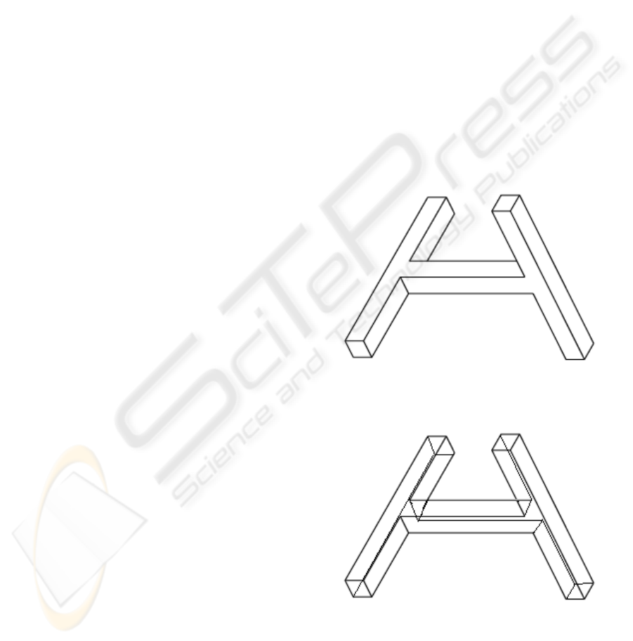
A drawing is a natural line drawing if it depicts
only those parts of the object visible from some
chosen viewpoint. It is a wireframe drawing if it
depicts all vertices and edges of the object.
A vertex is trihedral if exactly three edges meet
at it. An object is trihedral if all of its vertices are
trihedral.
Figure 1: Natural Line Drawing.
Figure 2: Wireframe Drawing.
85
Varley P. and Company P. (2007).
SKETCH INPUT OF 3D MODELS - Current Directions.
In Proceedings of the Second International Conference on Computer Vision Theory and Applications, pages 85-91
DOI: 10.5220/0002067200850091
Copyright
c
SciTePress
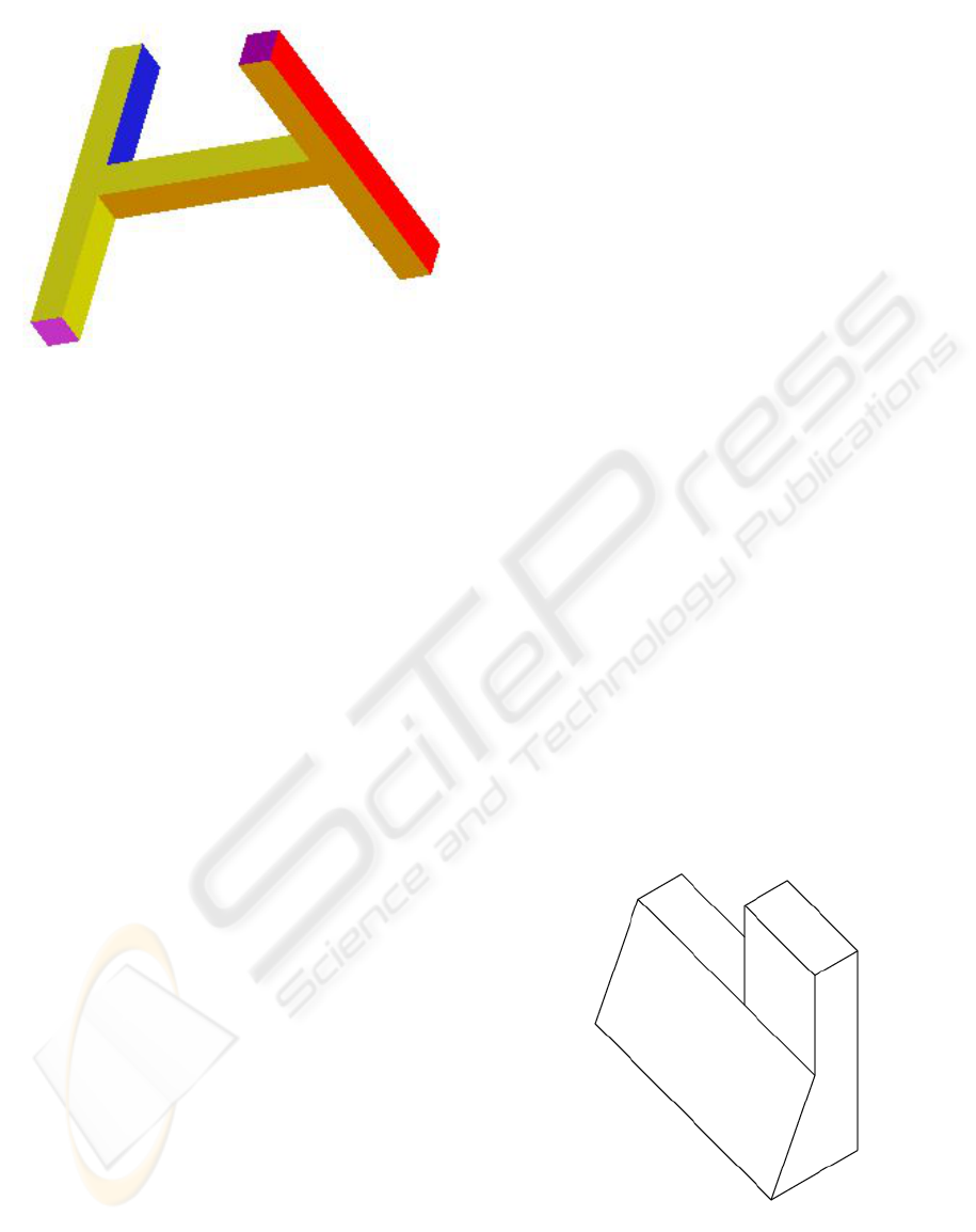
Figure 3: Object.
In engineering, our main interest is in solid
objects, the faces of which bound a single
continuous finite volume. A solid object is a
polyhedron if all of its faces are planar. A
polyhedron is a normalon if all of its edges and face
normals are aligned with one of three mutually
orthogonal axes, or a quasi-normalon if all of its
vertices terminate at least one edge aligned with one
of the three mutually orthogonal axes.
An object or drawing is described by its topology
(discrete data such as vertex/edge connectivity) and
geometry (continuous data such as vertex
coordinates and edge lengths). A drawing is from a
general viewpoint if no small change in the
viewpoint changes the topology of the drawing. We
assume that all drawings are from general
viewpoints.
1.3 Structure of Paper
This paper describes recent progress in interpreting
both natural line drawings and wireframe drawings.
There are some problems unique to one or the other
(for example, the question of what is around the
back of the object is unique to natural line
drawings), but there are also many problems,
notably that of determining design intent, which are
common to both.
Section 2 describes our baseline, the state of the
art as presented at the 1
st
SBM Workshop in
(Company, Piquer and Contero, 2004) and (Varley,
Martin and Suzuki, 2004).
The remainder of the paper outlines the trends
since then, and discusses the direction in which
current trends are moving.
Section 3 describes extended vertices, which
constitute a problem for many existing systems
which use line labelling.
Section 4 describes symmetry, a powerful tool
for determining design intent.
Section 5 describes progress towards
interpretation of drawings depicting curved objects.
2 BASELINE
The two systems we take as our baseline are
(Company, Contero, Conesa and Piquer, 2004) for
interpreting wireframe drawings and (Varley, Martin
and Suzuki, 2004) for interpreting natural line
drawings. The conclusions are as follows.
Interpretation of drawings depicting extrusions is
straightforward, regardless of the complexity of the
extruded face.
Interpretation of wireframe drawings depicting
normalons and quasi-normalons is straightforward
and fast. Interpretation of natural line drawings
depicting normalons depends on the ability of the
reconstruction engine to determine what lies around
the back of the object. The fact that the object can be
deduced to be a normalon is often a useful clue to its
structure. The object depicted in Figures 1-3
inclusive is at the limit of what can be interpreted in
the domain of normalons.
Interpretation of wireframe drawings depicting
non-normalons is slower, since an iterative
optimisation process is used to inflate the drawing
into 3D. It is also less reliable, since there will
always be some doubt about the choice of clues used
to construct the object, such as which three sets of
parallel lines depict edges aligned with the three
orthogonal axes.
Figure 4: Natural Line Drawing.
VISAPP 2007 - International Conference on Computer Vision Theory and Applications
86
Interpretation of natural line drawings of non-
normalons has met with limited success. Sometimes
other clues can be deduced—for example, if all
junctions in the drawing are trihedral, it is
reasonable to suppose that the depicted object is
trihedral too, and this aids the task of the
reconstruction engine.
Figure 5: Wireframe Drawing.
However, if even one of the junctions in the
drawing is non-trihedral (even implicitly non-
trihedral, as in Figure 4), the reconstruction engine
has few clues to work with. The object depicted in
Figures 4-6 inclusive is at the limit of what can be
interpreted in the general-case domain of non-
trihedral non-normalons.
Figure 6: Object.
3 EXTENDED VERTICES
This section illustrates extended polyhedral vertices
in the domain of natural line drawings. These
present a problem for traditional line labelling, and
serve to explain why recent systems have used
alternative methods of analysing frontal (visible)
geometry.
Line labelling as a concept was introduced by
(Huffman, 1971) and was first implemented by
(Clowes, 1971). Each line in the drawing is labelled
as either convex, concave or occluding. By this
means, useful clues to the hidden part of the object
can be deduced.
Traditional line labelling algorithms treat line
labelling as a purely combinatorial constraint
satisfaction problem, with 1-node constraints (each
junction must have a valid labelling) and 2-node
constraints (each line must have the same label
throughout its length). The catalogue of valid
junction labels for the domain of trihedral polyhedra
were determined by (Huffman, 1971). Other
catalogues followed, including those for trihedral
curved objects (Malik, 1987) and tetrahedral
polyhedra (Varley and Martin, 2001).
The first problem with line labelling is
conceptual: it cannot be a good idea to ignore the
geometry of the drawing at such an early stage of
processing.
The second problem with line labelling is
practical. Although those known line labelling
algorithms which are guaranteed to terminate are in
principle O(e
n
), in the domain of trihedral polyhedra,
practical performance often approaches O(n) (Parodi
et al, 1998). The reason for this is that the junction
catalogue for trihedral polyhedra is sparse: there is
often only one valid labelling, and line labelling
algorithms find it quickly. However, other
catalogues are not sparse, drawings of non-trihedral
objects often have many valid labellings, and
practical performance for these approaches O(e
n
).
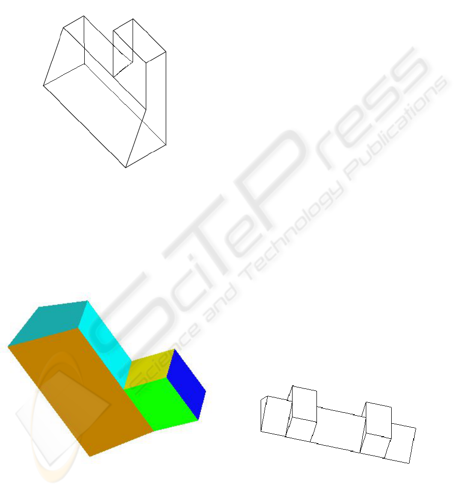
Figure 7: Problem Pentahedral Vertices.
Figures 7, 8 and 9, taken from (Varley 2005),
show drawings which catalogue-based labelling
cannot label. Even the pentahedral catalogue,
SKETCH INPUT OF 3D MODELS - Current Directions
87
required for Figure 7, is too large for practical
implementation, and there is the further problem in
this figure that a T-junction label which in the
trihedral domain always indicates an occluding T-
junction here corresponds to a genuine vertex.
The hexahedral and heptahedral junction
catalogues, are larger still—note that the junction of
six lines in Figure 8 implies the presence of a
seventh edge in the corresponding vertex of the
object, so the heptahedral catalogue would be
required. In addition, the hexahedral and higher-
order catalogues introduce the problem of two lines
which appear in the drawing to cross at a point
which is not the termination point of any line—an
example of this can also be seen in Figure 8.
Figure 8: Problem Higher-Valency Vertices.
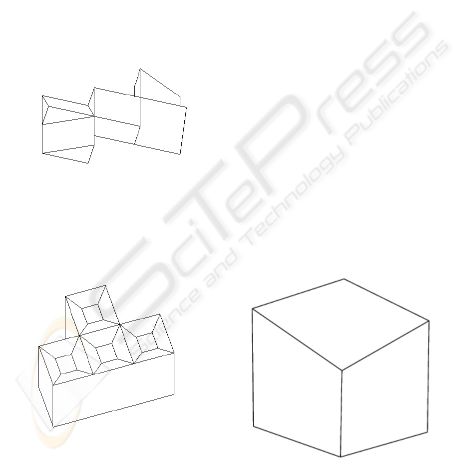
Figures 7 and 8 could, potentially, depict real
engineering objects. Figure 9 does depict a real
object, one which can be seen on many computer
keyboards. It is safe to say that the junction
catalogues required to label this object will not be
implemented in the foreseeable future.
Knowing that a problem exists is one thing;
finding the solution is another. However, the trend
seems to be clearly away from full line labelling. For
example, (Ku, Qin and Wright, 2006), who follow
tradition in most other respects, make no use of line
labelling.
One possibile alternative is to allow user
selection at some point in the process. For example,
(Kaplan and Cohen, 2006), who use Malik´s
catalogue for curved objects (Malik, 1987), found it
necessary to allow for manual intervention to guide
their labelling algorithm. However, this goes against
our desire for an approach which requires the user to
do nothing more than provide the initial sketch.
Another possibility, which we propose to
investigate, is whether partial line labelling
(labelling those edges which are in some way
obvious, while leaving unlabelled those edges which
are uncertain) provides enough useful clues for the
reconstruction engine.
Although line labelling as a tool has proved to be
a dead end, analysing why line labelling works in
the trihedral domain provides geometric insight
which remains useful in extended domains even
though the technique itself can no longer be
recommended.
4 DESIGN INTENT AND
SYMMETRY
This section discusses various uses of symmetry,
especially mirror symmetry, in determining design
intent.
The problem of determining design intent is
simple to state: what object did the user have in
mind when creating the drawing?
Figure 10: Misplaced Vertex?
Figure 9: Possible Engineering Object?
VISAPP 2007 - International Conference on Computer Vision Theory and Applications
88
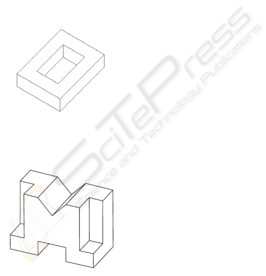
Figure 10 shows a simple example of the design
intent problem. Clearly, if the user intended to draw
a cube, the central vertex is misplaced. Was this, or
was this not, deliberate?
Figure 11 shows a more subtle example, and one
which could realistically occur in practice. The
height of the central feature is slightly less than the
height of the bounding box. Is this, or is this not,
deliberate? Depending on which interpretation we
choose, we get a different object. If we assume that
the difference was deliberate, the central feature is a
pocket, and the object is a tray. If we assume that the
difference was accidental, the central feature is a
through hole, and the object is a ring.
Figure 11: Tray or Ring?
If determining design intent is difficult even for
those parts of the object we can see, it is even more
difficult for those parts of the object we cannot see.
What, for example, is around the back of Figure 12?
Figure 12: What is the Back?
Since Marill´s pioneering work on inflation
(Marill, 1991), various clues, both geometrical and
perceptual, have been proposed in order to try to
capture different aspects of design intent. (Lipson
and Shpitalni, 1996) catalogued twelve regularities
which could be used for this purpose. However, the
problem of determining design intent remains
difficult to solve. Even apparently simple tasks such
as finding faces—the current state of the art, (Liu
and Lee, 2002), uses a genetic algorithm for this—
and finding the three main orthogonal axis—see
(Masry and Lipson, 2005) for wireframes and
(Varley, Martin and Suzuki, 2005) for natural line
drawings—are still challenging problems.
Nevertheless, by making assumptions about
engineering objects and the ways people see and
depict them, it is often possible to reproduce a single
object which humans will agree is the correct
interpretation of the drawing.
In trying to determine design intent, we believe
that we should assume certain regularities whenever
it is reasonable to do so. These regularities should be
those which are readily perceived, chiefly
perpendicularity and symmetry.
Geometrical techniques for identifying and
enforcing perpendicularity are well established.
(Martin, Varley and Suzuki, 2005) collects several
of these.
Enforcing symmetry is also straightforward, but
techniques for identifying candidate symmetries and
evaluating their merits are still work in progress.
Nevertheless, the power of symmetry as a tool is
evident. For example, once we have determined that
the object depicted in Figure 12 is mirror-symmetric
or the object depicted in figure 8 is axis-symmetric,
we are close to reconstructing them entirely.
At this stage, it is not even clear at what stage of
the process we should attempt to identify candidate
symmetries. Clearly, if we have a wireframe already
inflated to 3D, identifying candidate symmetries is
straightforward. But knowledge of the presence of
such a symmetry would be very useful in performing
the inflation. So which should be done first, inflation
or detection of symmetry? This is a question we
propose to investigate. (It should be noted that the
same question, the same arguments, and the same
uncertain conclusion, also apply to identifying faces
in wireframes.)
The answer is likely to depend on the quality of
algorithms available for detection of symmetry in
2D wireframes. This is not purely a graph
isomorphism problem—the geometry of the
wireframe must also be considered—so there is
considerable room for improvement in this area.
SKETCH INPUT OF 3D MODELS - Current Directions
89
Identification of candidate symmetries in 2D
natural line drawings is even more of a problem.
This is most difficult when different topology is
visible on the “near” and “far” sides of the mirror
plane, as in Figure 12, but even when the mirror
plane bisects the visible topology, finding it is not
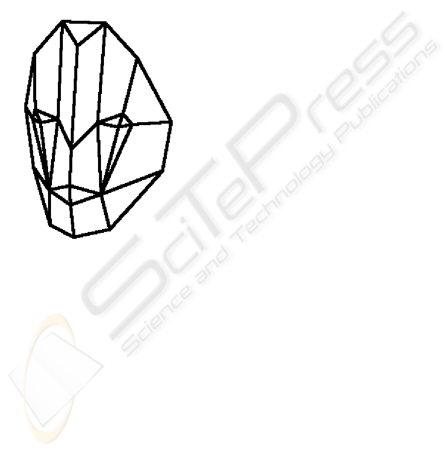
always straightforward. For example, we know of no
algorithm which detects only the “obvious” (to a
human) topological mirror symmetry in Figure 13
(and we should welcome a contribution from anyone
who does!).
Figure 13: Where is the Symmetry? (Takahashi, 2004)
5 CURVED OBJECTS
This section discusses various systems which allow
curved objects to be sketched.
In general, the more knowledge that can be built
in to the interpretation system, the better that system
will perform. For example, the method of
Constellation Models (Yang, Sharon and van de
Panne, 2005) (Sharon and van de Panne, 2006) is
generally successful in interpreting sketches of five
specific classes of object: face, flower, sailboat,
aeroplane or humanoid character. Each sketch is
assumed to be of an object of one of these classes. It
is allocated to the class which it matches best, and
analysed using domain-specific knowledge relating
to that class. Even with only five classes, the
occasional sketch is allocated to the wrong class, and
it seems inevitable that this misallocation will
increase as further classes are added. Additionally, it
is impossible to sketch any object not belonging to
one of these five classes.
The approach of (Takahashi, 2004) and (Varley,
Takahashi, Mitani and Suzuki, 2004), although
apparently more general, is in practice equally
limited. A sketch is interpreted by means of a
polyhedral template, either prepared in advance
(Takahashi, 2004) or created from, and topologically
equivalent to, the curved lines drawn by the user
(Varley, Takahashi, Mitani and Suzuki, 2004). In the
former case, the corresponding polyhedron is
specified when creating the template. In the latter
case, the corresponding polyhedron, which is
assumed to contain a plane of mirror symmetry, is
created using the methods described above (sections
2 and 4). In both cases, the 3D polyhedron is then re-
curved to match the user´s original drawing using
Loop subdivision (Loop, 1987). The assumption of
mirror symmetry is necessary in order to allow the
hidden part of the object to be curved. There are a
number of problems with this approach, not least
that, as seen in section 4, there is at present no
reliable algorithm for detecting 3D planes of mirror
symmetry in 2D natural line drawings.
The choice of Loop subdivision may not be
ideal—it is possible that other subdivision
algorithms would produce better results, and
alternatives such as the FIN algorithm (Gross, 2005)
are worth investigating. In considering such
algorithms, we must note a problem which must be
avoided: careless triangulation can lose the mirror
symmetry which we have gone to so much trouble to
identify.
The approach of (Kara and Shimada, 2006)
deforms a single polyhedral template in response to
curved strokes entered by the user. As with
(Takahashi, 2004), the template must be created
separately, but can be re-used for similar objects.
The assumption made in deforming the template is
physical rather than geometric: they imagine that the
faces of the template are thin membranes on which
pressure forces are exerted. Perhaps because of this
similarity to real-world objects, the results of this
process have an attractive appearance.
The approach of (Kaplan and Cohen, 2006)
creates a 2½D model. This demonstrates the limits
of what can be achieved without any assumptions or
templates. No attempt is (or can be) made to deduce
the hidden part of the object.
The quality of output achieved by the constraint-
based reconstruction used by (Kaplan and Cohen,
2006) is very high, but this comes at a price:
VISAPP 2007 - International Conference on Computer Vision Theory and Applications
90

rendering their final curved object takes minutes
rather than seconds or (ideally) fractions of seconds.
ACKNOWLEDGEMENTS
The support of the Japan Society for the Promotion
of Science (Fellowship no P03717) and the Ramon y
Cajal Scholarship Programme is acknowledged with
gratitude.
REFERENCES
Clowes, M., 1971. On Seeing Things. Artificial
Intelligence 2, 79–116.
Company, P., Contero, M., Conesa, J., Piquer, A., 2004.
An Optimization-Based Reconstruction Engine for 3D
Modelling by Sketching, Computers and Graphics
28(6), 955–979.
Company, P., Piquer, A., Contero, M., On the Evolution of
Geometrical Reconstruction as a Core Technology to
Sketch-Based Modelling, In ed. J. F. Hughes and J. A.
Jorge, Sketch-Based Interfaces and Modelling,
Eurographics Symposium Proceedings, 97–106.
Eurographics Press.
Gross, N, 2005. The FIN Algorithm-Using Subdivision
Methods for Computer Aided Design and
Manufacturing. Computer Graphics and Imaging, 49–
53.
Huffman, D., 1971. Impossible Objects as Nonsense
Sentences. Machine Intelligence 6, 295–323.
Kaplan, M, Cohen, E, 2006. Producing Models From
Drawings of Curved Surfaces, in ed. T. Stahovich and
M. Costa Sousa, Eurographics Workshop on Sketch-
Based Interfaces and Modelling, 51–58.
Kara, L.B., Shimada, T.,2006.Construction and
Modification of 3D Geometry Using a Sketch-Based
Interface, in ed. T. Stahovich and M. Costa Sousa,
Eurographics Workshop on Sketch-Based Interfaces
and Modelling, 59–66.
Ku, D.C., Qin, S.F., Wright, D.K., 2006. A Sketching
Interface for 3D Modelling of Polyhedrons, in ed. T.
Stahovich and M. Costa Sousa, Eurographics
Workshop on Sketch-Based Interfaces and Modelling,
83–90.
Lipson H. and Shpitalni M. 1996. Optimization-Based
Reconstruction of a 3D Object from a Single Freehand
Line Drawing. Computer-Aided Design. 28(8), 651–
663.
Liu J. and Lee Y.T. 2002. Identifying Faces in a 2D Line
Drawing Representing a Manifold Object, IEEE
Transactions on Pattern Analysis and Machine
Intelligence, 24(12), 1579–1593.
Loop, C.T., 1987. Smooth Subdivision Surfaces Based on
Triangles. Department of Mathematics, University of
Utah.
Malik, J., 1987. Interpreting Line Drawings of Curved
Objects. International Journal of Computer Vision,
73–103.
Marill, T. 1991. Emulating the Human Interpretation of
Line-Drawings as Three-Dimensional Objects.
International Journal of Computer Vision 6(2), 147–
161.
Martin, R.R., Varley, P., Suzuki, H, 2005.
Perpendicularity as a Key to Interpreting Line
Drawings of Engineering Objects, in Proc. Digital
Engineering Workshop: 5th Japan-Korea CAD/CAM
Workshop, 115–120.
Masry M., Lipson H. 2005. A Sketch-Based Interface for
Iterative Design and Analysis of 3D Objects. in
ed. J.
F. Hughes and J. A. Jorge, Sketch-Based Interfaces
and Modelling, Eurographics Symposium
Proceedings,109–118.
Parodi, P., Lancewicki, R., Vijh, A., Tsotsos, J. K., 1998.
Empirically-Derived Estimates of the Complexity of
Labeling Line Drawings of Polyhedral Scenes.
Artificial Intelligence 105, 47–75.
Sharon, D, van de Panne, M, 2006. Constellation Models
for Sketch Recognition, in ed. T. Stahovich and M.
Costa Sousa, Eurographics Workshop on Sketch-
Based Interfaces and Modelling, 19–26.
Takahashi, Y., 2004. Constructing 3D from Sketch
Portraits according to Prepared Templates, MSc
Thesis, The University of Tokyo. In Japanese.
Varley, P., 2005. Extended Vertices: A Problem for Line
Labelling, in Proc. Digital Engineering Workshop: 5th
Japan-Korea CAD/CAM Workshop, 106–114.
Varley, P.A.C., Martin, R.R., 2001. The Junction
Catalogue for Labelling Line Drawings of Polyhedra
with Tetrahedral Vertices, International Journal of
Shape Modelling 7(1), 23–44.
Varley, P.A.C., Martin, R.R., Suzuki, H, 2004. Can
Machines Interpret Line Drawings? In ed. J. F.
Hughes and J. A. Jorge, Sketch-Based Interfaces and
Modelling, Eurographics Symposium Proceedings,
107–116.
Varley, P.A.C., Martin, R.R., Suzuki, H, 2005. Frontal
Geometry from Sketches of Engineering Objects: Is
Line Labelling Necessary? Computer Aided Design 37
(12), 1285–1307.
Varley, P.A.C., Takahashi, Y., Mitani, J., Suzuki, H.,
2004. A Two-Stage Approach for Interpreting Line
Drawings of Curved Objects, in ed. J. F. Hughes and
J. A. Jorge, Sketch-Based Interfaces and Modelling,
Eurographics Symposium Proceedings, 117–126.
Yang, C., Sharon, D, van de Panne, M, 2005. Sketch-
Based Modelling of Parameterized Objects, in ed. T.
Igarashi and J.A. Jorge, Eurographics Workshop on
Sketch-Based Interfaces and Modelling, 63–72.
SKETCH INPUT OF 3D MODELS - Current Directions
91
