NON-PHOTOREALISTIC RENDERING OF ALGORITHMICALLY
GENERATED TREES
Nathan Dudley and Cindy Grimm
Boeing Co, Washington University in St. Louis, USA
Keywords:
Artistic rendering.
Abstract:
This paper presents a novel rendering technique inspired by artistic approaches. Instead of trying to recreate
a trad itional medium, such as charcoal or watercolor, this approach is a mixture of both photo-realism and
abstraction. Artists use a process of abstraction to provide structural information about subjects that do not
have clearly defined shapes, such as groups of leaves in a tree. For example, an artist will use a color wash to
first approximate a group of leaves. They then add detail on top of parts of this wash to indicate the presence
of individual leaves. Similarly, we use an abstract shape that approximates the image of leaves clustered at the
end of a branch. To prevent oversimplification, we add photo-realistic detail using a blending process. Inter-
frame coherence is achieved both by smoothly interpolating the abstract shapes, and the continuity inherent in
the photo-realistically rendered detail.
1 INTRODUCTION
This paper proposes a novel non-photorealistic
method to render algorithmically generated trees. In-
stead of trying to recreate the traditional medium that
an artist might use, such as watercolor or charcoal,
our approach is inspired by how artists use a combi-
nation of abstraction and detail to convey both shape
and texture in the scene. In particular, we look at how
artists render trees.
a)
b)
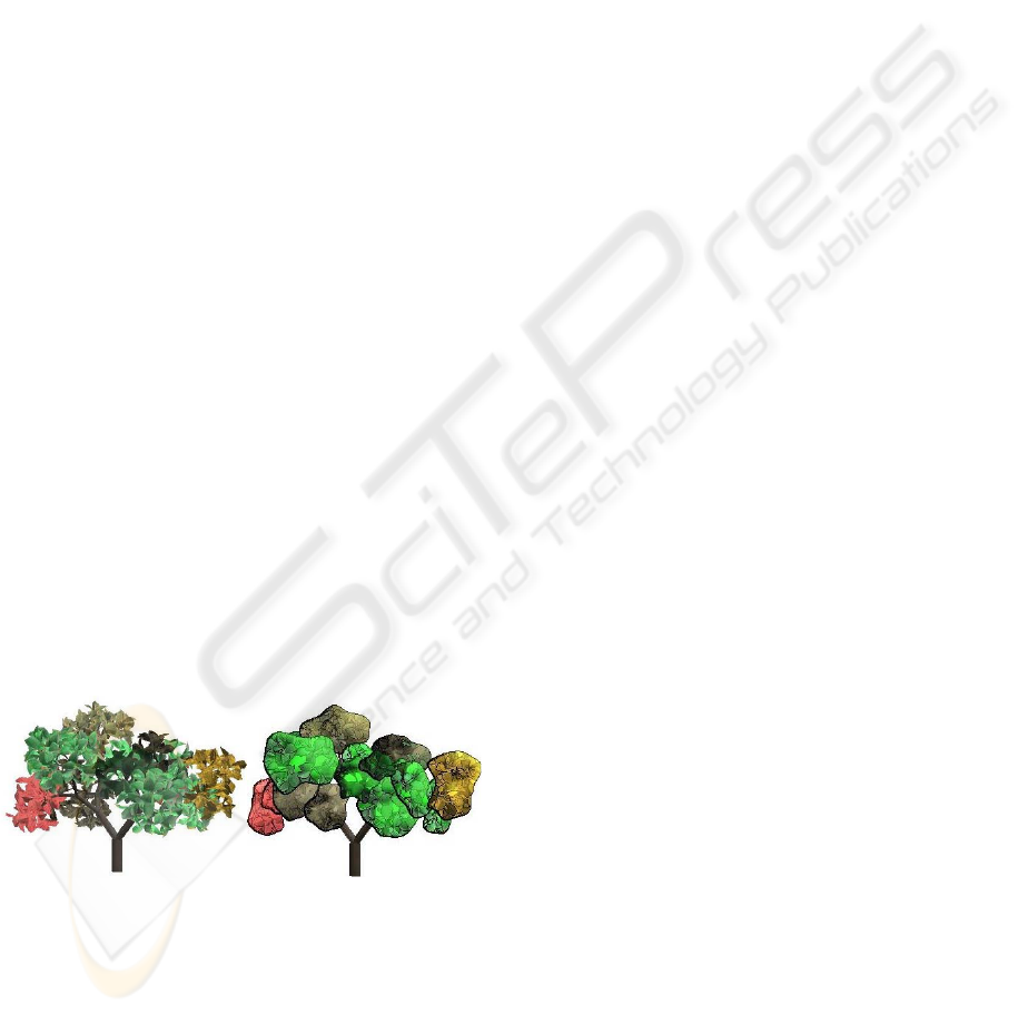
Figure 1: Goal of project. Left: a traditional photorealis-
tic rendering. Right: an alternative rendering that blends
abstraction with photorealism.
Long before computers created their first com-
puter generated images, humans developed many
methods, some realistic, some not, for depicting com-
plicated shapes such as trees. The first step in paint-
ing a tree with real paint is to consider the outline
shape of the tree (Lovett, 2004). Painting every leaf
would result in an overwhelming amount of detail. In-
stead, leaves should be viewed as a mass and painted
in clumps (Boddy-Evans, 2005). To give a sense of
texture, a couple of the leaves should be drawn accu-
rately (Bourdet, 2001). The goal of this paper is to
create images inspired by this approach.
Artists use abstraction to provide structural in-
formation about subjects that do not have obvious
shapes. For example, a wash of color represents a
group of leaves. To convey detail, artists then paint in
representative leaves, but only in places. Similarly,
large branches are depicted in detail while smaller
branches might be left out altogether.
We mimic this approach to render algorithmically
generated trees. Leaves at the end of branches are
clustered into one coherent unit which are then ren-
dered with substitute geometry that suggests the shape
of the original leaves. The resulting image has a
cartoon-like appearance which is then offset by intro-
ducing photo-realistic detail using a blending process.
We render only the larger branches, omitting smaller
ones in the leaf groups.
We provide several artistic options to alter the ap-
pearance of the final rendering. Outlining the blobs
provides visual structure to the image and enhances
perspective. The location, and strength, of detail is
important when painting. The rendering application
allows the user to control the amount of detail to use,
197
Dudley N. and Grimm C. (2007).
NON-PHOTOREALISTIC RENDERING OF ALGORITHMICALLY GENERATED TREES.
In Proceedings of the Second International Conference on Computer Graphics Theory and Applications - GM/R, pages 197-203
DOI: 10.5220/0002072201970203
Copyright
c
SciTePress
and where to apply it.
Ensuring inter-frame coherence is a challenge in
non-photorealistic approaches. Because we are us-
ing detail drawn from the photo-realistic rendering
process, this detail is visually stable from frame to
frame. To ensure that the abstract information is sta-
ble, we apply the full rending process every n frames,
then interpolate the abstract data for the intermediate
frames.
Contributions: We present a new, art-based ren-
dering technique that combines abstraction with pho-
torealism. This approach mirrors the artistic process
rather than the re-creating a traditional media. Al-
though in this paper we focus on algorithmically gen-
erated trees, the method could easily be extended to
arbitrary scenes.
Previous work is provided in section 2. A descrip-
tion of L-systems is provided in section 3. Section
4 describes how the groups of leaves are rendered.
Chapter 5 discusses maintaining inter-frame coher-
ence. Results are contained in section 6. Section 7
provides a conclusion and describes future work.
2 PREVIOUS WORK
There is a large (and growing) body of work in non-
photorealistic rendering. We focus on methods that
have been adapted specifically for rendering trees. In
the following section we discuss the plant generation
software (L-Systems) used to generate the models for
this paper.
In the past, computer graphics rendering fo-
cused primarily on producing photographic im-
ages (Markosian et al., 1997). Non-photorealistic
rendering, on the other hand, may focus on abstrac-
tion and simplification, such as the work by Kowal-
ski et al (Kowalski et al., 1999). In this ap-
proach the authors use strokes to render 3D com-
puter graphics scenes in a stylized manner to sug-
gest the complexity of the scene (by drawing a few
leaves at the silhouettes) without representing it ex-
plicitly. Other approaches mimic particular media,
such as stippling (Deussen et al., 2000), charcoal
rendering (Meier, 1996), engraving (Ostromoukhov,
1999), and half toning (Freudenberg et al., 2002).
Deussen (Deussen and Strothotte, 2000), Luft (Luft
and Deussen, 2006) and Fiore (Di Fiore et al., 2003)
focus on using stippling, water colors, and cartoon
rendering, respectively, for trees.
Alvy Smith was the first to use Lindenmayer
systems (L-systems) to render representations of
trees (Smith, 1984). The method in this paper also
uses L-systems to create the base 3D models from
which to draw. In particular, we use Prusinkiewicz’s
approach to modeling and visualization of plants us-
ing L-systems (Prusinkiewicz, 2004).
3 USING L-SYSTEMS TO
CREATE TREES
We use L-systems to create the 3D tree mesh data. We
post-process the mesh data to reduce the mesh com-
plexity, ensure that the meshes are closed, and to ex-
tract the branches and leaf groups.
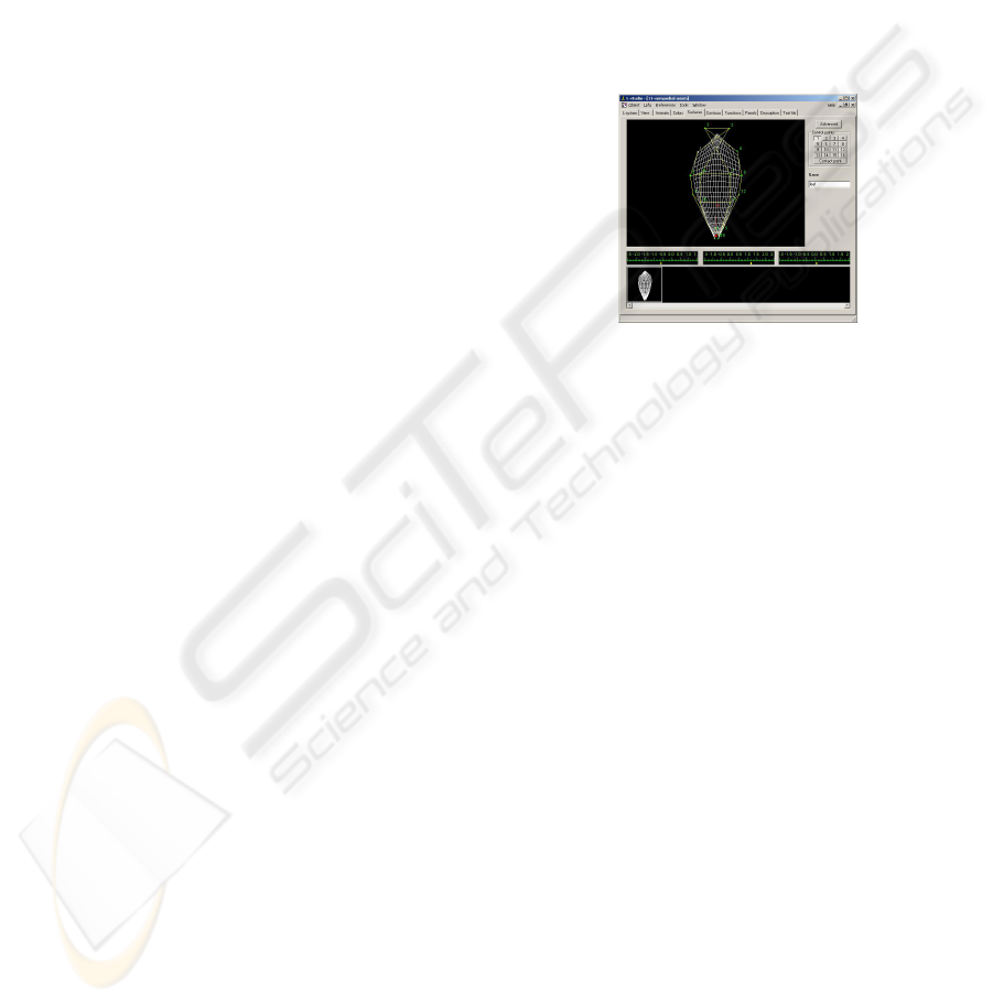
Figure 2: Creating a leaf mesh using L-studio.
3.1 Creating the Mesh
The advantage of using 3-D data (Deussen and
Strothotte, 2000) is that we can use automated tools
to generate the trees. A 3D model of the tree provides
the necessary information about the structure of the
tree. We used L-studio 4.0 (Karwowski and Lane,
2004) to generate the trees used in this paper.
In its basic form, a Lindenmayer system, or L-
system, consists of a starting string of symbols from
an alphabet, and a series of transitions specified by
a list of search-and-replace rules. During each re-
cursive step, zero or more rule-based transitions are
applied to the string. Each rule consists of an input
substring to be replaced and the string to replace it
with. The ordering of the rules is significant. (Fran-
cis, 2002) L-studio also provides several functions to
control the size of the leaves, and the length and size
of the branches based on growth time. The trees used
in this paper have a single leaf shape.
We need to group the leaves based on their level
in the hierarchy (essentially, all leaves produced after
level l are grouped). When L-studio creates the output
file, it lists the leaves and branches in the order that
they were generated. To determine the group to which
a leaf belongs we use a threshold value based on the
diameter of a branch. The program reads leaves until
the next time that the diameter of a branch crosses
GRAPP 2007 - International Conference on Computer Graphics Theory and Applications
198
the pre-defined threshold value. This triggers a new
group of leaves to be started. This process is repeated
until all of the leaves are read and placed into a unique
grouping.
Leaves and branches constitute the smallest con-
nected grouping in a mesh. We apply one texture to
the branches and a separate one to the leaves. The
meshes belonging to the branches below level l (i.e.,
the trunk and big branches) are separated out and la-
beled as a single group.
3.2 Modifying the Mesh Resolution
The resolution at which L-Studio creates the leaf and
branch meshes is higher than we need, so we simplify
them. Also, the leaf meshes are one sided, so we du-
plicate the leaf mesh, reverse the orientation, and add
thickness.
Textures
No leaf edge
silhouettes
Black leaf edge
silhouettes
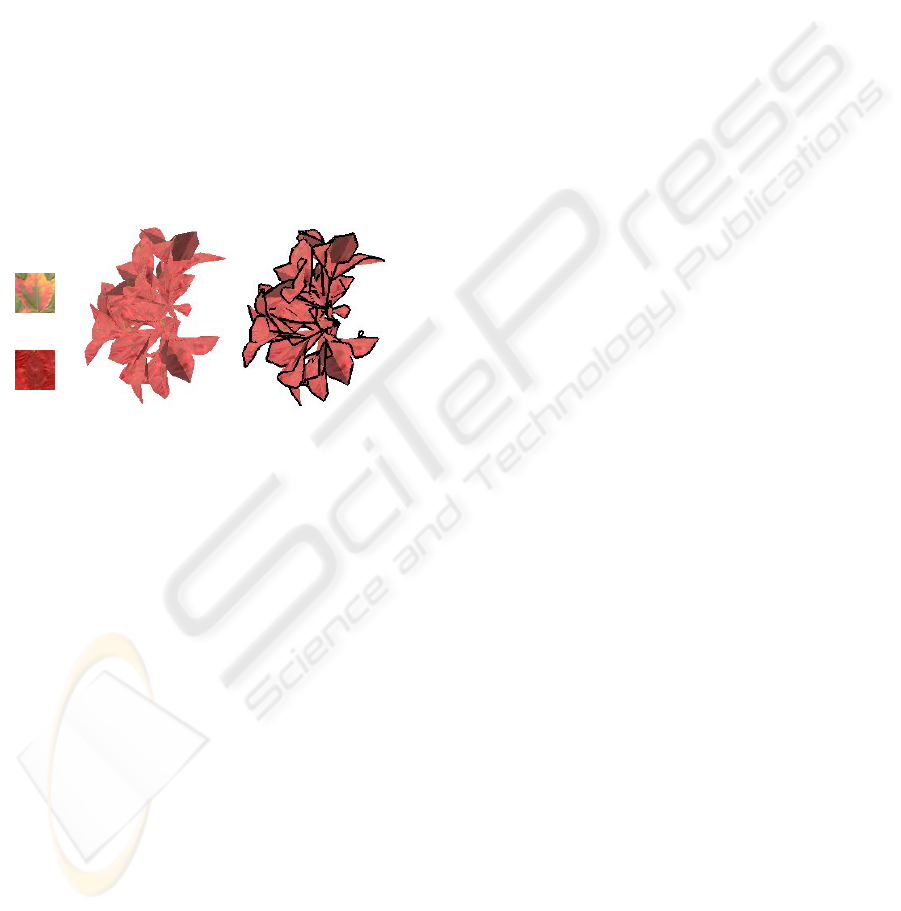
Figure 3: Options for drawing a group of leaves. (Left) Tex-
tures used (Center) Leaves drawn without edges hilighted.
(Right) Leaves drawn with edges hilighted. .
The leaf textures (see figure 3) are a mix of
photographs and hand-painted images. Options for
selecting where to apply texture include leaf only,
branch only, and recursively. The texture can either
be applied to every face or can be stretched out over
every face in a leaf.
The rendering application uses of an id buffer to
determine which pixels a leaf group (or branch) occu-
pies. We assign a unique id to every leaf group and
branch.
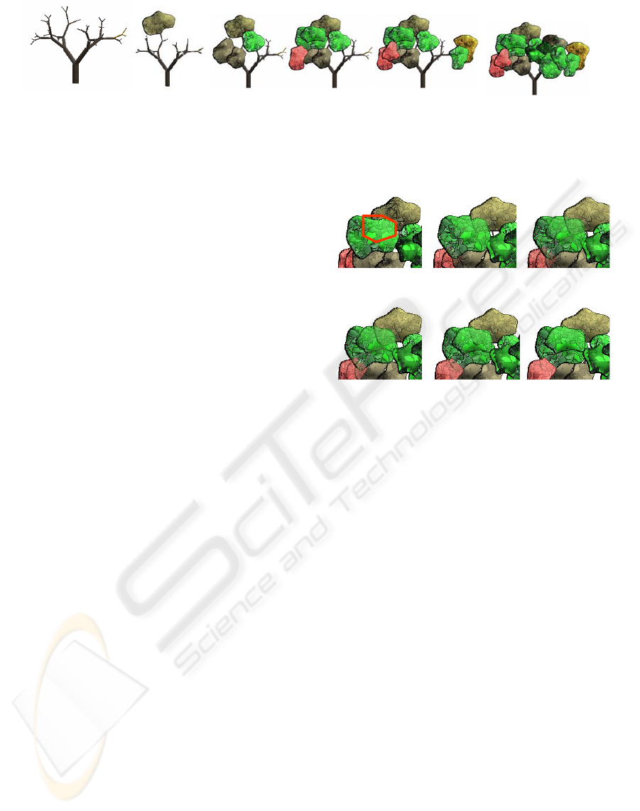
4 RENDERING
This section describes the rendering process for cre-
ating a single frame (see figure 4). The render-
ing process begins by clustering leaves into groups
(blobs). We create approximate, 3D, screen-aligned
geometry for each group (the blob geometry). This
geometry serves two purposes. First, we render the
blob geometry using approximate colors to produce
an abstract rendering of the group. Second, we use the
blob geometry to produce an alpha mask which tells
us where to add in detail. This alpha mask is used to
combine the abstract rendering with a photo-realistic
rendering of the leaves to create a billboard image for
the blob. (Note: By photo-realistic we mean tradi-
tional OpenGL, or ray tracing, Phong, etc., render-
ing.)
Once the billboard images are created, we add
depth and combine them, with the large branches and
trunk, into a single image.
4.1 Lighting
The user specifies two sets of lighting arrangements.
The first set of lights, the scene lights, is used to
light the tree in the traditional manner. The second
set of lighting (the blend lighting) is used to deter-
mine where to mix the photorealistic rendering with
the non-photorealistic rendering. This is described in
more detail in section 4.2.2.
4.2 Rendering Blobs
Each group of leaves is processed independently. We
construct several images; an id image which is used
to create the approximate geometry, a rendering of
the approximate geometry, an alpha blend mask, and
the detail rendering. The formula for combining these
images is approximate geometry ∗ alpha blend mask
+ detail ∗ (1 - alpha blend)= final.
4.2.1 Blob Approximate Geometry
The goal of grouping the leaves together is to make
a blobby image shape that captures some of the 3D
detail and shading of the leaf group. This process is
done in image space, essentially “shrink-wrapping”
the leaves.
The group of leaves is first rendered with all other
branches and leaves turned off. A circle comprised
of typically 20 control points is placed around the
leaves. The user can adjust the number of points used;
twenty provides a balance between creating an inter-
esting shape and abstracting the boundary. The fewer
points used, the smoother the outline will be. The
control points are “shrink wrapped” to the group of
leaves by moving them 20% of the distance between
the current position and the center of the blob. This
process is repeated until the point is on a leaf (see
fig 5b). A B-spline connects the points into a smooth
curve and is also used to draw the blob’s outline.
Next, we create 3D geometry to approximate the
shape of the blob. This geometry takes the form of
NON-PHOTOREALISTIC RENDERING OF ALGORITHMICALLY GENERATED TREES
199
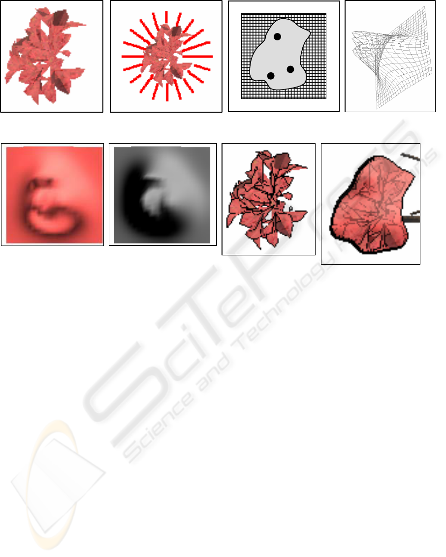
c) Place regional centers, 3D
screen-aligned blob mesh
h) Final blob billboard
d) Blob mesh (viewed
from the side)
b) “Shrink wrap” leaf group
in image plane
a) Render leaf group
f) Blob geometry rendered
with blend lighting (alpha
blend mask)
e) Blob mesh rendered with
average leaf group color,
scene lighting
g) Rendered original 3D
geometry
Figure 4: Creating a single blob. First we render the geometry and shrink wrap it in image space. Second, we construct the
approximate 3D blobgeometry. This geometry is a screen aligned height with the height field pointing in the direction of the
viewer. This geometry is used to create two images. The first image is the approximate, cartoon-like, rendering. The second is
the alpha-blend mask used to blend between the approximate image and the detailed image. This image becomes a billboard,
trimmed to the shrink wrapped blob outline.
a screen-aligned height field, with the height field
pointing towards the user. A 10 by 10 unit mesh
square, sufficient to make a smooth-looking blob, is
positioned where the leaves are in 3D space, oriented
to face the viewer. The height is one unit. The mesh is
then scaled so that it covers the leaves in screen space.
To create the height field we place three Gaussian
peaks inside of the blob boundary. To find the centers
of the peaks, we take the control points of the outline
and divide them into thirds. The average point of one
third of the boundary is then averaged with the center
point of the entire blob to move it slightly inwards.
The color wash used for the blob is an average of
the leaf texture color. The blob geometry is rendered
using the same lighting that is used to render the tree
(see fig 5e).
4.2.2 Adding Detail
The detail texture is created by rendering the leaves.
To emphasize the detail in the leaves, we optionally
let the user highlight the silhouette (Raskar and Co-
hen, 1999) edges of each leaf. This emphasizes the
outline of the leaf and deemphasizes the texture of the
leaf. The silhouette color can vary from black to the
average color of the leaf to white.
To create a combination of photorealism and non-
photorealism, the blob image and the detailed leaves
are blended together. An alpha blend mask is used
to determine how and where to blend. This mask is
created by rendering the blob geometry (colored grey)
with a set of blend lights. Dark regions get the detail
image, light regions the blob one. The user can select
the location of the light and the strength of the light.
At this point there are several saved images: An
image of the leaves with edges (see fig 3), an image
of an outline (see fig 3h), an image of the shape ap-
proximation (see fig 3e), and an image used to calcu-
late the alpha blend mask (see fig 3f). All of these
images are combined into a single image (see fig 3h)
which serves as a billboard image for the group. The
billboard image is clipped to the outline.
To help differentiate neighboring blobs, an outline
GRAPP 2007 - International Conference on Computer Graphics Theory and Applications
200
a) Render trunk and
branches (up to user-
specified level)
b) Blob is rendered as
billboard Billboard depth is minimum depth of corresponding leaf group
Figure 5: Combing branches and blobs into single image.
is drawn around the blob. The color of the outline
is user-controlled blend of the color of the blob and
black (or white). The thickness of the outline is con-
trolled by direction. When the edge is to the left of
a blob image pixel, the outline is drawn wider than if
the edge is in a different direction. A varying thick-
ness provides a greater feeling of depth.
The Painter’s algorithm (Newell et al., 1972) is
used to composite the individual blob images together
(since all of the blob images are screen aligned). The
depth of the blob is determined from the minimum
depth value of any leaf in the blob.
5 ANIMATION
An advantage of computer graphics over traditional
handpainted images is that moving the camera around
the scene is “free”. The biggest challenge is to main-
tain inter-frame image continuity. Rendering each
frame individually causes the boundaries of blobs to
jump, regional centers to bounce around, and blobs to
pop in and out as the depth changes between frames.
To solve these problems, we generate new blobs every
nth frame, then interpolate depth and shape informa-
tion between those frames.
5.1 Pre-rendering
To pre-render, we assume a pre-defined camera path.
A completely new frame is calculated every nth
frame, for a user-defined n. Between the nth frames
the control points for the blob outline and the depth
are interpolated. The regional centers for each blob
remain fixed relative to the changing size of the blob.
The detailed rendering is generated for each frame.
The number of control points used in the bound-
ary is the same between all blobs in all frames. The
boundary between the control points is interpolated
using a cubic B-spline, as is the location of the con-
trol points at each frame.
For each blob in each key frame the minimum
Frame 1 Frame 3 Frame 5
Frame 7 Frame 9 Frame 10
Figure 6: Depth blending over 9 frames.
depth of the leaves in the blob is determined. If one
blob will pass in front of another, we alpha blend be-
tween the two blobs over a period of n frames. This
prevents one blob from “popping” in front of the other
(see figure 6).
6 RESULTS
In this section we show examples of renderings for a
tree and a bush. We compare adjusting parameters for
the number of control points, light settings for alpha
blob, and color settings for outlines. There is an at-
tached movie that includes rotating and zooming sam-
ples of the results.
The first test subject used is a tree. This tree used
a division diameter of 0.042443. The division diam-
eter automatically generates the groupings of leaves
by measuring the diameter of branches. Twenty con-
trol points were used. The edges are black. The alpha
blending controls were set to 70% diffuse, 0% ambi-
ent, and the light position was to the right and up.
The second test subject used is a bush. This bush
used a division diameter of 0.068513. Twenty con-
trol points were used. The edges are black. The alpha
NON-PHOTOREALISTIC RENDERING OF ALGORITHMICALLY GENERATED TREES
201

Figure 7: Bush rendering.
blending controls were set to 70% diffuse, 0% ambi-
ent, and the light position also to the right and up.
The rendering time per frame is approximately
one minute if a purely software-based renderer is
used. This time is proportional to the number of ren-
dered blobs. A tree with approximately 8 blobs takes
30 to 45 seconds to render, while 20 blobs takes 60 to
90 seconds to render.
The number of control points used in the outline
effects the smoothness of the blob shapes (see fig-
ure 8).
The user can also control where detail is placed on
the blob by placing a “blending” light relative to the
view point. The scene is rendered and the brightness
used to control where the detail is placed. Brighter
spots will have less detail then darker ones (see Fig-
ure 9).
The user can also adjust the color of the blob out-
line and the silhouette of the leaves. The images in
figure 10 illustrate three different settings. Please re-
fer to the attached video. The video shows short clips
of the tree and bush rotating and zooming.
7 DISCUSSION
Trees are an ideal subject for abstraction because they
have both detail and gross structure, and it is fairly
easy to extract this gross structure from the 3D data
in a useful way. Unlike most non-photorealistic tech-
niques, this one replaces the 3D geometry with a sim-
pler 2.5D approximation, rather than applying filter-
ing. Applying this approach to other geometry, such
as mountains or flowers, would require specifying an
appropriate two or three dimensional geometry sim-
plification.
ACKNOWLEDGEMENTS
Thank you to the L-Studio group for the use of their
software. This research was funded in part by NSF
grant CCF-0238062.
REFERENCES
Boddy-Evans, M. (2005). Painting trees: A tips for render-
ing realistic and believable trees. About.com.
Bourdet, S. D. (2001). Painting The Allure of Nature. North
Light Books.
Deussen, O., Hiller, S., van Overveld, C., and Strothotte, T.
(2000). Floating points: A method for computing stip-
ple drawings. Computer Graphics Forum, 19(3):40–
51.
Deussen, O. and Strothotte, T. (2000). Computer-generated
pen-and-ink illustration of trees. In Siggraph 2000,
pages 13–18.
Di Fiore, F., Van Haevre, W., and Van Reeth, F. (2003).
Rendering artistic and believable trees for cartoon an-
imation. In Proceedings of Computer Graphics Inter-
national (CGI 2003), pages 144–151.
Francis, E. M. (2002). L-system.
Freudenberg, B., Masuch, M., and Strothotte, T.
(2002). Real-time halftoning: a primitive for non-
photorealistic shading. In EGRW ’02, pages 227–232.
Karwowski, R. and Lane, B. (2004). L-studio/lpfg: A soft-
ware system for modeling plants.
Kowalski, M. A., Markosian, L., Northrup, J. D., Bourdev,
L., Barzel, R., Holden, L. S., and Hughes, J. (August
1999). Art-based rendering of fur, grass, and trees.
Proceedings of SIGGRAPH 99, pages 433–438.
Lovett, J. (2004). How To Paint Trees.
Luft, T. and Deussen, O. (2006). Real-time watercolor illus-
trations of plants using a blurred depth test. In NPAR,
pages 11—20.
Markosian, L., Kowalski, M. A., Trychin, S. J., Bourdev,
L. D., Goldstein, D., and Hughes, J. F. (1997). Real-
time nonphotorealistic rendering. SIGGRAPH 1997,
31:415–420.
Meier, B. J. (1996). Painterly rendering for anima-
tion. Computer Graphics, 30(Annual Conference
Series):477–484.
Newell, M. E., Newell, R. G., and Sancha, T. L. (1972). A
solution to the hidden surface problem. In ACM’72,
pages 443–450.
Ostromoukhov, V. (1999). Digital facial engraving. In Pro-
ceedings of the 26th annual conference on Computer
graphics and interactive techniques, pages 417–424.
Prusinkiewicz, P. (2004). Art and science of life: Design-
ing and growing virtual plants with l-systems. In ISHS
Acta Horticulturae 630, pages 15–28. Acta Horticul-
turae.
Raskar, R. and Cohen, M. (1999). Image precision silhou-
ette edges. In I3D ’99, pages 135–140.
Smith, A. R. (1984). Plants, fractals, and formal languages.
In SIGGRAPH ’84, pages 1–10.
GRAPP 2007 - International Conference on Computer Graphics Theory and Applications
202
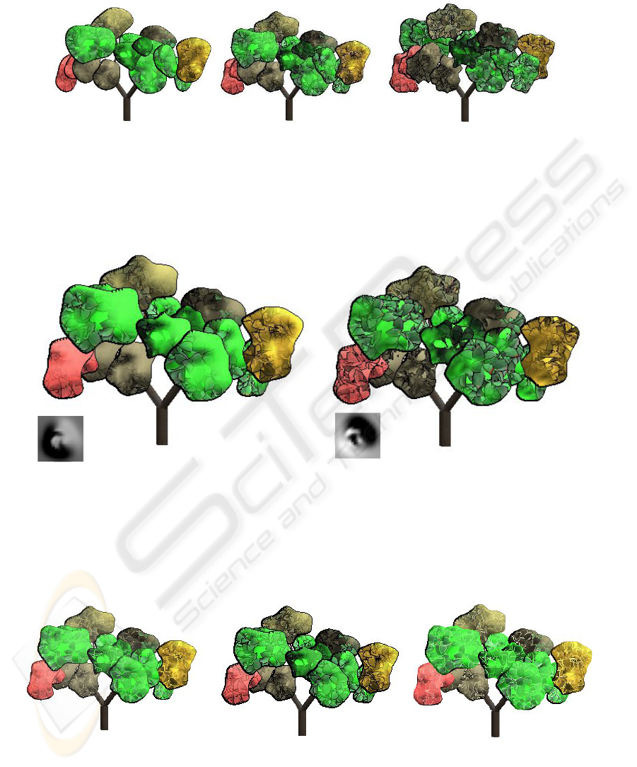
a) 10 points b) 20 points c) 30 points
Figure 8: Number of control points used to create outlines. (a) 10 control points. (b) 20 control points. (c) 30 control points.
b) Blend light lower left
a) Blend light upper right
Figure 9: Blending light. (a) Blending light is placed above and to right of viewer. (b) Blending light if placed below and to
left of viewer.
Leaf edge silhouette: Average color
Blob outlines: Average color + black
Leaf edge silhouette: Black
Blob outlines: Black
Leaf edge silhouette: White
Blob outlines: Average color + black
Figure 10: Changing the silhouette rendering style.
NON-PHOTOREALISTIC RENDERING OF ALGORITHMICALLY GENERATED TREES
203
