
ADVANCED DIRECT MANIPULATION
OF FEATURE MODELS
Rafael Bidarra, Alex Noort
Faculty of Electrical Engineering, Mathematics and Computer Science, Delft University of Technology, The Netherlands
Daniel Lourenço, Pedro Oliveira
Instituto Superior Técnico, Technical University of Lisbon, Portugal
Keywords:
Feature modelling, direct manipulation, user interaction, handles, constraints.
Abstract:
In current commercial feature modelling systems, support for direct manipulation of features is not commonly
available. As a result, re-designing is time-consuming due to the inefficient feedback, the insight given is
rather poor, and user interaction often lacks intuitiveness. This is partly due to the lack of speed of current
constraint solvers, but also to deficient interactive facilities. In this paper, we argue that providing advanced
direct manipulation facilities for feature models is possible and can significantly speed up the product design
process, by giving designers a much more intuitive interface, with immediate feedback and deeper insight into
the consequences of each modelling action. An approach to such a direct manipulation interface is presented
that brings together the advantages of direct manipulation of feature models with the necessary emphasis on
fundamental feature modelling paradigms like feature parametrisation and feature validity maintenance. In
particular, it offers a powerful combination of various 3D handles for real-valued feature parameters, with a
preview overlay facility for all modelling operations. Details are provided on how this approach was success-
fully implemented in a prototype feature modelling system.
1 INTRODUCTION
Feature modelling is a design paradigm that comes
as an alternative to the traditional geometry-based de-
sign systems. The founding idea of feature modelling
is to focus the modelling tasks of the designer on a
higher level, facilitating the specification of many dif-
ferent aspects in a product model, and gaining insight
into their inter-relations (Shah and Mäntylä, 1995).
This is achieved by enabling the designer to associate
functional information to the shape information in the
product model.
Although one cannot find a consensual definition
of the concept of feature, one that nicely fits to this re-
search defines a feature as "a representation of shape
aspects of a product that are mappable to a generic
shape and are functionally significant for some prod-
uct life-cycle phase" (Bidarra and Bronsvoort, 2000).
In contrast to conventional CAD systems, in which
the design focus mainly lies on geometry, in a fea-
ture modelling system the designer builds a model
out of features, each of which has a well-defined se-
mantics. As an example, for manufacturing planning
purposes it would be appropriate to provide the de-
signer with features that correspond to the manufac-
turing processes available to manufacture the product
being designed (e.g. slots and holes).
Feature model semantics is mostly represented by
a variety of constraints. Constraints can be used in
feature modelling systems to express characteristics
of the model (e.g. to specify some feature faces to
be co-planar, or restrict a given dimension to a cer-
tain range). But, above all, constraints are used as the
internal constituents of features that express their se-
mantics (e.g. a hole feature could have constraints to
position and orient it, or constraints that express the
physical limits of the drilling machinery available).
Because of this central role of constraints, feature
modelling systems have to make an intensive use of
constraint solving techniques. In particular, geomet-
ric constraints and geometric constraint solving tech-
niques are very common.
To ensure that feature model semantics is main-
tained, the validity of the feature model has to be
130
Bidarra R., Noort A., Lourenço D. and Oliveira P. (2007).
ADVANCED DIRECT MANIPULATION OF FEATURE MODELS.
In Proceedings of the Second International Conference on Computer Graphics Theory and Applications - GM/R, pages 130-136
DOI: 10.5220/0002080301300136
Copyright
c
SciTePress

checked after each model modification. Feature
model validity is usually checked by solving the con-
straints in the model: a valid feature model is a fea-
ture model that satisfies all its constraints. Modelling
systems which guarantee feature model semantics to
be maintained throughout the modelling process are
called semantic feature modelling systems (Bidarra
and Bronsvoort, 2000). So constraints play an im-
portant role during model creation and modification.
Quite some research work has been done on tech-
niques to enable constraint solvers to be used in in-
teractive applications, such as user interface onstruc-
tion (Borning and Duisberg, 1986; Freeman-Benson,
1993; Hosobe, 2001), and geometric modelling sys-
tems (Hsu et al., 1997; van Emmerik, 1991). How-
ever, in current modelling systems, the specification
and the modification of feature parameters that de-
termine its position/orientation and its dimensions,
is still mostly done through the input of values in
dialog boxes, after which the model is updated ac-
cordingly (Parametric Technology Corporation, 2006;
SolidWorks Corporation, 2006; UGS Corporation,
2006). The main disadvantages of this approach are:
inefficient feedback, making the design task much
slower. Each time the designer changes the pa-
rameters of a feature he has to wait for the whole
system of constraints to be solved and only then
can he see the effect of his changes and check the
validity of the model.
lack of insight on the consequences of the modelling
operation. When changing a parameter the user
can only see the original and resulting model of
the operation. In other words, there is no ex-
plicit feedback on which features were affected
and how.
non-intuitiveness due to the fact that the user is sim-
ply editing values in dialog boxes that do not ex-
press how the feature is affected by the parameter.
As a result of these drawbacks, all too often designers
are forced into using a trial-and-error approach to find
the right feature parameter to be changed or to find the
right value for the parameter.
Good interactive facilities for direct manipulation
of features should always deal with the three draw-
backs mentioned above. In this research, we devel-
oped a new approach that allows the designer to se-
lect a parameter of a feature in the model, and sub-
sequently modify its value interactively, while be-
ing provided with real-time feedback on the conse-
quences of the operation. When the designer is sat-
isfied with the model, he can choose to provision-
ally accept the changes and, eventually, let the system
check the model validity.
The most crucial aspect of this approach consists
of being able to provide real-time feedback on the
changes effected to the feature model. Since this vi-
sual feedback has to be generated several times per
second to support interactive modification of a fea-
ture parameter value, all geometric constraints have to
be solved at that same pace. To achieve this, we de-
veloped a technique that (i) reduces the time needed
to solve a geometric model, (ii) can be applied with
a variety of constraint solvers, and (iii) can be eas-
ily implemented. This technique has been recently
presented in (Lourenço et al., 2006), which contains
a detailed description of our model compilation and
constraint solving approach, together with a perfor-
mance analysis of its prototype implementation.
In this paper we focus on how our approach solves
the other two drawbacks mentioned above. Through-
out the paper, we deal with the situation in which
a real-valued feature parameter that determines a di-
mension, or the position or orientation of a feature in
a feature model, is interactively manipulated by a de-
signer. All aspects of our approach described in the
paper were implemented in SPIFF, a prototype fea-
ture modeling system developed at Delft University
of Technology.
We first introduce various aspects involved in our
approach to direct manipulation of features (Section
2). Next we propose several types of feature han-
dles (Section 3), and describe how they are utilised to
yield advanced interactive facilities (Section 4). Fi-
nally, some conclusions are drawn (Section 5).
2 DIRECT MANIPULATION OF
FEATURES
Features can be modified by manipulating their para-
meters. Although a parameter of a feature can also
be a face of another feature to which it is attached,
or with respect to which it is positioned, this paper
only deals with manipulation of real-valued feature
parameters, such as the dimension of a feature, the
distance of a feature with respect to a face of another
feature, etc. An example of a through hole feature
with its parameters is given in Figure 1, showing the
typical entry fields for the various parameter values.
2.1 Feature Manipulation Phases
Direct manipulation of a real-valued feature parame-
ter consists of two phases. In the selection phase, the
parameter to be manipulated has to be selected. In
the interaction phase, the value of the parameter is
ADVANCED DIRECT MANIPULATION OF FEATURE MODELS
131
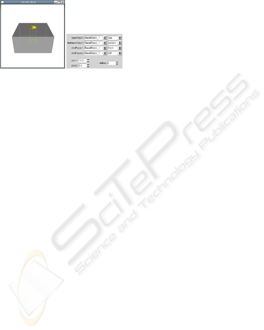
(a)
(b)
Figure 1: A through hole feature (a), and its parameters (b).
interactively changed by the designer, and the feature
model is updated accordingly by the system.
In the interaction phase, the designer changes the
value of a feature parameter, by using the mouse to
drag an icon that represents the feature parameter on
the displayed feature model. During the dragging, the
model and its visualization are updated continuously
to reflect the modifications.
The interaction phase needs to be performed real-
time, since the designer needs the feedback of the im-
age of the changed model on the display while drag-
ging the mouse. Real-time here means fast enough
to preserve the illusion of movement, i.e. the illusion
that consecutive images of the same object in a some-
what different position, show a moving object. This
illusion is preserved when the system displays more
than 10 frames (or images) per second (Card et al.,
1983).
2.2 Model Validity Maintenance
Manipulating the parameter of a feature in a model
may turn a valid feature model into an invalid one (see
Section 1), e.g. because an undesirable interaction oc-
curs between two features, or a dimension does not
satisfy its dimension constraint anymore.
An invalid situation should preferably be detected
during the manipulation of the model, and the de-
signer should preferably be immediately informed on
it. In case that it is not feasible to detect the invalid
situation during the manipulation of the model, for
example, because it takes too much time to check the
validity of the model, the validity of the model should
be checked as soon as the manipulation of the model
is ended.
However, in case a model has become invalid
during manipulation of a feature parameter, further
manipulation should not be prohibited, because the
model may turn valid again if the value of the parame-
ter is changed even more. For example, if the model
of Figure 1 would also contain a through slot that
is positioned to the left of the hole, and the through
slot would be moved to the right by manipulating its
position parameter, then, as the through slot and the
hole start to overlap, the model becomes invalid, but
the model turns valid again when the through slot is
moved beyond the hole.
If the model is invalid at the moment that the
manipulation of a feature parameter is ended, then
some validity maintenance mechanism (Bidarra and
Bronsvoort, 2000) should be triggered to assist the de-
signer to make the model valid again.
2.3 Constraint Management
To solve the geometric constraints in the model, a
constraint management scheme is used. The con-
straint management scheme maps a high-level con-
straint model, containing the complex design con-
straints, into a large low-level constraint model, con-
taining primitive constraints, that can be solved by
the constraint solvers used, and updates the high-level
constraint model based on the solved low-level con-
straint model.
Fortunately, in the interaction phase of direct ma-
nipulation, only part of the constraint model needs
to be solved. Since only one feature parameter is
changed during the interaction phase, typically, large
parts of the model do not change, i.e. they are rigid.
Such rigid parts can, therefore, be represented by a
single constraint variable in the low-level constraint
graph, thus avoiding the need to solve all constraints
within the parts.
Constraint managementfor interactive feature ma-
nipulation identifies all rigid parts of the model, and
maps each one to a separate constraint variable in the
low-level constraint model that is solved in the inter-
action phase. The resulting, simple, constraint model
is then used to find the relative position and orien-
tation of the rigid parts during the interaction phase,
given the current value of the feature parameter that
is changed. Again, this model compilation and con-
straint solving approach is described in (Lourenço
et al., 2006), to which the reader is referred for many
details on its fundamentals, implementation and per-
formance.
3 TYPES OF FEATURE HANDLES
Not all parameters of features have a direct geomet-
ric meaning. For such parameters, it is not possible
to assign a feature handle with a natural behaviour.
GRAPP 2007 - International Conference on Computer Graphics Theory and Applications
132
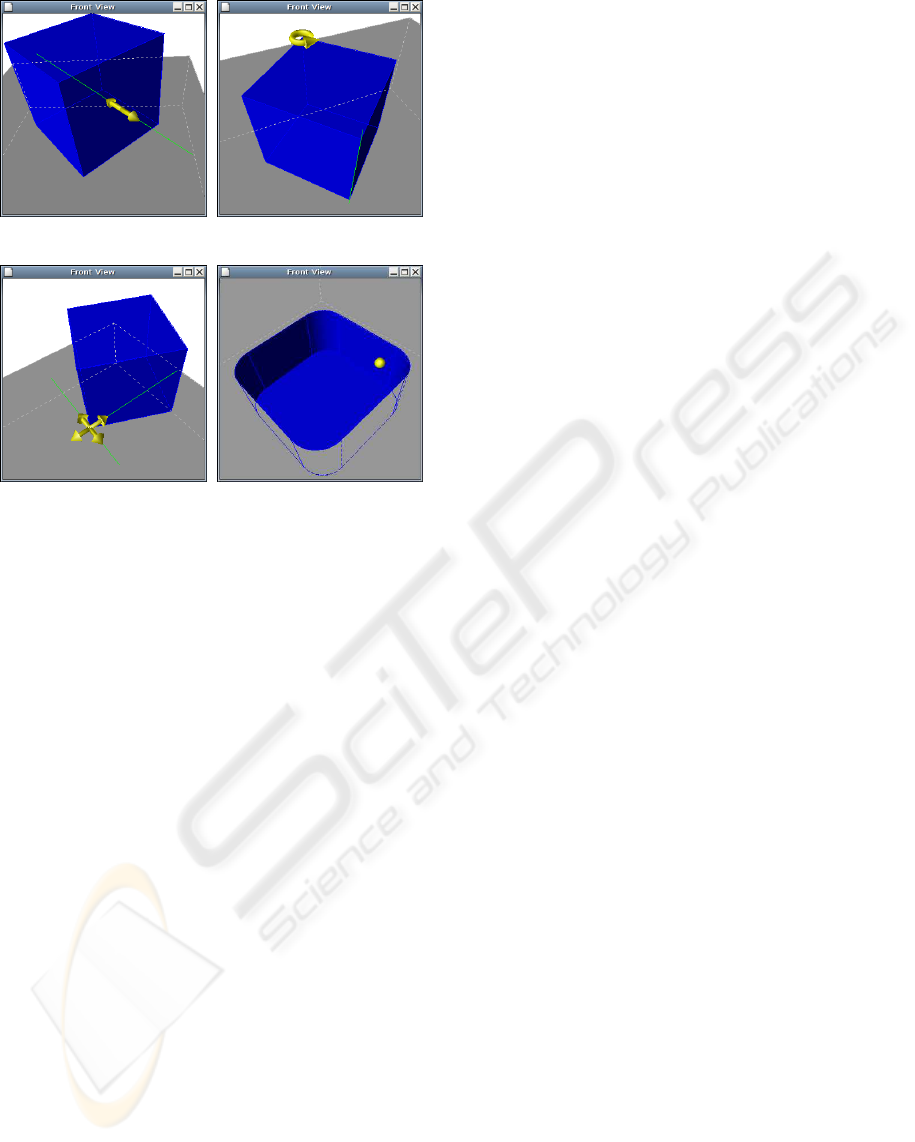
(a) Linear (b) Angular
(c) Planar (d) Slider
Figure 2: Types of handles.
A good example of this situation is a feature that has
a volume parameter. On the other hand, most para-
meters do have a simple geometric meaning, e.g. the
width of a protrusion or the rotation angle of the same
protrusion. As stated before, in this paper we deal
only with such real-valued parameters. For these, four
types of handles were identified that cover most direct
manipulation needs:
• Linear handles
• Angular handles
• Planar handles
• Slider handles
In this approach all handles of a feature are speci-
fied by their relation with reference elements (e.g. ref-
erence points and reference lines) of the feature. With
these references the system will be able to know the
placement of the handles as well as their behaviour
as they are being manipulated. One reference that is
needed for the specification of any type of handle is
the point that specifies its position in the model. These
references are specified at the feature definition like
any other references - using constraints. One very im-
portant consequence of the definition using references
is that the position and orientation of the handles will
be solely determined by the constraint solver.
We will now look with more detail into each of the
proposed handles:
• A linear handle is a handle that moves along a
straight line and reacts linearly with the mouse
movement. Besides the reference point represent-
ing the position, it also contains a reference line
representing the line on which the handle moves.
When the handle is dragged, the new mouse po-
sition is projected against the reference line, and
the parameter variation is given by the difference
between the computed position and the previous
position of the handle. See Figure 2(a).
• An angular handle is a handle that moves along
an arc in a way that the user is able to specify
an angle parameter. This handle has a reference
line besides the position reference that represents
the axis of rotation around which the angular han-
dle revolves. When the handle is dragged, the
new mouse position is projected onto the plane
perpendicular to the axis of rotation which passes
through the current position of the handle thereby
computing point1. To determine the change in the
parameter affected by this handle an angle is com-
puted. This angle is the angle between two lines in
the plane just mentioned which pass each through
the axis of rotation and through the original po-
sition of the handle and point1 respectively. See
Figure 2(b).
• A planar handle behaves somewhat like a linear
handle with the difference that, instead of having
its movement restricted to a line, its movement is
restricted to a plane (having two linear degrees
of freedom). For this type of handle two refer-
ence lines will be needed to determine the plane
on which it can move. One thing that differs from
this handle to all the others is the fact that by ma-
nipulating it the user is affecting two parameters
of the feature at the same time instead of one. To
determine the change in the parameter values a
computation similar to the one used for the lin-
ear handle will happen with the difference that the
mouse position will now be projected onto each
of the reference lines corresponding to each of the
parameters affected. The motivation for the exis-
tence of this handle is to enable the user to change
the position of features that have it specified by
two distances to external faces. See Figure 2(c).
• A slider handle is also similar to a linear handle
but, in this case, the line will simply be a vertical
line on the viewport with no connection to the ac-
tual feature geometry being changed by such pa-
rameter manipulation. Therefore this handle, un-
like any of the other handles, will contain solely
a reference point for its position and no reference
lines. The slider handle suits nicely to provide di-
rect manipulation to parameters that have no sim-
ADVANCED DIRECT MANIPULATION OF FEATURE MODELS
133
ple nor easy-to-localize geometric meaning, as the
corner radius in the pocket of Figure 2(d).
By combining these four kinds of handles in fea-
ture class definitions, the parameterization of a large
variety of feature classes is easily made ready for the
advanced direct manipulation facilities described in
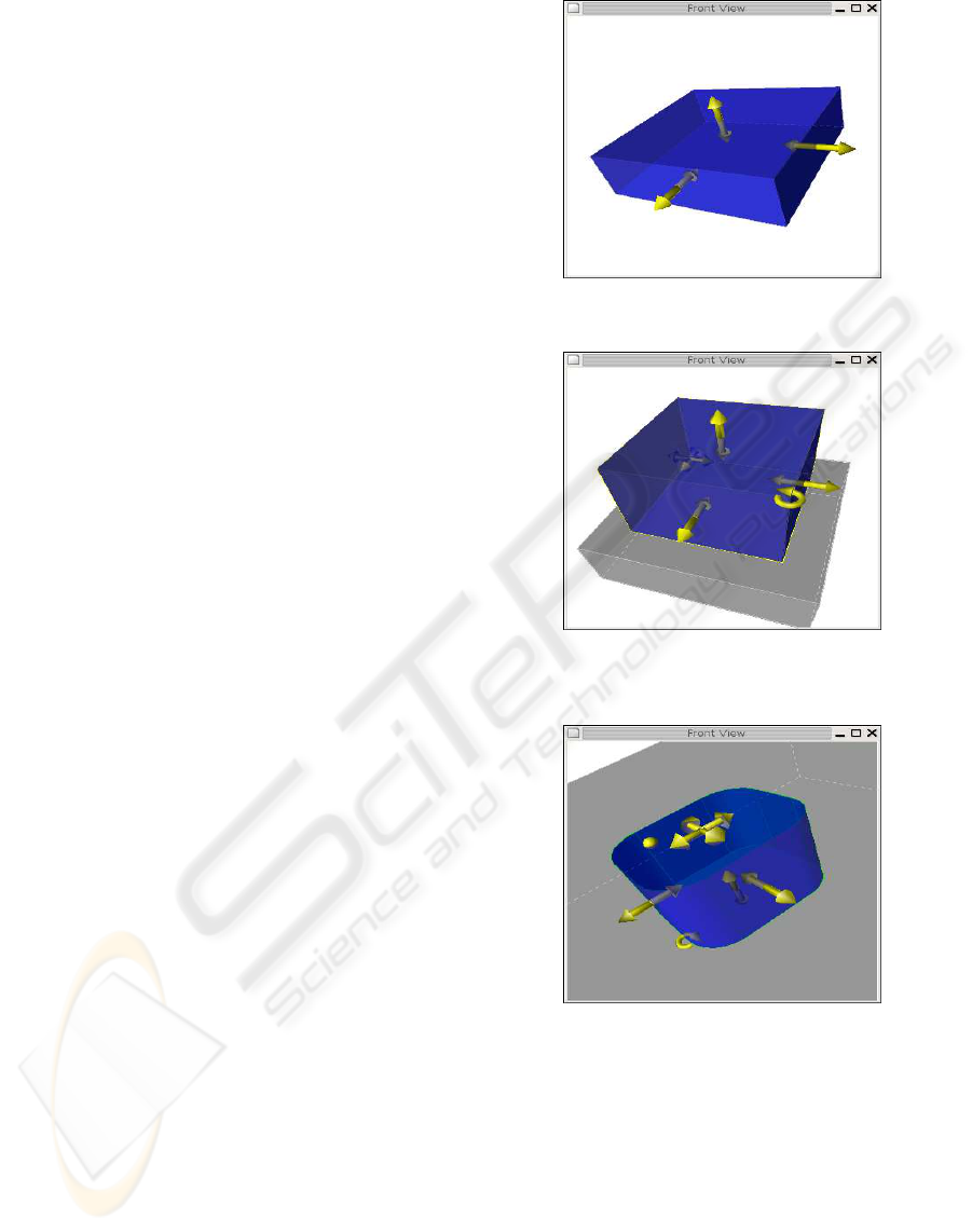
the next section. Figure 3 shows a few examples of
such feature classes.
4 ADVANCED INTERACTIVE
FACILITIES
The direct manipulation approach developed should
overcome the three disadvantages of traditional fea-
ture manipulation mentioned in Section 1. In other
words, it is required that (i) feedback is efficient,
(ii) that insight into the modelling operation conse-
quences is provided, and (iii) that the relation between
what’s manipulated and the way it affects the feature
becomes intuitive. In this section we describe how
this was achieved.
For efficient feedback every modelling operation
leads to an immediate preview of the result of the op-
eration to the user. This preview is provided through
a transparent overlay display of the resulting model.
The user has insight on the consequences of the oper-
ation, which become clear through the comparison of
the original model with the simultaneously displayed
preview. The manipulation is intuitive because of the
feature handles’ characteristics. The deployed feature
handles (see Section 3) take into account that each
feature parameter has a specific semantics. This se-
mantics will be expressed through the handle’s behav-
iour, positioning and iconic representation.
We now give a brief description of how the user
interacts with the feature model under this approach,
in a way that materializes the requirements presented
previously. For this, the example given in Figure 4
will be used.
• When a user selects a feature to be edited it is
highlighted with a transparent overlay with a dis-
tinguishing color and its available handles are dis-
played on the screen; see Figure 4.(b).
• The user may then edit the handles by dragging
them. When the user does so the display is up-
dated according to the change in the parameter.
When this happens, all the features which were
affected by the variation of the parameter also ap-
pear as a transparent overlay; ; see Figure 4.(c).
These changes are not final and can be undone.
• When the user chooses to Apply the modelling
operations, changes which have been made (and
(a) Base Block feature with handles for
width, height and length
(b) Block Protrusion feature with han-
dles for width, height, length, rotation
and position
(c) Rounded Rectangular Pocket feature
with handles for width, height, length,
rotation, position and corner radius
Figure 3: Examples of handle specifications for three dif-
ferent feature classes.
highlighted) previously become final and the full
model display is updated with the new parameter
values; see Figure 4.(d).
• When the user chooses to Dismiss the modelling
operation, the changes which have been made
GRAPP 2007 - International Conference on Computer Graphics Theory and Applications
134
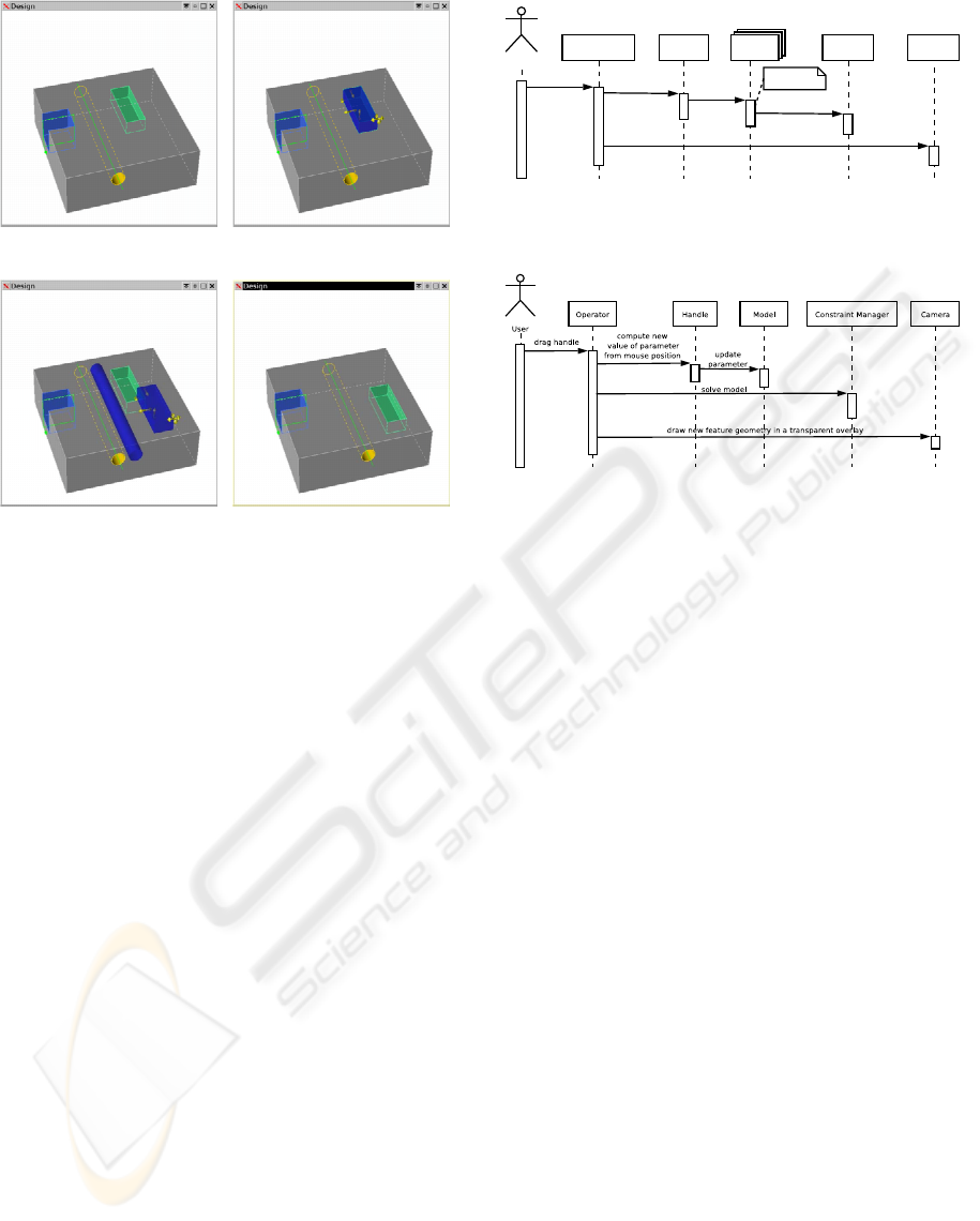
(a) Initial model (b) selection of the pocket
(c) dragging of the pocket (d) Final model
Figure 4: Interactively modifying a feature: the through
hole, positioned relatively to the pocket, is highlighted and
dragged together with it.
since the last Apply are undone.
As described in Section 2.1, two important phases
exist in the flow of events for handle manipulation:
the selection phase, when the user selects a parameter
of a feature to be edited, and the interaction phase,
each time the respective handle is dragged.
Figure 5 is a high level diagram of the flow of
events that happens when the user selects a feature
to be edited. Here, the user selection leads to the ac-
tivation of all the handles of the feature – the handle
is displayed and registered in the Operator (a control
entity). The feature is also highlighted with a trans-
parent overlay.
The flow of events that results from a single drag
event of the user is depicted in figure 6. The drag
event is reported to the Operator with the information
of the new mouse position. The operator sends a mes-
sage to the Handle which leads to the computation of
the new value of the parameter and to its update in
the model. This computation is obviously done tak-
ing into account the handle behaviour (see section 3).
After the new value is set, the Operator orders the
Constraint Manager to solve the model. This solving
process is done with the incremental constraint man-
agement solution specially optimized for direct ma-
nipulation described in (Lourenço et al., 2006). The
simple idea of this process is to add a preprocessing
User
User Interface Handle
select feature
for editing
Feature
prepare to edit
activate
draw handle
Operator Camera
register handle
draw selected feature overlay
Figure 5: Interaction diagram of what happens when the
user selects a feature for editing.
Figure 6: Interaction diagram of what happens when the
user drags a handle.
step when a parameter is first manipulated that boosts
the constraint solving performance to further changes
in that same parameter. With the new model values re-
sulting from the constraint solving process a transpar-
ent preview of the result of the operation is rendered
and displayed.
5 CONCLUSIONS
In this paper a new approach to the direct manipula-
tion of feature models was presented. Several types
of handles for parameters with a simple and intuitive
geometric meaning were introduced. In addition, a
slider handle was developed, for situations in which
the feature class designer wants to add direct ma-
nipulation to a generic parameter lacking an easy-to-
localize geometric meaning. The main aspects of the
new approach were discussed, together with its pro-
totype implementation within the SPIFF feature mod-
elling system, demonstrating its value and feasibility.
The definition of handles at the feature class level
is such that handles only depend on reference ele-
ments that are specified as any others in the system.
This solution has the advantage of having the posi-
tion and orientation of handle references automati-
cally computed in the constraint solving process.
For an effective and insightful feedback on the
modelling operations, a transparent preview of the
model is overlaid as the user directly manipulates a
feature through its handles. In this way the user can
ADVANCED DIRECT MANIPULATION OF FEATURE MODELS
135

clearly see the effects of the modelling operations and
compare the result with the original situation.
The prototype implementation has been success-
ful in making the manipulation of feature models a
very intuitive process, effectively improving the user
experience and, therefore, confirming the high poten-
tial of the approach.
REFERENCES
Bidarra, R. and Bronsvoort, W. F. (2000). Semantic feature
modelling. Computer-Aided Design, 32(3):201–225.
Borning, A. and Duisberg, R. (1986). Constraint-based
tools for building user interfaces. ACM Transactions
on Graphics, 5(4):345–374.
Card, S., Moran, T., and Newell, A. (1983). The Psychology
of Human-Computer Interaction. Lawrance Erlbaum
Associates, Hillsdale, N.J.
Freeman-Benson, B. N. (1993). Converting an existing
user interface to use constraints. In Proceedings of
the ACM Symposium on User Interface Software and
Technology, pages 207–215. ACM Press.
Hosobe, H. (2001). A modular geometic constraint solver
for user interface applications. In Proceedings of the
14th annual ACM symposium on User interface soft-
ware and technology, pages 91–100. ACM.
Hsu, C., Huang, Z., Beier, E., and Brüderlin, B. (1997).
A constraint-based manipulator toolset for editing 3d
objects. In Proceedings of the fourth ACM symposium
on Solid modeling and applications, pages 168–180.
ACM.
Lourenço, D., Oliveira, P., Noort, A., and Bidarra, R.
(2006). Constraint solving for direct manipulation
of features. Journal of Artificial Intelligence for
Engineering Design, Analysis and Manufacturing,
20(4):369–382.
Parametric Technology Corporation (2006).
Pro/ENGINEER product information.
http://www.ptc.com.
Shah, J. J. and Mäntylä, M. (1995). Parametric and
Feature-based CAD/CAM. John Wiley & Sons, Inc.,
New York.
SolidWorks Corporation (2006). Solidworks 2006 product
information. http://www.solidworks.com.
UGS Corporation (2006). Unigraphics NX product infor-
mation. http://www.ugs.com.
van Emmerik, M. J. G. M. (1991). Interactive design of 3D
models with geometric constraints. The Visual Com-
puter, 7(5/6):309–325.
GRAPP 2007 - International Conference on Computer Graphics Theory and Applications
136
