
A
UTONOMOUS MODEL-BASED OBJECT IDENTIFICATION &
CAMERA POSITION ESTIMATION WITH APPLICATION TO
AIRPORT LIGHTING QUALITY CONTROL
James H. Niblock, Jian-Xun Peng, Karen R. McMenemy and George W. Irwin
Queen’s University Belfast, School of Electronics, Electrical Engineering and Computer Science
Ashby Building, Stranmillis Road, Belfast, N. Ireland, BT9 5AH
Keywords:
Model-based object tracking, camera position estimation.
Abstract:
The development of an autonomous system for the accurate measurement of the quality of aerodrome ground
lighting (AGL) in accordance with current standards and recommendations is presented. The system is com-
posed of an imager which is placed inside the cockpit of an aircraft to record images of the AGL during a nor-
mal descent to an aerodrome. Before the performance of the AGL is assessed, it is first necessary to uniquely
identify each luminaire within the image and track it through the complete image sequence. A model-based
(MB) methodology is used to ascertain the optimum match between a template of the AGL and the actual
image data. Projective geometry, in addition to the image and real world location of the extracted luminaires,
is then used to calculate the position of the camera at the instant the image was acquired. Algorithms are
also presented which model the distortion apparent within the sensors optical system and average the camera’s
intrinsic parameters over multiple frames, so as to minimise the effects of noise on the acquired image data
and hence make the camera’s estimated position and orientation more accurate. The positional information is
validated using actual approach image data.
1 INTRODUCTION
Airport landing lighting has evolved from the early
beginnings when an aircraft’s relatively haphazard ar-
rival back to ground was conducted by the light of
gooseneck flares. Rapid development took place be-
tween 1939 and 1945, when the Drem
1
system was
evolved; and subsequent post war developments in
omnidirectional low intensity approach lighting cul-
minated in the present state of the art, where high
intensity Calvert systems are the order of the day-or
rather night (Milward, 1976).
These lighting systems have evolved in the last
number of years in order to guide the pilot onto the
runway safely. Since the earliest days of flying, pi-
lots have used ground references for navigation when
approaching an airport. Pilots need these visual aids
in good weather, as well as bad, and during the day
as well as at night (Horonjeff and McKelvey, 1993).
When visibility is poor and in night time conditions,
1
Drem
Lighting System was developed to assist Spitfire
landing in WW2
the visual information is reduced significantly when
compared to the clear-weather daytime scene. It is
therefore essential to provide visual aids which are
as meaningful to pilots as possible (Horonjeff and
McKelvey, 1993). Today’s state of the art lighting
is referred to as aerodrome ground lighting (AGL)
and consists of approach lighting, elevated above the
ground, to guide the pilot onto the runway lighting
pattern and taxi the aircraft into its terminal. In or-
der to ensure the consistency of an airport lighting in-
stallation, strict guidelines are enforced on the posi-
tioning, uniformity, colour and intensity of the lumi-
naires
2
that make up the complete AGL.
The International Civil Aviation Organisation
(ICAO) has published a recommendation that the
measurement of luminous intensity, beam spread and
orientation of the luminaires, included in the approach
and runway lighting systems for a precision approach
2
A
complete lighting unit consisting of a lamp or lamps
together with the parts designed to distribute the light, to
position and protect the lamps and to connect them to the
power supply.
383
H. Niblock J., Peng J., R. McMenemy K. and W. Irwin G. (2008).
AUTONOMOUS MODEL-BASED OBJECT IDENTIFICATION & CAMERA POSITION ESTIMATION WITH APPLICATION TO AIRPORT LIGHTING
QUALITY CONTROL.
In Proceedings of the Third International Conference on Computer Vision Theory and Applications, pages 383-390
DOI: 10.5220/0001085503830390
Copyright
c
SciTePress
runway category I/II/III, should be undertaken using a
mobile measuring unit of sufficient accuracy to anal-
yse the characteristics of the individual luminaires.
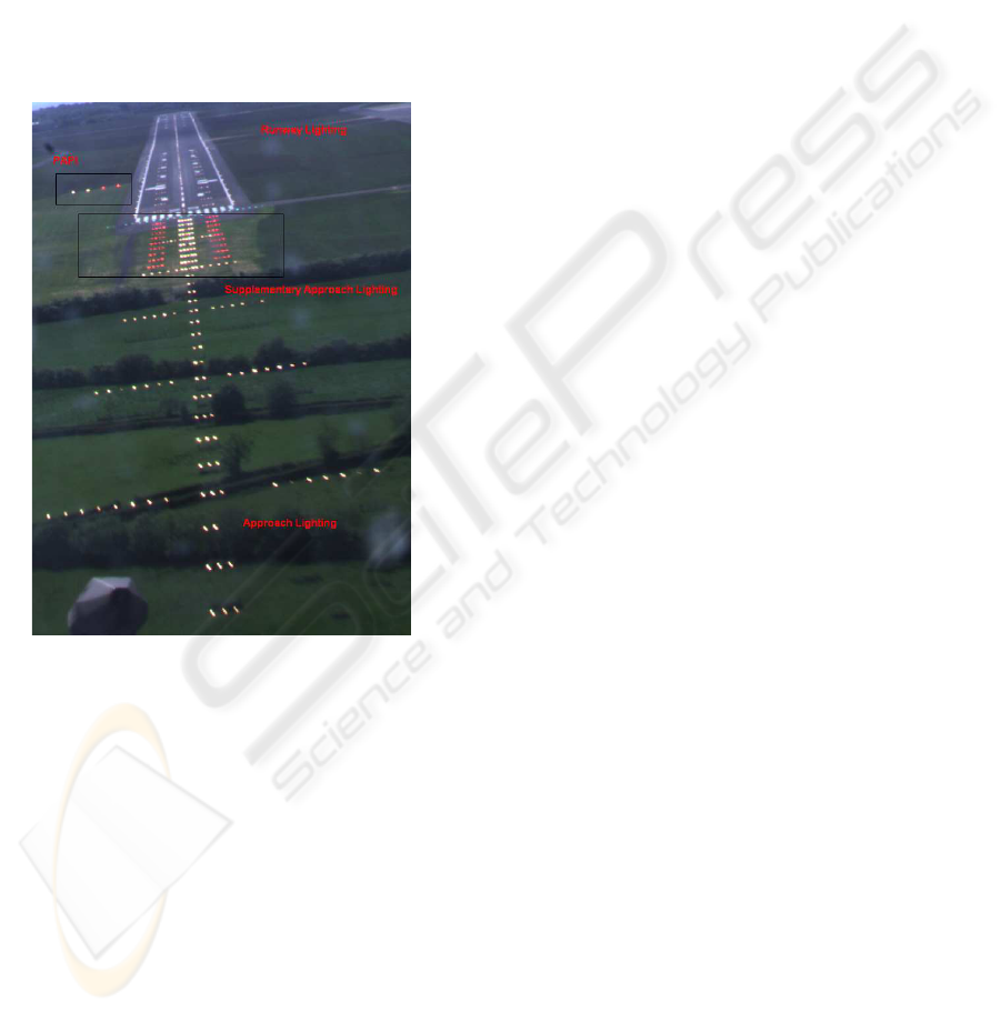
To assess the performance and alignment of the lu-
minaires it is necessary to know more about the AGL
and how the luminaires are arranged. AGL consists of
runway lighting separated from the approach lighting
system (ALS) by a row of luminaires termed the run-
way threshold. Runway and threshold luminaires are
usually inset, that is, they are installed at ground level
whilst the approach luminaires are elevated above the
ground. A typical AGL (CATI (ICAO, 2004)) layout
is illustrated in figure 1.
Figure 1: AGL Layout.
This paper presents results from research con-
ducted into creating an aerial-based vision system ca-
pable of autonomous performance assessment of the
complete AGL pattern. The work proposes mounting
one, or more, cameras in the aircraft, capable of ac-
quiring image data of a descent to the airport as the
aircraft performs a landing. The function of the cam-
era is to replicate what the pilots see during a standard
approach and store the information to an external hard
drive for off-line performance assessment.
To assess the performance of luminaires a number
of processes need to be undertaken. Firstly, the noise
apparent in the camera needs to be quantified in the
form of a distortion matrix. The next problem is that
of uniquely identifying each luminaire from the ac-
quired image data. Niblock et al. compared a basic
single pixel image-based tracking method against ex-
isting tracking techniques, such as, the KLT and SIFT
alternatives (Niblock et al., 2007a). This work high-
lighted the limitations of such a tracking system and
proposed that in order to uniquely identify each lumi-
naire, and thus assess its performance, a model-based
approach is required.
In this paper the model-based tracker is briefly dis-
cussed before showing how this technique was up-
dated for the purposes of camera position and pose
determination. The model-based approach attempts
to match a template of the ALS to the set of extracted
luminaires from the image, where the template of the
ALS is illustrated in figure 2. Strict standards en-
forced by the ICAO (ICAO, 2004) are in place for the
positioning, uniformity, projection angle and colour
of these luminaires.
The major advantage of this approach, is that for
each successfully matched luminaire, information re-
garding its position is known, both within the image
and real-world coordinate frames. Therefore, projec-
tive geometry can be utilised to estimate the camera
position and orientation data at the instant each image
was acquired. It is essential in this work to have ac-
curate camera position and pose information for the
luminaire performance assessment. Existing research
indicates that an image of a luminaire can be used to
estimate the intensity of a luminaire, providing accu-
rate position and orientation of the camera in relation
to the luminaire is known (McMenemy, 2003). The
contribution of the paper is to present a model-based
methodology for luminaire identification which is ex-
tended in order to estimate the position and orienta-
tion of the camera (aircraft) during its descent. The
theory is validated using actual approach data before
concluding remarks and future work are discussed.
2 MODEL-BASED (MB)
TRACKING
In order to assess the performance of the luminaires
it is first necessary to uniquely identify each lumi-
naire in the ALS and track them through an image
sequence in order to build up a profile of the lighting
pattern. Once the luminaires have been identified and
labelled, these features are then used to estimate the
camera’s position during the landing. It is essential
that the estimated camera position is accurate and ro-
bust to noise as any inaccuracies will have a follow on
effect with the performance assessment software.
The objective of the MB tracker is one of trying
to match a template which consists of the luminaires
within the ALS to a set of features extracted from im-
age data acquired during the approach to the airport.
VISAPP 2008 - International Conference on Computer Vision Theory and Applications
384
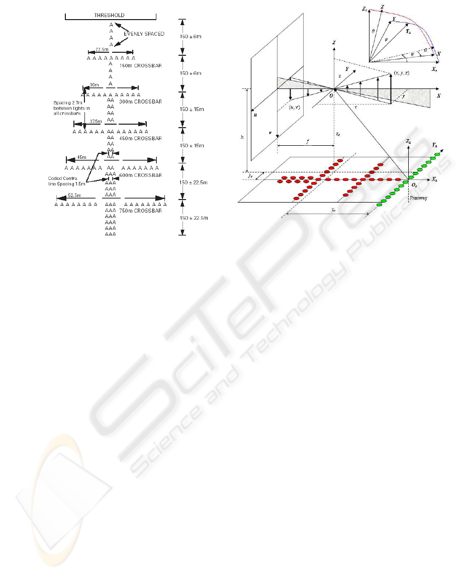
Figure 2: Standard Category I (CATI) approach lighting
pattern.
This process is known as planar homography and con-
sists of finding a one-to-one match between a pair of
images (Vincent and Laganiere, 2001) or, in this case,
a template of the ALS and an image.
In order to project this template onto the acquired
image data a pinhole camera projection system is
utilised which is mathematically modelled as consist-
ing of a projection system and an imaging system.
The projection system projects a 3D-object from the
real world (i.e. an ALS luminaire) to the image plane
of the camera. The imaging system converts the pro-
jected 2D-object on the image plane into a series of
pixels through an image sensor array.
According to the pinhole imaging principle de-
picted in figure 3 a 3D-point (x, y, z) expressed in the
camera coordinate system OXY Z is projected to a 2D-
point (u,v) on the image plane using a projection sys-
tem. From figure 3 we can summarise (1).
u = f x
−1
y
v = f x
−1
z
¾
(1)
where f denotes the focal length of the camera. It
is necessary to allow the focal length of the cam-
era to vary so that the camera will be capable of au-
tonomously locating the AGL and zooming in on the
relevant area of the lighting pattern, for example the
ALS. This process enhances the quality of the ac-
quired image data.
Assuming that the image sensor array is evenly
configured as orthogonal grids, that is to say a se-
Figure 3: Model-based projection system.
ries of rectangular-shaped pixels aligned in a grid-
like structure in the image plane, the imaging system
can then be represented as the linear transformation
shown in equation (2),
b
p = k
u0
+ k
u
u = k
u0
+ α
u
x
−1
y
b
q = k
v0
+ k
v
v = k
v0
+ α
v
x
−1
y
¾
(2)
where (
b
p,
b
q) denotes the coordinates of the pixel cor-
responding to the 2D-point projection (u,v) in the im-
age plane given in (1); k
u
and k
v
are the number of pix-
els per unit distance in the u and v directions respec-
tively, and α
u
= k
u
f , α
v
= k
v
f represent the intrin-
sic camera parameters, where f represents the focal
length of the imaging system and k
u
/k
v
represent the
scaling factor of the image data and the horizontal and
vertical image plane respectively. Finally, (k
u0
, k
v0
)
represent the image coordinates of the intersection of
the optical axis and the image plane, henceforth re-
ferred to as the principal point.
However, the approaching template is normally
defined with the 3D coordinates of the 120 luminaries
given in the airport coordinate system O
a
X
a
Y
a
Z
a
. The
transformation from the airport coordinate system to
the camera coordinate system includes a translation
and a rotation as shown in equation (3).
x
y
z
= R(γ, θ, ψ)
x
t
− x
o
y
t
− y
o
z
t
− z
o
(3)
where the translation o = [x
o
, y
o
, z
o
]
T
contains the co-
ordinates of the camera position (defined at the orig-
inal point of the camera coordinate system, see fig-
AUTONOMOUS MODEL-BASED OBJECT IDENTIFICATION & CAMERA POSITION ESTIMATION WITH
APPLICATION TO AIRPORT LIGHTING QUALITY CONTROL
385

ure 3) in the airport coordinate system. The vec-
tor t = [x
t
, y
t
, z
t
]
T
contains the coordinates of an ap-
proaching luminaire in the airport coordinate system
and (γ, θ, ψ) denote the yaw, pitch and roll of the cam-
era system respectively (i.e. the three rotations around
the X,Y and Z axis respectively). Where R(γ, θ, ψ) is
the corresponding rotation matrix, which is formed
by three rotations around the Z, Y and X axes respec-
tively of the camera coordinate system, as shown in
equation (4),
R(γ, θ, ψ) = R
x
(γ)R
y
(θ)R
z
(ψ)
R
x
(γ) =
1 0 0
0 cosγ sinγ
0 −sin γ cosγ
R
y
(θ) =
cosθ 0 −sinθ
0 1 0
sinθ 0 cosθ
R
z
(ψ) =
cosψ sinψ 0
−sin ψ cosψ 0
0 0 1
(4)
where R
z
(ψ), R
y
(θ) and R
x
(γ) are the corresponding
rotation matrices around Z, Y and X axes, respectively
(V. Lepetit, 2005).
Using the pin-hole camera projection system il-
lustrated in figure 3 the template of the ALS is su-
perimposed onto the image data and the Levenberg-
Marquardt (LM) method used to minimise the error
between the two sets of data. This procedure is de-
tailed by Niblock et al. (Niblock et al., 2007b) and
Peng et al. (Peng et al., 2006). Niblock et al. show
that this process works well and results in successfully
identified luminaires in the image sequence (Niblock
et al., 2007b).
The major advantage offered by a model-based
methodology is its ability to identify luminaires that
are missing (or have been turned off) in the ALS.
Techniques such as KLT and SIFT only track lumi-
naires that are present in the image data. It is essential,
for the performance assessment work, that if a lumi-
naire is missing, for any reason, that its position is still
recorded and its associated grey level stored. By us-
ing a template of the ALS this is made possible. Fur-
thermore, the model-based methodology produces the
best results on the actual image data (Niblock et al.,
2007b). As the noise level is increased, it is essen-
tial that the algorithms are more robust and have a
high tolerance level to noise inherent within the image
data. If this is not the case false matches can be made
and the grey level profiles of the extracted luminaires
can become confused, which is highly undesirable for
this application.
These identified luminaires can then be used to es-
timate the position and orientation of the camera at
the instant the image was taken, which as previously
mentioned is essential for luminaire performance as-
sessment.
2.1 Camera Positioning
Being able to estimate position and orientation infor-
mation from image data is a well researched area in
computer vision. Indeed, work has already been con-
ducted in the area of aircraft positioning by Soni et al.
(Soni and Sridhar, 1994) and Sridhar et al. (Sridhar
et al., 1996; Chatterji et al., 1998) who produced sys-
tems that utilise the information provided by the posi-
tion of individual luminaires in an image for estimat-
ing the relative position and orientation of an aircraft.
The location of luminaires within the image plane is
derived using perspective projection equations based
on a pinhole camera model (Faugeras and Toscani,
1987). Differences of features tracked between suc-
cessive images are used in conjunction with a recur-
sive optimisation algorithm in order to find the op-
timum position and orientation of the aircraft. The
drawback of Soni’s work is that the roll of the air-
craft is obtained using a roll sensor and is not ob-
tained, like the other variables, from the image se-
quence. Mostafavi et al. use similar techniques with
external information such as Differential Global Posi-
tioning System (DGPS) data in order to ascertain the
position and orientation of the camera with relation to
the runway outline and markers (Mostafavi and Mal-
one, 1995).
The work presented in this paper differs from the
aforementioned research by presenting novel tech-
niques which average the intrinsic camera parame-
ters over multiple frames, in order to minimise the
effects of noise inherent within the image data, and
thus make the estimated extrinsic parameters more ac-
curate. A further contribution of this work is that a
varying focal length may be used by the imaging sys-
tem is order to acquire image data of the highest qual-
ity, which is essential for the performance assessment
of the ALS. The previous work in this area, gener-
ally assume constant intrinsic parameters. To realise
an accurate imaging system, distortions caused by the
sensors optical system also need to be modelled and
accounted for.
2.2 Distortion Correction
The model outlined in section 2 makes a number of
assumptions regarding the optical system utilised by
the imaging system. If the acquired image data has
VISAPP 2008 - International Conference on Computer Vision Theory and Applications
386

been affected by distortion the image can change in
shape and thus the points are no longer assigned to the
pixel position that was estimated using the previous
model.
That is to say, for real cameras, a pure perspec-
tive projection model is not always sufficient to pre-
cisely represent the image data. Several types of im-
perfections in the design, machining and assembly of
the camera optical (lens) system may result in small
geometrical distortion (Heikkila, 2000). Most com-
monly the distortion errors are decomposed into ra-
dial (figure 4(c)) and tangential (figure 4(b)) compo-
nents (Faugeras and Toscani, 1987), where the perfect
undistorted image is illustrated in figure 4(a). For the
distorted image coordinates given by (r
d
, c
d
), the cor-
rected (or undistorted) coordinates are expressed as
equation (5).
c
u
= c
d
+ δ
c
(r
d
, c
d
)
r
u
= r
d
+ δ
r
(r
d
, c
d
)
¾
(5)
where (r
u
, c
u
) denote the distortion-free image co-
ordinates (that are unobservable) corresponding to
(r
d
, c
d
) that are observable in the actual image, and
δ
c
(r
d
, c
d
), δ
r
(r
d
, c
d
) denote the total displacements
along the column and row directions respectively.
Heikkila gives further details on image distortion and
the relevant tangential and radial distortion models
(Heikkila, 2000). Utilising these standard techniques
the distortion in the image data is corrected for, be-
fore any estimates of the camera position and orien-
tation are calculated. In addition to distortion correc-
tion, it is important to realise that the focal length of
the camera can vary during the approach. A change in
the focal length will obviously lead to a change in the
projection model, and thus it is necessary to account
for this. The algorithms to do this are now discussed.
2.3 Multi Frame-based Estimation
The objective of the multi frame-based estimation
technique is to create an algorithm that allows for a
varying focal length. The focal length is one of the
intrinsic camera parameters modelled in equation (2),
represented by the α
u
, α
v
coefficients. To do this, the
technique assumes that the intrinsic camera parame-
ters remain constant for a predefined time period, e.g.
1 second. Therefore, this work estimates the intrin-
sic camera parameters over a predefined number of
images and averages them in order to minimise error
caused by noise inherent within the acquired image
data. These optimised intrinsic camera parameters are
then used to estimate the camera’s position and orien-
tation (i.e. extrinsic parameters) during the landing.
Suppose a sequence of F
T
images are as-
sessed and the intrinsic parameters and distor-
tion coefficients of the camera are assumed con-
stant over the F
T
frames, denoted as w
int
=
[k
u0
, k
v0
, α
u
, α
v
, k
1
, k
2
, t
1
, t
2
]
T
, where w
int
represents
the intrinsic camera parameters, where (k
u0
, k
v0
) de-
notes the principal point of the image, (α
u
, α
v
)
are a combination of the focal length and res-
olution of the camera and the k, t coefficients
represent the radial and tangential distortion pa-
rameters respectively, as modelled by Lepetit et
al. (V. Lepetit, 2005). If the camera ex-
trinsic parameters for frame f
c
are denoted as
w
ext
( f
c
) = [t
x
( f
c
), t
y
( f
c
), t
z
( f
c
), ψ( f
c
), θ( f
c
), γ( f
c
)]
T
,
where (t
x
( f
c
), t
y
( f
c
), t
z
( f
c
)) represent the camera’s po-
sition in a given frame and (ψ( f
c
), θ( f
c
), γ( f
c
)) the
orientation, then the cost function is defined in equa-
tion (6) as,
E(w
ext
, w
int
) =
F
T
∑
f
c
=1
N
∑
k=1
[e
2
c
( f
c
;k)+ e
2
r
( f
c
;k)] (6)
where k = 1, ..., N and represents the number of ex-
tracted luminaires in the image. Equation (6) thus
needs to be minimised with respect to w
int
and
w
ext
( f
c
) for f
c
= 1, ..., F
T
,
e
c
( f
c
, k) = c(k)(w
int
, w
ext
( f
c
)) − c
u
( f
c
, k)(w
int
)
e
r
( f
c
, k) = r(k)(w
int
, w
ext
( f
c
)) − r
u
( f
c
, k)(w
int
)
¾
(7)
where r(k)(w
int
, w
ext
( f
c
)) and c(k)(w
int
, w
ext
( f
c
)) de-
note the projection coordinates of the k
th
ALS lumi-
naire produced in equation (8),
c = α
v
x
c
z
−1
c
+ k
v0
r = α
u
y
c
z
−1
c
+ k
u0
¾
(8)
which are functions of the intrinsic parameters w
int
and the extrinsic parameters w
ext
( f
c
) for frame
f
c
; r
u
( f
c
, k)(w
int
) and c
u
( f
c
, k)(w
int
) denote the
distortion-free image coordinates of the blob corre-
sponding to the k
th
luminaire extracted from frame
f
c
, which are functions of the intrinsic parame-
ters w
int
, or more specifically, functions of part
(k
u0
, k
v0
, k
1
, k
2
, t
1
, t
2
) of w
int
.
With an optimised multiple frame-based camera
parameter estimation now established, section 2.4 de-
tails the constraints applied to the software. Once
these constraints are defined the software is tested us-
ing actual airport lighting data.
2.4 Constraints
A number of constraints are placed upon the camera
positioning algorithms. When making a normal 3 de-
gree approach to the airport a number of assumptions
AUTONOMOUS MODEL-BASED OBJECT IDENTIFICATION & CAMERA POSITION ESTIMATION WITH
APPLICATION TO AIRPORT LIGHTING QUALITY CONTROL
387
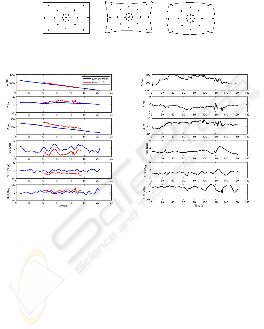
(a) (b) (c)
Figure 4: (a) Original image (b) Tangential distortion (c) Radial distortion.
Figure 5: Camera position and orientation for actual ap-
proach data using the multi frame-based estimation.
can be made. Firstly the camera starts to acquire im-
age data from roughly 2.5km from the airport. If a 3
degree approach is assumed this means that the height
of the aircraft with respect to the AGL is approxi-
mately 131m. Therefore, boundaries can be placed
on the X,Y and Z data, for example 2500±1000m,
0±50m and 150±150m respectively. However, if it
is not possible to assume a 3 degree approach and a
different angle of approach is used, then trigonometry
can be used to update the starting constraints and their
respective upper and lower limits. A second assump-
tion is that the field of view of the camera is set to 45
degrees. This assumption helps with the segmentation
of the ALS and ensures the noise from surrounding
light sources and general background illumination is
kept to a minimum.
With the optimised intrinsic camera parameters
estimated over multiple frames, the next section val-
Figure 6: Error profile for the camera’s position and orien-
tation for actual approach data using the multi frame-based
estimation.
idates the new software using actual airport lighting
data acquired during an approach to Belfast Interna-
tional Airport.
3 POSITION & ORIENTATION
RESULTS
During a complete flight test a number of approaches
are made to the airport. The vision system detailed in
this paper was mounted in the cockpit of the aircraft
and set to acquire image data during these approaches.
The algorithms detailed were used to uniquely iden-
tify each of the luminaires in the ALS before using
this information to estimate the aircraft’s position and
orientation during the approach. To assess the accu-
VISAPP 2008 - International Conference on Computer Vision Theory and Applications
388
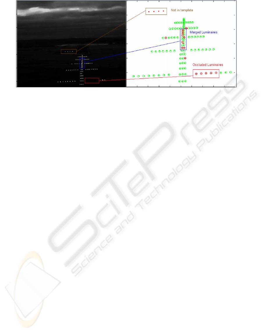
Figure 7: Missing/merged luminaires (left image) and optimisation results (right image). Note how the luminaires are still
identified by the model-based matching algorithm even though they are not present in the image data. (Niblock et al., 2007b).
racy of the proposed algorithms, they are compared
to the Flight Precision’s ILS position and orientation
data.
The successfully extracted luminaires were then
used to estimate the camera’s position and pose. The
model-based results for a sample image are shown
in figure 7. The dots represent extracted luminaires
present in the image data, using the connected com-
ponent analysis technique outlined in (Niblock et al.,
2007a). Most luminaires have been successfully iden-
tified and these are represented by the dot with a cir-
cle around it. However, a number of the circles have
a cross (‘+’) inside them, which indicates a luminaire
that is missing or hasn’t been extracted from the im-
age data. These can be caused by merged luminaires
(illustrated at the top of the image), or because the
luminaires are actually missing or occluded (as illus-
trated in the bottom right of the figure where 5 consec-
utive luminaires are occluded by a temperature meter
housed outside the aircraft).
Figure 5 shows how the camera parameters es-
timated using the multi frame-based software, com-
pared with the Flight Precision ILS data. The re-
sults show a good comparison in terms of the esti-
mated camera position. There is also a good corre-
spondence between the pose information. More im-
portantly there is a strong correlation between the pro-
files, with a constant offset apparent between the two
sets of position and pose data illustrated in figure 5.
The reason for this offset (and why both sets of data
are not superimposed on top of each other) is that the
ILS data shows the aircraft’s position and pose with
respect to the PAPI luminaires (illustrated in figure 2),
whereas the model-based positioning software calcu-
lates the position and pose of the camera with respect
to the centre of the threshold.
The error profile, which is the difference between
the two sets of data, is shown in figure 6. The fig-
ure shows that the positional error is largest for the
X parameter. Note that the errors shown in figure 6
include the constant difference between the two ref-
erence systems of the ILS and image-based data. For
example, with the camera pose information, the er-
ror between the two sets of data is negligible with the
highest error set at 5 degrees which is explained by the
two difference reference coordinate frames utilised. It
is also worth highlighting that the error profile is min-
imised because the camera’s intrinsic parameters are
averaged over multiple frames thus causing the error
of the camera’s extrinsic parameters (caused by fac-
tors such as stray noise) apparent in any given image
to be minimised.
4 CONCLUDING REMARKS
This paper presents results from research conducted
into creating an aerial-based vision system capable of
autonomous performance assessment of the complete
AGL pattern. The work proposes mounting one, or
more, cameras in the aircraft, capable of acquiring im-
age data during a typical descent to the aerodrome as
the aircraft performs a landing.
To date algorithms have been produced in order
to robustly extract the luminaires present within the
image data and identity them using a model-based
methodology. A pin-hole camera projection system
was then used to estimate the position and orienta-
tion of the camera, during the descent, from the ac-
quired image data. The results obtained from the new
software were compared against the positional infor-
mation supplied by the Flight Precision ILS data and
a strong correlation was found between both sets of
data. In particular the profiles of the two sets of posi-
AUTONOMOUS MODEL-BASED OBJECT IDENTIFICATION & CAMERA POSITION ESTIMATION WITH
APPLICATION TO AIRPORT LIGHTING QUALITY CONTROL
389

tional and orientation data were found to have a strong
correlation with the constant error offset explained by
the different reference systems utilised by both tech-
niques.
The final goal of this work is to realise an au-
tonomous image processing system capable of as-
sessing the performance of the complete AGL pat-
tern. Thus far, MATLAB has been used for the soft-
ware with a mean execution time per frame of ap-
proximately 3 seconds and a standard deviation of
0.3s/frame achieved using a standard CPU with a
3GHz processor and 1GB RAM. This timing infor-
mation could be dramatically reduced with a C++
setup and further reduced if the algorithms were pro-
grammed with a GPU as implemented by Sinha et al.
(Sinha et al., 2006).
Future work includes assessing the performance
of the lighting pattern. To this end two methodolo-
gies are proposed. Firstly, uniformity, which assesses
the performance of the complete lighting pattern and
secondly, assessing the luminous intensity of each in-
dividual luminaire within the lighting pattern. This
work will add negligible time onto the execution time
per frame as the memory inefficient and time con-
suming tasks of reading in an image sequence and
extracting the luminaires/eatimating the aircraft’s po-
sition have already been determined. Thus, this paper
shows that it is possible to assess the performance of
the AGL using an aerial-based imaging methodology.
ACKNOWLEDGEMENTS
The authors would like to thank the EPSRC (Grant:
EP/D05902X/1) for their financial backing for the
research (2004-2007) and the Royal Academy of
Engineering for their postgraduate fellowship award
(2005). Furthermore, we would also like to acknowl-
edge the contribution of Flight Precision and Belfast
International Airport for providing flight time in order
to collect airport lighting data and test the developed
algorithms.
REFERENCES
Chatterji, G., Menon, P., and Sridhar, B. (1998). Vision-
based position and attitude determination for aircraft
night landing. Journal of Guidance, Control, and Dy-
namics, 21(1).
Faugeras, O. and Toscani, G. (1987). Camera calibration
for 3d computer vision. Proc. Int’l Workshop Indus-
trial Applications of Machine Vision and Machine In-
telligence, pages 240–247.
Heikkila, J. (2000). Geometric camera calibration using cir-
cular control points. IEEE Trans. PAMI, 22(10).
Horonjeff, R. and McKelvey, F. (1993). Planning and De-
sign of Airports. McGraw Hill, 4th ed. edition.
ICAO (2004). Aerodrome Design and Operations. Interna-
tional Civil Aviation Organization, 4th edition.
McMenemy, K. (2003). Photometric Evaluation of Aero-
drome Ground Lighting. PhD thesis, Queen’s Univer-
sity Belfast.
Milward, R. (1976). New approach to airport lighting in-
spection. Shell Aviation News, 437:26–31.
Mostafavi, H. and Malone, M. (1995). Landing trajectory
measurement using onboard video sensor and runway
landmarks. Proceedings of SPIE - The International
Society for Optical Engineering, 2463:116–127.
Niblock, J., Peng, J., McMenemy, K., and Irwin, G.
(2007a). Autonomous tracking system for airport
lighting quality control. Proceedings of the 2nd Inter-
national Conference on Computer Vision Theory and
Applications, VISAPP, Motion Tracking and Stereo
Vision:317–324.
Niblock, J., Peng, J., McMenemy, K., and Irwin, G.
(2007b). Fast model-based feature matching tech-
nique applied to airport lighting. Transactions of the
IET Science, Measurement & Technology, In Press.
Peng, J., Li, K., and Huang, D. (2006). A hybrid forward
algorithm for rbf neural network construction. IEEE
Transactions on Neural Networks, 17(6):1439–1451.
Sinha, S., Frahm, J., Pollefeys, M., and Genc, Y. (2006).
Gpu-based video feature tracking and matching. Tech-
nical report 06-012, UNC Chapel Hill Department of
Computer Science.
Soni, T. and Sridhar, B. (1994). Modelling issues in vi-
sion based aircraft navigation during landing. IEEE
Workshop on Applications of Computer Vision Pro-
ceedings, pages 89–96.
Sridhar, B., Chatterji, G., and T.Soni (1996). Model-based
vision for aircraft position determination. Control En-
gineering Practice, 4(8):1153–1159.
V. Lepetit, P. F. (2005). Monocular model-based 3d tracking
of rigid objects: A survey. Foundations and Trends in
Computer Graphics and Vision, 1(1):1–89.
Vincent, E. and Laganiere, R. (2001). Detecting planar ho-
mographies in an image pair. IEEE Proceedings of
the 2nd International Symposium on Image and Sig-
nal Processing and Analysis, pages 182–187.
VISAPP 2008 - International Conference on Computer Vision Theory and Applications
390
