
DYNAMIC MODELING OF A 6-DOF PARALLEL STRUCTURE
DESTINATED TO HELICOPTER FLIGHT SIMULATION
Nicolae Plitea, Adrian Pisla, Doina Pisla and Bogdan Prodan
Technical University of Cluj-Napoca, Constantin Daicoviciu 15, RO-400020 Cluj-Napoca, Romania
Keywords: 6-DOF Parallel robot, Stewart platform, Dynamics, Modeling, helicopter flight simulation.
Abstract: The dynamic analysis is the basic element of the mechanical design and control of parallel mechanisms. The
parallel robots dynamics requires a great deal of computing as regards the formulation of the generally
nonlinear equations of motion and their solution. In this paper a solution for solving the dynamical model of
a 6-DOF parallel structure destined to helicopter flight simulation is presented. The obtained dynamical
algorithms, based on the kinematical ones, offer the possibility of a complex study for this type of parallel
structure in order to evaluate the dynamic capabilities and to generate the control algorithms.
1 INTRODUCTION
Parallel robots have some advantages over serial
ones such as higher stiffness, very good precision,
high speeds and accelerations, a better weight over
payload rate. However, kinematic and dynamic
analysis of the parallel structures is much more
complicated due to the constraints and singularities
presence. Dynamic effects and their analysis are the
basis of design specifications and advanced control
of the parallel mechanical systems.
Many of the mechanics classical methods cannot
be successfully applied for parallel robots.
There are essentially four methods:
1. Newton-Euler equations with impulse and
momentum formulation or the D’Alembert
equations;
2. Lagrange equations of first kinds with so-
called Lagrange multipliers;
3. Lagrange equations of second kind with a
minimum number of system coordinates;
4. Virtual work formulation including inertia
forces.
In (Pierrot, 1990), a simplified method of
determining the dynamic model of the HEXA robot
in two steps is proposed.
(Codourey, 1991) proposes the first dynamic
model that can be used to control the parallel
DELTA robot in real time.
(Guglielmetti, 1994) presents the inverse
dynamic model for the DELTA robot in the
analytical form using the Newton’s laws.
(Honneger, 1997) suggested the use of the
dynamic equations in an adaptive control scheme for
the Hexaglide robot, in which the pursuance errors
are used on-line to correct the parameters used in
dynamic equations.
(Stamper, 1998) present a dynamical model for a
parallel structure with three degrees of freedom.
This model was also generated with the
simplications of the Codourey model.
(Tsai, 1999) present a dynamical model for a
parallel structure with three degrees of freedom,
using the virtual principle.
(Miller, 1992) presents the complete dynamic
model of the DELTA robot based on Lagrange
equations. In this case one considers that the robot
bars possess inertia moments themselves.
To solve the dynamic model, (Merlet, 2000) uses
Lagrange formulas. He has applied the direct and the
inverse dynamic model for the “left hand”, to a
prototype accomplished at INRIA based on a KPS
kinematic chain structure.
(Pisla, 2000) propose a generalized dynamic
model for parallel robots using first order Lagrange
equations on the basis of equivalent masses.
(Guégan, 2002) presents a new solution for the
dynamic model for the Orthoglide with Newton-
Euler equations.
(Itul, 2003 and 2006) present a comparative
study among various dynamical methods and
219
Plitea N., Pisla A., Pisla D. and Prodan B. (2008).
DYNAMIC MODELING OF A 6-DOF PARALLEL STRUCTURE DESTINATED TO HELICOPTER FLIGHT SIMULATION.
In Proceedings of the Fifth International Conference on Informatics in Control, Automation and Robotics - RA, pages 219-224
DOI: 10.5220/0001503702190224
Copyright
c
SciTePress
different solutions for solving the dynamical model
for the guided in three points parallel robots.
Generally, in the above mentioned contributions,
the experimental identification of dynamics for the
parallel robots is restricted to simple models in
combination with adaptive control algorithms.
Flight simulators are extensively used by the
aviation industry and the military for pilot training,
disaster simulation and aircraft development. The
different types of flight simulators range from video
games up to full-size cockpit replicas mounted on
hydraulic, electric or electromechanical actuators
(Nahon, 2000), (Andreev, 2000).
Contrary to popular belief, flight simulators are
not used to train pilots how to fly aircraft. Today’s
modern simulators are used by commercial airlines
and the military alike, to familiarize flight crews in
normal and emergency operating procedures. Using
simulators, pilots are able to train for situations that
they are unable to safely do in actual aircraft. These
situations include loss of flight surfaces and
complete power loss etc. In all cases dynamics plays
a very important role for the behaviour of parallel
structures used as flight simulators.
It is widely acknowledged that the cues provided
by a good visual system offer the bulk of realism in
a flight simulator. It has also been shown that pilots
consider the provision of consistent motion cues to
add substantially to the realism of the simulation and
to be helpful in the piloting task (Reid, 1988).
Thus, motion platforms are used on modern
high-end flight simulators in order to provide motion
cues consistent with the visual, auditory and control-
feel cues to which the pilot is also subjected.
Within the motion-related subsystems, the most
consistent research effort is over the washout
subsystem which takes the motions generated by the
aircraft equations including large displacements and
filters to provide simulator motion-base commands.
These commands must provide the pilot with
realistic motion cues, while remaining within the
simulator's motion limits (Nahon, 2000).
The paper is organized as follows:
Section 2 is dedicated to the description of the
studied 6-DOF parallel structure;
Section 3 deals with the dynamic modeling using
the virtual work principle;
Section 4 presents some simulations tests on a
parallel robot;
The conclusions of this work are detailed in the
section 5.
2 DESCRIPTION OF THE 6-DOF
PARALLEL STRUCTURE
Taking into consideration the imposed requirements
for a flight simulator, which should have 6-DOF, it
was chosen the family of type Stewart-Gough
parallel structures (Figure 1).
Figure 1: The 6-DOF parallel structure.
Generally, these parallel structures consist of six
mobile arms, connected to the base and mobile
platform through universal joints located at each end
of the arm.
The mobile platform materializes the end
element (end-effector). These kind of parallel
structures are characterized by a robust mechanical
structure and a high dynamic performance, a good
ratio between the manipulated mass and the own
mass.
The main difficulty results from the complexity
in the motion control. Thus, the dynamics and its
simulation is an important stage in order to test the
capabilities of the robot and to develop the adequate
control system.
2.1 Structural Considerations
For parallel mechanisms of F family the number of
degrees of mobility is calculated with formula
(Plitea, 2005):
ICINCO 2008 - International Conference on Informatics in Control, Automation and Robotics
220

123
45
C)F1(C)F2(C)F3(
C)F4(C)F5(N)F6(M
−−−−−−
−−−−−−=
(1)
where:
M - mobility degree of the mechanism; F -
mechanism family - the number of common
constraints for all mechanism elements; N - number
of mobile elements;
i
C - number of “i” class joints;
k = number of kinematic chains which connect the
mobile platform to the base; n - number of elements
of a kinematic chain for platform guidance for
symmetric structures;
i
c - number of “i” class joints
of a kinematic chain for platform guidance.
The parallel robot mechanism family is:
0F =
(2)
In our case:
;21C;6C;13N
35
===
(3)
The mobility degree of the parallel mechanism
will be:
35
C3C5N6M −−=
6M =
(4)
2.2 Kinematic Modeling
In the case of inverse geometric problem, the
actuation displacements are obtained with respect to
the position and orientation of the mobile platform.
An analytical solution could be obtained and applied
in the control algorithms. For solving the inverse
geometric problem, the transformation matrices
method was used, using the Euler angles. The model
has been already presented in (Pisla, 2007).
In the case of direct geometric problem the
position and orientation of the mobile plate is
calculated with respect to the actuation
displacements. For solving the inverse geometric
problem the transformation matrices method was
used, using the Euler angles. The solution is a
numerical one and the obtained nonlinear system
could be computed by means of Newton-
Raphson method (Pisla, 2007). The singularities
of this paralle structure have been extensively
discussed in (Pernkopf, 2002).
3 DYNAMIC MODELING OF THE
6 DOF PARALLEL ROBOT
The inverse dynamics consists in finding the
relationships between the actuating joint forces
i
τ ,
(i=1,2,…,6) and the motion laws for the manipulated
object.
To study the dynamics, several simplifying
hypotheses were adopted in the model:
-all joints are frictionless;
-the masses of guiding arms A
i
C
i
are neglected;
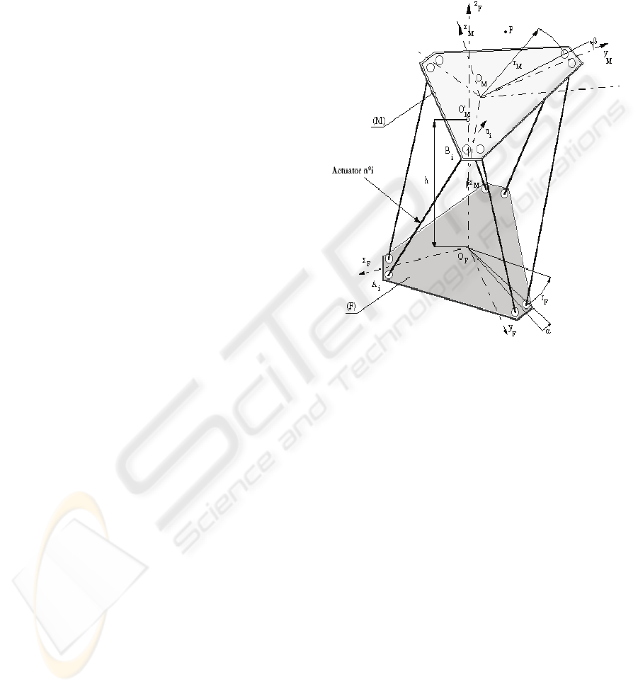
In Figure 2 the geometric parameters, the
corresponding system coordinates and the forces are
represented.
The used notations in the model are:
B
R - radius of fixed base;
B
e ,
B
d - geometric
parameters on the base;
0
21
=λ=λ ;
0
43
120=λ=λ ;
0
65
120−=λ=λ ;
p
r - radius of
the working platform (WP);
p
e
,
p
d
- geometric
parameters on the working platform;
0
21
0=δ=δ ;
0
43
120=δ=δ ;
0
65
120−=δ=δ ;
p
m
- mass of the working platform + the
helicopter;
C = mass centre for the working platform + the
helicopter; C
x’
,C
y’
,C
z’
- main central inertia axes;
I
x’
,I
y’
,I
z’
- main inertia moments; oxyz - coordinate
system of the mobile platform; OXYZ - fixed
reference coordinate system;
iii
ZYXO
′′′
- coordinate
system rotated with the angle
i
λ with respect to the
OXYZ system around the Z axis;
iii
zyxo -
coordinate system rotated with the angle
i
δ
with
respect to the oxyz system around the z axis;
CXY’Z’ - mobile reference system; its axes are
parallel with the fixed coordinate system OXYZ
axes; x
c
, y
c
, z
c
- the coordinates of the mass centre C
with respect to the oxyz system; X
c
, Y
c
, Z
c
= the
coordinates of the mass centre C with respect to the
OXYZ fixed system of the robot.
In the inverse dynamic model, the input data are:
)t(),t(),t(
),t(xz),t(yy),t(xx
CCCCCC
ϕ=ϕθ=θψ=ψ
===
The actuation forces should be computed.
)t(),t(),t(
),t(),t(),t(
665544
332211
τ=ττ=ττ=τ
τ=ττ=ττ=τ
DYNAMIC MODELING OF A 6-DOF PARALLEL STRUCTURE DESTINATED TO HELICOPTER FLIGHT
SIMULATION
221

Figure 2: Dynamic modeling of the parallel robot.
The algorithm for solving the inverse dynamic
model is presented as follows.
6,....,2,1i,e)1(e
B
i
Bi
=−=
(5)
The coordinates of B
i
points with respect to the
iii
ZYXO
′′′
are:
6,...,2,1i,dZ,eY,RX
BBiBiBiBBi
==
′
=
′
=
′
(6)
The coordinates of B
i
points with respect to the
OXYZ are:
6,...,2,1i,
Z
Y
X
100
0CS
0SC
Z
Y
X
Bi
Bi
Bi
ii
ii
Bi
Bi
Bi
=
⎥
⎥
⎥
⎦
⎤
⎢
⎢
⎢
⎣
⎡
′
′
′
⎥
⎥
⎥
⎦
⎤
⎢
⎢
⎢
⎣
⎡
λλ
λ−λ
=
⎥
⎥
⎥
⎦
⎤
⎢
⎢
⎢
⎣
⎡
(7)
6,...,2,1i,e)1(e
p
1i
pi
=−=
−
(8)
6,...,2,1i
,dz,ey,rx
pAipiAipAi
=
−=
′
=
′
=
′
(9)
The coordinates of A
i
points with respect to the
iii
zyxo are:
6,...,2,1i
,
z
y
x
100
0cs
0sc
z
y
x
Ai
Ai
Ai
ii
ii
Ai
Ai
Ai
=
⎥
⎥
⎥
⎦
⎤
⎢
⎢
⎢
⎣
⎡
′
′
′
⎥
⎥
⎥
⎦
⎤
⎢
⎢
⎢
⎣
⎡
δδ
δ−δ
=
⎥
⎥
⎥
⎦
⎤
⎢
⎢
⎢
⎣
⎡
(10)
The coordinates of A
i
points with respect to the
OXYZ are:
6,...,2,1i
,
zz
yy
xx
Z
Y
X
Z
Y
X
CAi
CAi
CAi
321
321
321
C
C
C
Ai
Ai
Ai
=
⎥
⎥
⎥
⎦
⎤
⎢
⎢
⎢
⎣
⎡
−
−
−
⎥
⎥
⎥
⎦
⎤
⎢
⎢
⎢
⎣
⎡
γγγ
βββ
ααα
+
⎥
⎥
⎥
⎦
⎤
⎢
⎢
⎢
⎣
⎡
=
⎥
⎥
⎥
⎦
⎤
⎢
⎢
⎢
⎣
⎡
(11)
Using the relations (7) and (11) the joint
coordinates are:
( )()()
6,...,2,1i
,
BiAiBiAiBiAi
q
ZZYYXX
222
i
=
++=
−−−
(12)
We consider the rotations around the
ZC,YC,XC
′′′
axes (axes parallel with the fix ones
OX, OY, OZ):
A
1
=CθCφ A
2
=-Sφ
A
3
=
0
B
1
= CθSφ B
2
= Cφ
B
3
=
0
C
1
=-Sθ C
2
=0
C
3
=
1
(13)
Then, the angular speed
ω
and the angular
acceleration
ε of the mobile platform may be
determined with the following relations:
⎥
⎥
⎥
⎦
⎤
⎢
⎢
⎢
⎣
⎡
ϕ
θ
ψ
⎥
⎥
⎥
⎦
⎤
⎢
⎢
⎢
⎣
⎡
=
⎥
⎥
⎥
⎦
⎤
⎢
⎢
⎢
⎣
⎡
ω
ω
ω
&
&
&
321
321
321
Z
Y
X
CCC
BBB
AAA
(14)
⎥
⎥
⎥
⎦
⎤
⎢
⎢
⎢
⎣
⎡
ϕ
θ
ψ
⎥
⎥
⎥
⎦
⎤
⎢
⎢
⎢
⎣
⎡
+
+
⎥
⎥
⎥
⎦
⎤
⎢
⎢
⎢
⎣
⎡
ϕ
θ
ψ
⎥
⎥
⎥
⎦
⎤
⎢
⎢
⎢
⎣
⎡
=
⎥
⎥
⎥
⎦
⎤
⎢
⎢
⎢
⎣
⎡
ε
ε
ε
&
&
&
&&&
&&&
&&&
&&
&&
&&
321
321
321
321
321
321
Z
Y
X
CCC
BBB
AAA
CCC
BBB
AAA
(15)
ICINCO 2008 - International Conference on Informatics in Control, Automation and Robotics
222

For the rotations around the fix axes
ZC,YC,XC
′′′
the corresponding cosines may be
determined using the following equations:
θΨ=γθΨ=γθ−=γ
ϕθψ+ϕψ−=βϕθψ+ϕψ−=βϕθ=β
ϕθψ+ϕψ=αϕθψ+ϕψ−=αϕθ=α
cccss
ssccssssccsc
cscsscsssccc
321
321
321
(16)
The inertia moments are:
⎪
⎪
⎪
⎪
⎩
⎪
⎪
⎪
⎪
⎨
⎧
αγ−αγ−αγ−==
γβ−γβ−γβ−==
βα−βα−βα−==
γ+γ+γ=
β+β+β=
α+α+α=
′′′′
′′′′
′′′′
′
′
′
33z22y11xZXXZ
33z22y11xYZZY
33z22y11xXYYX
2
3Z
2
2Y
2
1XZ
2
3Z
2
2Y
2
1XY
2
3Z
2
2Y
2
1XX
IIIII
IIIII
IIIII
IIII
IIII
IIII
(17)
Then, the actuation forces
i
τ are obtained:
()
{}
τ=++
−
g
C
PP
1
T
P
TXCXMI
&&&
(18)
where
⎥
⎥
⎥
⎥
⎥
⎥
⎥
⎥
⎦
⎤
⎢
⎢
⎢
⎢
⎢
⎢
⎢
⎢
⎣
⎡
=
666564636261
565554535251
464544434241
363534333231
262524232221
161514131211
T
P
CCCCCC
CCCCCC
CCCCCC
CCCCCC
CCCCCC
CCCCCC
I
(19)
⎥
⎥
⎥
⎥
⎥
⎥
⎥
⎥
⎦
⎤
⎢
⎢
⎢
⎢
⎢
⎢
⎢
⎢
⎣
⎡
=
333231
232221
131211
p
p
p
aaa000
aaa000
aaa000
000m00
0000m0
00000m
M
(20)
⎥
⎥
⎥
⎥
⎥
⎥
⎥
⎥
⎦
⎤
⎢
⎢
⎢
⎢
⎢
⎢
⎢
⎢
⎣
⎡
ϕ
θ
Ψ
=
&&
&&
&&
&&
&&
&&
&&
C
C
C
p
Z
Y
X
X
⎥
⎥
⎥
⎥
⎥
⎥
⎥
⎥
⎦
⎤
⎢
⎢
⎢
⎢
⎢
⎢
⎢
⎢
⎣
⎡
=
333231
232221
131211
bbb000
bbb000
bbb000
000000
000000
000000
C
(21)
⎥
⎥
⎥
⎥
⎥
⎥
⎥
⎥
⎦
⎤
⎢
⎢
⎢
⎢
⎢
⎢
⎢
⎢
⎣
⎡
ϕ
θ
Ψ
=
&
&
&
&
&
&
&
C
C
C
P
Z
Y
X
X
⎥
⎥
⎥
⎥
⎥
⎥
⎥
⎥
⎦
⎤
⎢
⎢
⎢
⎢
⎢
⎢
⎢
⎢
⎣
⎡
−
=
0
0
0
gm
0
0
T
p
C
g
⎥
⎥
⎥
⎥
⎥
⎥
⎥
⎥
⎦
⎤
⎢
⎢
⎢
⎢
⎢
⎢
⎢
⎢
⎣
⎡
τ
τ
τ
τ
τ
τ
=τ
6
5
4
3
2
1
(22)
In (19)-(21):
3311
aa ,,L depend on the
platform inertia moments
XZZYYXZYX
IIIII,I
′′′′′′′′′
and
3..1iC,B,A
iii
= ;
3311
b,,b L depend on the
platform inertia moments
XZZYYXZYX
IIIII,I
′′′′′′′′′
and
3..1iC,B,A
iii
=
&
&
&
;
6611
C,,C L depend on the
direction cosines for the platform, the coordinates of
points
6..1iA
i
= and the coordinates of the platform
mass center
6..1iC
i
= .
4 SIMULATION TESTS
The achieved kinematic and dynamic algorithms
have been implemented in the developed simulation
system (Pisla, 2005), (Pisla, 2007). It consists of five
main modules: Kinematics; Singularities;
Workspace; Trajectory, Dynamics. Within the
simulation system the virtual graphical model was
created, the 3D functional model allows the designer
to understand its functionality (Figure 3).
The geometric parameters can be modified
within the 3D modeling software influencing the
simulation environment. The assembly relations
between the parts, subassemblies and between parts
and subassemblies can be also modified. These
facilities enable the possibility to develop complex
relations between the shape of the workspace, links
and geometrical dimensions in order to optimize the
parallel structure.
The parallel structure parameterization enables
the development of the geometric optimization and
the robot workspace shape. The obtained results are
useful for the designers in understanding the
workspaces characteristics distribution and parallel
robots optimization.
Figure 3: Simulation program for a 6-DOF parallel
structure.
DYNAMIC MODELING OF A 6-DOF PARALLEL STRUCTURE DESTINATED TO HELICOPTER FLIGHT
SIMULATION
223

The presented simulation system enables the
motion visualization in a modular manner valid for
virtually any structure of parallel robot, introducing
the kinematic and dynamic models over the virtual
robot. The introduction of extra conditions related to
any component is possible with a relative small
number of actions. By using the graphical interface
presented in Figure 3, the facilities of the simulation
software enable to develop a complex study about
the robot kinematics and dynamics in order to
optimize the parallel structure.
5 CONCLUSIONS
In this paper a solution for solving of the inverse
dynamics for a 6-DOF parallel robot conceived for a
helicopter simulator has been presented. The
dynamic model derived through virtual work
principle has a compact form and offer the
possibility of a more complex dynamic study in
order to evaluate their dynamic capabilities and to
generate innovative control algorithms.
ACKNOWLEDGEMENTS
This research was financed from the research grants
awarded by the Romanian Ministry of Education
Research and Youth.
REFERENCES
Pierrot, F., M. Uchijama, , P. Dauchez, Fournier, A., 1990,
A New Design of a 6-DOF Parallel Robot, Journal of
Robotics and Mechatronics, 2: 92-99.
Codourey. A., 1991. Contribution a la Commande des
Robots Rapides et Precis. Application au robot
DELTA a Entrainement Direct. These a l’Ecole
Polytechnique Federale de Lausanne.
Guglielmetti, P. and Longchamp, R., 1994. A Closed
Form Inverse Dynamics Model of the DELTA Parallel
Robot. In the Symposium on Robot Control, pages 51-
56, Capri, Italia.
Stamper, R. and Tsai, L.W., 1998. Dynamic Modeling of a
Parallel Manipulator with Three Translational Degrees
of Freedom. DETC98/MECH-5956, in ASME Design
Engineering Technical Conference, Atlanta, GA.
Honneger, M. Codourey, A. and Burdet, 1997. E.
Adaptive control of the Hexaglide, a six d.o.f. parallel
manipulator. In IEEE Int. Conf. On Robotics and
Automation, pages 543-548, Albuquerque.
Tsai, L.-W., 1999. Robot Analysis, the Mechanics of
Serial and Parallel Manipulators, Wiley.
Guégan, S. and Khalil. W., 2002. Dynamic Modeling of
the Orthoglide. Advances in Robot Kinematics
(J.Lenarcic and F. Thomas, Ed.). Kluver Academic,
Publication, Netherlands, 387-396.
Geng Z..and Haynes, L.S., 1992. On the dynamic model
and kinematic analysis of a class of Stewart platforms.
Robotics and Autonomous Systems, 9:237-254.
Liu, K., 1993. The singularities and dynamics of a Stewart
platform manipulator. Journal of Intelligent and
Robotic Systems, 287-308.
Miller, K. and Clavel. R., 1992. The Lagrange-Based
Model of DELTA-4 Robot Dynamics. Robotersysteme,
8:49-54.
Merlet. J.-P., 2000. Parallel robots. Kluver Academic
Publisher.
Pisla, D., Kerle, H., 2000. Development of Dynamic
Models for Parallel Robots with Equivalent Lumped
Masses. In 6th International Conference on Methods
and Models in Automation and Robotics, , pages 637-
642, Międzydroje, Poland.
Itul, T. and Pisla, D., 2003. Comparative Study between
D’Alembert Principle and Lagrange Formulation for
Guiding in three Points Parallel Robot Dynamic
Analysis. In 14th International Conference on Control
Systems and Computer Science, Politehnica Press,
Bucharest, 1:100-105.
Itul, T., Pisla, D. and Pisla, A., 2006.
On the Solution of
Inverse Dynamics for 6-DOF Robot with Triangular
Platform, in 1st European Conference on Mechanism
Science, E
UCOMES, ISBN 3-901249-85-0 (on CD),
Obergurgl, Austria, February 21–26.
Kovecses, J., Piedboeuf and J.C., Lange, C., 2002.
Methods for Dynamic Models of Parallel Robots and
Mechanisms, in the Workshop on Fundamental Issues
and Future Research Directions for Parallel
Mechanisms and Manipulators, pages 339-347,
Quebec.
Reid L.D., Nahon M.A., 1988. Response of Airline Pilots
to Variations in Flight Simulator Motion Algorithms,
Vol. 25, No. 7, 639-646.
Nahon M.A., Gosseli, 2000. A comparison of flight
simulator motion – base architectures, Journal of
Mechanical Design, Volume 122.
Andreev A. N., Danilov A. M.. Information models for
designing, conceptual broad-profile flight simulators,
Measurement Techniques, Vol 43, No. 8.
Plitea, N., Hesselbach, J., Pisla, D., Raatz, A., Vaida, C.,
Wrege, J., Burisch, A., 2006. Innovative Development
Of Parallel Robots And Microrobots, Acta Tehnica
Napocensis, Series of Applied Mathematics and
Mecanics, no. 49, vol. 5, pp. 15-26.
Pisla, A., Plitea, N., Prodan, B., 2007. Modeling and
simulation of parallel structures used as flight
simulators, in Proc of TMT2007, Tunisia.
Pernkopf, F., Husty, M.L., 2002. Singularity analysis of
spatial Stewart-Gough platforms with planar base and
platform, In Proc. ASME Design Eng. Tech. Conf.
Montreal, Canada, September 30 October 2.
Pisla, D. L, 2005. Modelarea cinematica si dinamica a
robotilor paraleli, Editura Dacia Cluj-Napoca.
ICINCO 2008 - International Conference on Informatics in Control, Automation and Robotics
224
