
A UML Profile for Enterprise Ontology
José Cordeiro
1
, Joaquim Filipe
1
and Kecheng Liu
2
1
EST Setúbal/IPS, Rua do Vale de Chaves, Estefanilha
2910-761 Setúbal, Portugal
j.cordeiro@computer.org, j.filipe@est.ips.pt
2
The University of Reading, Whiteknights, Reading, RG6 6AF, U.K.
k.liu@reading.ac.uk
Abstract. Enterprise Ontology (EO) is a new subject that applies the Ψ-theory
to the development and conception of social information systems. This theory,
proposed by Jan Dietz, is based on the Language Action Perspective. In order
to model an enterprise this theory presents a modelling method composed by
four distinct aspect models, which use a collection of tables and diagrams to
express themselves. A domain specific language was supplied for those dia-
grams that it is not standard or easily portable. In order to make these diagrams
more useful and available this paper proposes the use of the Unified Modelling
Language (UML) to represent EO most important diagrams where the EO main
concepts are shown. The use of UML will bring some important benefits such
as portability, interoperability, wider audience and understanding among oth-
ers. In this sense a UML 2 profile has been created for representing the dia-
grams mentioned. An example of application of this profile is shown and an ex-
tended discussion of its creation is made. This will address the difficulties and
issues found when metamodelling the solution using UML and will help to as-
sess the feasibility of UML for this kind of problems.
1 Introduction
The Ψ-theory proposed by Jan Dietz [2] provides the foundations for designing and
engineering of enterprises seen as social information systems. This theory captures
the stable essence of any organization by focusing on commitments and the way peo-
ple interact using language. This focus on language rather than material actions or
technology comes from the Language Action Perspective view of the world (see, for
example, [14]) in which it is based. The Ψ-theory comprises a modelling method
composed by four distinct aspect models: the construction model, the process model,
the action model and the state model. A methodology named “Design and Engineer-
ing Methodology for Organizations” (DEMO) is the basis for this modelling method
[2], [3]. As many modelling methods, a few diagrams are used as a way of expres-
sion. Because these diagrams constitute the main communicational mean for repre-
senting the structure of the enterprise according to the Ψ-theory we are interested in
include these diagrams together with other diagrams in information system develop-
ment projects. This is not easy due to the proprietary language used by these diagrams
and its lack of interoperability with other modelling languages. Also a formal verifi-
Cordeiro J., Filipe J. and Liu K.
A UML Profile for Enterprise Ontology.
DOI: 10.5220/0004464500070020
In Proceedings of the 2nd International Workshop on Enterprise Systems and Technology (I-WEST 2008), pages 7-20
ISBN: 978-989-8111-50-0
Copyright
c
2008 by SCITEPRESS – Science and Technology Publications, Lda. All rights reserved

cation is not automatically made and there are only a small number of tools to work
with those diagrams. To overcome these problems we propose to use the Unified
Modelling Language (UML), to express the most important diagrams of those mod-
els. UML is today a de facto standard widely used for modelling purposes, having
numerous tools available and its use will bring us some important benefits such as:
A wider audience will be able to use and understand the diagrams.
• Diagram interoperability and inclusion in software projects
• Formal representation and automatic verification of the diagrams
In this sense this paper presents and proposes a new UML 2 profile for representing
those different types of diagrams. The difficulties and issues raised in the profile
creation will also be the focus of this work because they will show the feasibility and
the problems of using UML for such purposes.
This paper is organised as follows: section 2 presents related work, section 3 summa-
rizes the main concepts of Enterprise Ontology (EO), the proposed UML Enterprise
Ontology profile will be shown and exemplified in section 4, section 5 will present
issues and rationale related to the EO profile development and finally, conclusions
will be given in section 6.
2 Related Work
We found just a small number of papers that refer to the use of UML with DEMO. In
[13], Shishkov and Dietz suggest using DEMO to derive UML use cases. In this work
a mapping from DEMO Business Transactions to UML Use Cases is proposed. In
fact there is a general tendency to separate the use of DEMO and UML. For example,
in [7] DEMO is used to model the business processes prior to information systems
modelling using UML. Nevertheless, the most significant work relating UML and
DEMO is [11]. In this paper instead of a direct UML representation it is proposed a
language mapping between DEMO models and UML. This mapping is accomplished
in three phases: first a concept mapping between both languages is made, next a nota-
tional mapping is performed and at last there is a diagram transformation. In fact, a
similar approach is taken when we create the UML profiles as we will see. In UML
profiles concept matching is used to find the appropriate metaclasses corresponding
to the DEMO model elements, also a notational option is taken for the created stereo-
types and finally some new diagrams are created for showing the new model ele-
ments. Even so according to this paper it will be necessary to have the original
DEMO diagrams instead of a direct UML representation as we pretend.
Regarding UML profiles much work has been done and some references will be
pointed afterwards when appropriate.
3 Enterprise Ontology
Enterprise Ontology (EO) captures the essential aspects of any organization by focus-
ing on the ontological level of business where people interact, commit themselves and
8
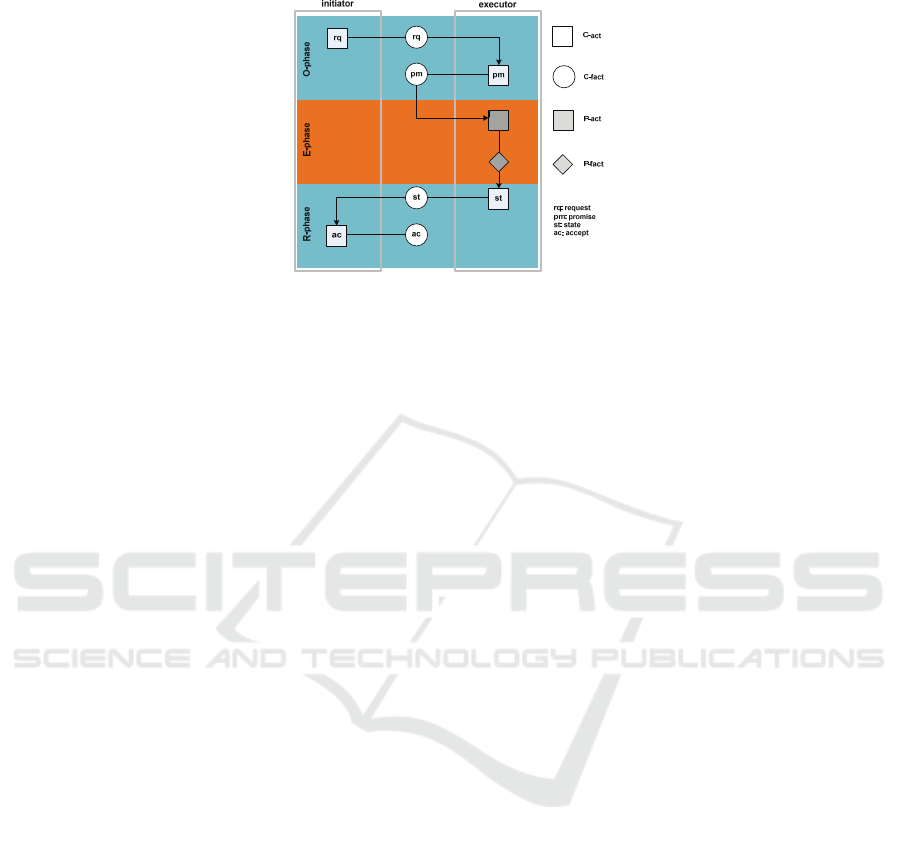
Fig. 1. The Basic Transaction Pattern (adapted from [3]).
produce results. At this level people use language acts as the driver of any business
transaction or coordination acts. EO is about the construction and operation of an
organization. The Ψ-theory establishes the basis and the theoretical support for EO.
The Ψ-theory is composed by four axioms and one theorem. The first axiom – the
Operation Axiom – presents an organization as a group of actors performing two
kinds of acts: coordination acts (C-acts) and production acts (P-acts). C-acts are lan-
guage acts used by actors to engage themselves in commitments and to ultimately
originate the P-acts responsible for producing the effective work. The result of per-
forming a C-act is a coordination fact (C-fact), whereas the result of performing a P-
act is a production fact (P-fact) or production result. The second axiom – the Transac-
tion Axiom – comes from the observation that P-acts and C-acts seems to occur in a
universal pattern called transaction. This transaction is a key concept of the Ψ-theory
and EO. The complete transaction pattern is seen as a socionomic law that underlies
the conducting of any business always and everywhere. This transaction has its roots
in the notion of conversation for action [14] and the Workflow Loop [8] both from
the Language Action Perspective. In fig. 1 we depict the basic transaction pattern
which has three phases: an order phase where the negotiation about the P-act to be
executed takes place. In this phase two types of C-acts are usually performed: a re-
quest by the initiator actor and a promise to accomplish it by the executor actor. The
next phase is the execution phase where the P-act is actually performed. Finally, the
result phase ends the transaction with the performance of a C-act stating the comple-
tion of execution of the P-act by the executor actor and a C-act by the initiator actor
accepting the result. The third axiom – the Composition Axiom – is concerned with
the interrelation of P-facts in a production world (the P-world). In particular the en-
closing relationship between transactions is analysed. Finally, the fourth axiom – the
Distinction Axiom – is about the human abilities that have a significant role in per-
forming C-acts namely the performa, informa and forma abilities. The performa abil-
ity is considered the essential human ability for doing business and is part of the onto-
logical level of EO. The Organization Theorem completes the Ψ-theory by stating
that “the organization of an enterprise is a heterogeneous system that is constituted as
the layered integration of three homogeneous systems: the B-organization (from busi-
ness), the I-organization (from intellect), and the D-organization (from Document)”
[2, p.115].
9
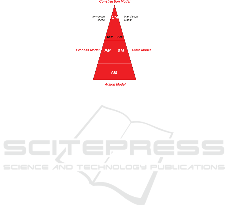
Fig. 2. The four DEMO aspect models (adapted from [2]).
For designing and engineering organizations EO is supported by the DEMO meth-
odology. The DEMO methodology defines the required steps for that purpose and
uses a modelling method composed by four distinct aspect models: the construction
model, the process model, the action model and the state model that together consti-
tutes the complete ontological knowledge of an organization (fig. 2). The construc-
tion model (CM) specifies transactions types, associated actors roles and information
banks (conceptual stores of C-facts or P-facts). The CM is divided in two similar
models: the interaction model (IAM) and the interstiction model (ISM) that shows us
respectively the active and the passive influences between actor roles. The process
model (PM) details the CM by showing the specific transaction patterns for each
transaction type in the CM. The action model (AM) is the most detailed level and it
specifies the action rules that serve as guidelines for the actors. The last model, the
state model (SM) specifies the state space of the P-world. It includes object classes,
fact types, result types and ontological coexistence rules. In general these models are
expressed by different diagrams and tables. Table 1 show us the different diagrams
and tables used by each of them and what they depict. As it is shown the AM doesn’t
use any diagram and the SM uses a very specific type of diagram that doesn’t pre-
sents directly the main concepts of EO, namely the transaction types, and we decided
not to represent them using UML. Thus, in this work we will be interested in provide
UML diagrams to mirror the following diagrams: ATD, PSD and ABD.
4 The Enterprise Ontology Profile
In figure 3 a part of the metamodel for the UML Profile created for EO is presented.
In this metamodel it is shown the equivalent UML elements for the DEMO Actor
Transaction Diagram (ATD) elements. The corresponding stereotypes and constraints
for this profile are detailed in table 2. Discussion of the creation of the complete pro-
file is made in the next section.
10

Table 1. DEMO aspect models.
Model Expressed by Typical contents
Interaction
Actor Transaction Diagram (ATD)
Actor roles, transaction types and
their connecting links
Transactions Result Table (TRT) Transaction and result types
Process
Process Structure Diagram (PSD)
C-act/C-result, P-act/P-result, causal
and conditional links and responsibil-
ity areas of actor roles
Information Use Table (IUT)
Process steps and object class, fact
types or result types
Action Action Rule Specifications (ARS) Action rules
State
Object Fact Diagram (OFD)
Object classes, fact types, result
types and existential laws
Object Property List (OPL) Property types, object classes, scales
Interstriction
Actor Bank Diagram (ABD)
Information banks, actor roles and
information links
Bank Contents Table (BCT)
Object classes, fact types, result
types and production banks
Table 2. EO stereotype definitions part 1 – ATD elements.
Name TransactionType
Extended Class Class Notation
Description Represents the transaction type concept.
Constraints ------
Notes The name of the transaction should be a capital T
followed by the transaction number (ex: T02 )
Name Actor Role
Extended Class Class
Description Represents the elementary actor role concept.
Constraints ------
Notes No special notation. Usually it is shown as a rectangle with the actor role name
inside. The actor role name should be a capital A followed by the actor role
number (ex. A02)
Name CompositeActorRole
Base Class ActorRole Notation
Description Represents the composite actor role concept.
As a class but filled
using a gray colour
Constraints ------
Notes The actor role name should be the capitals CA followed
by the actor role number (ex. CA03)
Name ActorRoleLink
Extended Class Association
Description A relationship between an actor role and a transaction type
Constraints 1) It is a binary association
2) Must connect a TransactionType and an ActorRole element
3) It is an abstract metaclasse
Name InitiatorLink
Base Class Actor RoleLink
Description A special kind of an ActorRoleLink that connects an ActorRole and a
TransactionType where the ActorRole plays the role of the initiator of the
transaction
Constraints ------
Notes Usually no adornments are shown.
There is an implicit navigation from the actor role to the transaction.
11
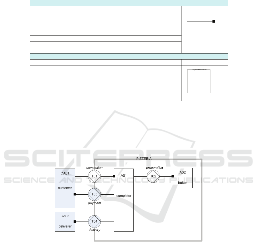
Table 2. EO stereotype definitions part 1 – ATD elements(cont).
Name ExecutorLink
Base Class Actor RoleLink Notation
Description A special kind of an ActorRoleLink that connects
an ActorRole and a TransactionType where the
ActorRole plays the role of the executor of the
transaction
The line end with
the black square
must be connected
to the actor role
Constrains ------
Notes There is an implicit navigation from the
transaction to the actor role.
Name Organization
Extended Class Package Notation
Description Represents a group of actor roles and transaction
types which belong and take place inside an
organization
Constrains ------
Notes The name of the package is placed upon its upper
boundary line
A special UML diagram – the AT diagram – one of diagrams which we
propose for this profile is a special case of a UML Class diagram. This dia-
gram is used for showing actor roles and transaction types and the links be-
tween them and mimics the original DEMO ATD. In figure 4 an example of
an ATD is given and in figure 5 the same diagram is reproduced with the EO
profile applied to it.
Fig. 3. Example of the DEMO ATD of a pizzeria (adapted from [2]).
12
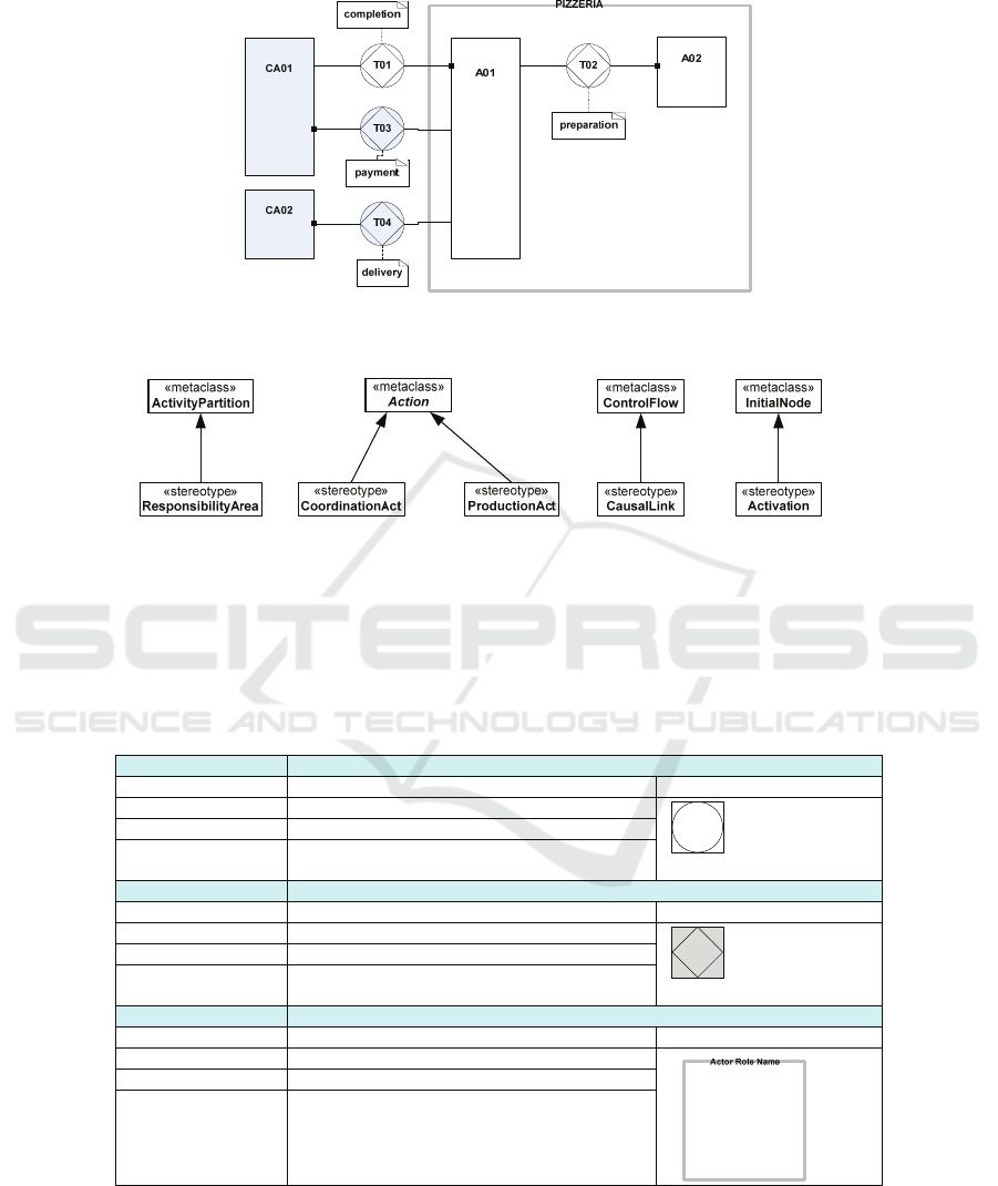
Fig. 4. An UML AT Diagram applied to the pizzeria example using the EO Profile.
Fig. 5. EO profile metamodel part 2 - UML representation of PSD elements.
In figure 6 it is shown the second part of the EO profile which includes
the equivalent UML elements for the DEMO Process Structure Diagram
(PSD) elements. The corresponding stereotypes and constraints for this profile
are detailed in table 3.
Table 3. EO Profile stereotype definitions part 2 – PSD elements.
Name CoordinationAct
Extended Class Action Notation
Description Represents the C-act concept.
Constraints ------
Notes Just one symbol meaning the combination of a C-
act with a C-result
Name ProductionAct
Extended Class Action Notation
Description Represents the P-act concept.
Constraints ------
Notes Just one symbol meaning the combination of a P-
act with a P-result
Name ResponsibilityArea
Extended Class ActivityPartition Notation
Description Represents the responsibility area concept
Constraints isDimension = true
Notes It will not be possible to have nesting of actor
roles because each actor role establishes a unique
dimension.
13
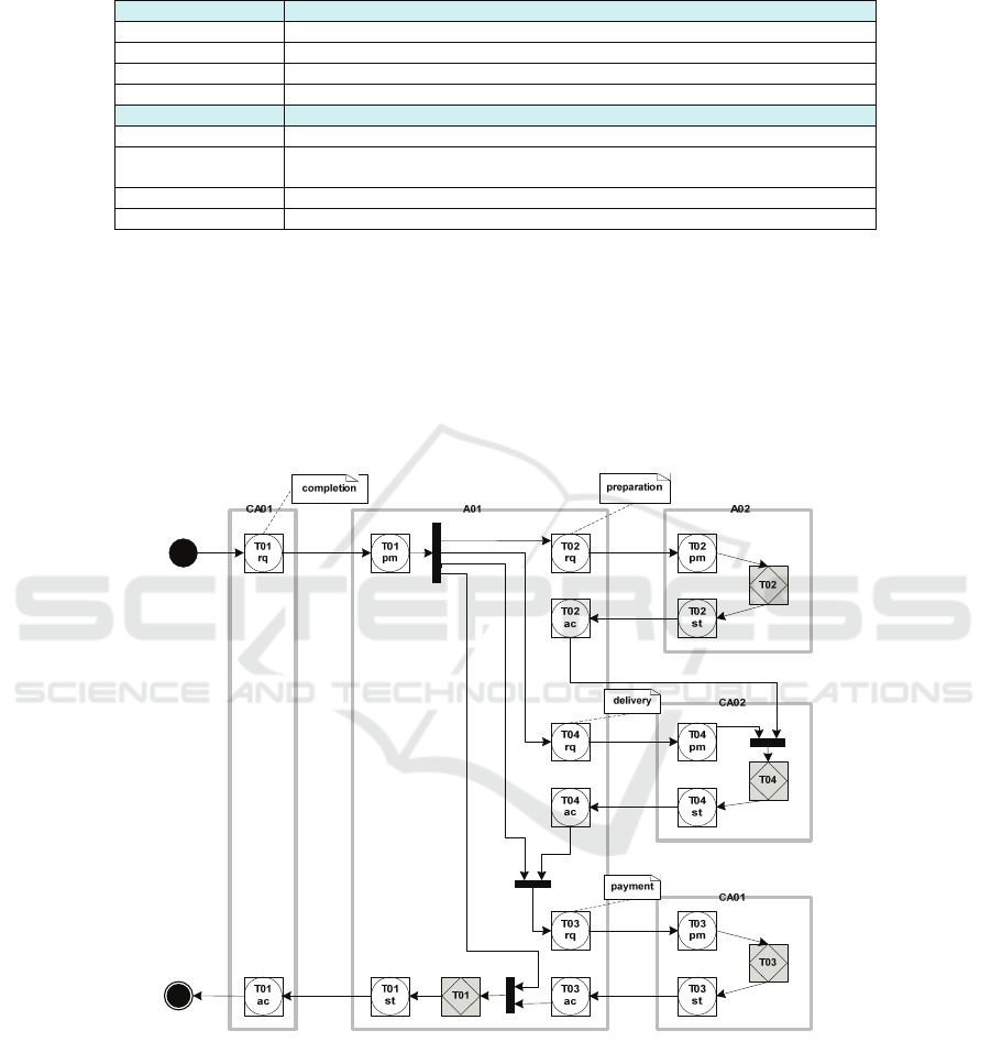
Table 3. EO Profile stereotype definitions part 2 – PSD elements(cont).
Name CausalLink
Extended Class ControlFlow
Description A link used to show the control flow between C-act and P-acts.
Constraints ------
Notes It is equivalent of the causal link
Name Activation
Extended Class InitialNode
Description It represents the start of a process. It can be placed inside a Responsibility Area
meaning self activation or outside meaning external activation.
Constraints ------
Notes
As in the case of the AT Diagram a new UML diagram – the Process Structure
Diagram - was created to show DEMO PSD using UML. This diagram is a special
case of a UML Activity Diagram. Unfortunately UML diagrams are not part of the
main specification of UML, they are not model elements, therefore we have to intro-
duce these diagrams informally and it will not be possible to formalize some aspects
of the diagrams, for example positioning rules for the included elements. An example
of a PSD is given in figure 7. In figure 8 it is shown a UML PS diagram with the EO
Profile applied.
Fig. 6. An UML PS Diagram applied to the pizzeria example using the EO Profile.
Figure 9 shows the third and last part of the EO profile which includes the equiva-
lent UML elements for the DEMO Actor Bank Diagram (ABD) elements. The cor-
responding stereotypes and constraints for this profile are detailed in table 4. Also a
14
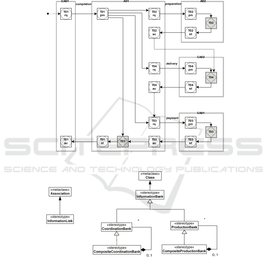
new UML diagram – the Actor Bank Diagram - is proposed for representing the
DEMO ABD. This diagram is also a special case of a UML Class Diagram. This
diagram is very similar to the ATD.
Fig. 7. Example of the DEMO PSD of a pizzeria (adapted from [2]).
Fig. 8. EO profile metamodel part 3 - UML representation of ABD elements.
15

Table 4. EO Profile stereotype definitions part 3 – ABD elements.
Name InformationBank
Extended Class Class
Description A production or a coordination bank.
Constraints ------
Notes
Name CoordinationBank
Base Class InformationBank Notation
Description Represents a coordination bank
Constraints ------
Notes The coordination bank name should be the capitals CB
followed by the bank number (ex. CB02)
Name CompositeCoordinationBank
Base Class CoordinationBank Notation
Description Represents a composite coordination bank
Constraints ------
Notes The composite coordination bank name should be the
capitals CCB followed by the bank number (ex. CCB02)
Name ProductionBank
Base Class InformationBank Notation
Description Represents a production bank
Constraints ------
Notes The production bank name should be the capitals PB
followed by the bank number (ex. PB03)
Name CompositeProductionBank
Base Class ProductionBank Notation
Description Represents a composite production bank
Constraints ------
Notes The composite production bank name should be the capitals
CPB followed by the bank number (ex. CPB04)
Name InformationLink
Extended Class Association Notation
Description A connection relating actor roles and information banks
Constraints 1) It is a binary association
2) Must connect an InformationBank and an ActorRole
Notes
5 EO Profile Creation
If we want to have the benefits of using UML tools such as model interchange, model
validation and model storage it is necessary to create UML Profiles instead of a com-
plete metamodel for representing the DEMO diagrams. Thus, and in order to build
these profiles we should follow some guidelines (see for example [4]). In a general
and simple view these guidelines recommend to create first a domain metamodel, to
choose from this metamodel the relevant elements, to extend the appropriate UML
metamodel elements with some of those elements and to define additional constraints
and tagged values (see [12]). In our case we found as not necessary to create the do-
main metamodel because we already have the domain elements which correspond to
the DEMO diagram elements. In spite of skipping this step and although simple the
remaining process it has many issues, difficulties and compromises specially because
we are metamodeling non object-oriented theories. In the next sections some of the
issues and problems found for each DEMO diagram will be reported. It should be
16

also noted that the EO UML profile that was created uses version 2.1.2 of the UML
superstructure and infrastructure specifications [9], [10].
5.1 Development Issues - AT Diagram
The ATD diagram shows mainly actor roles, transaction types and links connecting
them. For transaction types we don’t have any similar UML model element and in
this situation it is usual to extend the metaclass ‘class’ as a representation of a con-
cept. Thus, the initiator or executor links between transaction types and actor roles
should be expressed using the association metaclass. This is the most powerful rela-
tionship between model elements that is used to connect classifiers. The problem is
the representation of actor roles. In UML we have an actor element that matches the
concept of an actor role, it is a classifier and support associations as well but this
element has limited capabilities compared to classes. So, the best solution was to
express actor roles using classes as well. This will allow a more powerful expression
of actor roles, it will permit to create composite actor roles based on elementary actor
roles using the inheritance and composition concepts of object-orientation and it will
have some extra benefits when creating the EO profile elements for the PSD DEMO
diagram. The last ATD element that we need to represent is the boundary of an or-
ganization. This is a grouping element that joins transactions, actor roles and links
belonging to an organization, but some transactions with external actor roles are not
placed completely inside the organization boundary but are seen as belonging to the
boundary itself. This cannot be represented used the common UML grouping ele-
ment, the package. Elements of a package belong to the package and not to its boun-
dary. Other UML grouping elements such as the activity partition or the subject (of a
use case) are not suited for this purpose, they can only surround very specific UML
model elements and the related concepts don’t match with our goals. So, we adopted
as a solution to use the package extension but to limit the elements of the organization
package for being transaction types where all the actors are organizational actor roles
and all the actor roles belong to the organization. A possibility is to show the boun-
dary transaction types using a second package which includes only boundary transac-
tions.
Regarding the notation we choose to make the UML Profile elements close to the
original notation used in the DEMO diagrams. UML allows some flexibility in the
notation and this possibility to make it close to the original or to the traditional UML
as identified in [1] is used by our solution.
5.2 Development Issues - PS Diagram
The DEMO PSD shows two combined symbols for correspondingly C-acts/C-results
and P-acts/P-results. The links between these symbols are made using causal and
conditional links. Also external and self-activation lines are used to represent the start
of the depicted processes. A last element in these diagrams is a grouping element
defining the responsibility area of an actor role. Giving the “business process” nature
of these kinds of diagrams it would be most useful to represent them using an UML
17

activity like diagram. For this purpose their elements should be equivalent to the
typical UML activity elements. In fact this is possible because the main elements, C-
acts/C-results and P-acts/P-results, can be represented by extending the UML action
element. If we consider just the C-acts and P-acts, they are both some kind of action
and they are suited to be represented as actions. We should make implicit the pro-
duced C-results and P-results; it will be possible to see them as the output of the cor-
responding actions. Regarding the notation we will make it close to the original PSD
elements. We choose to represent C-acts and P-acts using the combined symbol and
thus making explicit the associated C-results and P-results. The C-act/C-result symbol
is depicted as a single UML element hiding the combined nature of the symbol. This
symbol results from joining a circle – a C-fact (or C-result) type - and a square – a C-
act type - but this combination cannot be made using UML. There is no possibility to
combine two different UML elements without creating a new element with no con-
nection to the original symbols. The same applies to the P-act/P-result symbol which
uses a square for the P-act and a diamond for the P-fact (or P-result) type that it is
represented as a single symbol. UML doesn’t allow us to combine model elements
but we took advantage of the flexibility in the notation. Regarding the causal link it is
in fact a kind of a UML control flow causing the flow to jump from one act to the
next. In the case of the conditional link there is no equivalent UML element but we
can use some of the UML elements to produce the same effect as the conditional link.
In the case of the conditional link appear at the end of a conditional branch it can be
replaced by a decision node at the beginning of the branch and a merge node at the
end. In case of appearing at the end of a concurrent branch it can be replaced by a
fork at the beginning and a join at the end. This last case is illustrated in fig. 8. In the
PSD also responsibility areas are used to delimit a group of acts performed by an
actor role. In this case an extension of activity partition is suited for this goal and can
play the same role. This solution is optimal because we choose before to use UML
extended class elements for actor roles. Thus, actor roles will be the responsible
agents for the corresponding C-acts or P-acts. At last for activation lines UML also
provide model elements, we can use the Initial node of the activity diagram connected
to a C-act using a control flow to express the starting point of a process. If this Initial
node lies inside a responsibility area where it is connected to a C-act it means a self
activation, otherwise if it lies outside the responsibility area it means an external acti-
vation. Just a final remark to point the necessity of including a final flow node to
indicate the end of a process. There is no similar model element in the original PSD.
5.3 Development Issues - AB Diagram
The last part of the UML profile concerns the creation of the corresponding UML
elements for the DEMO ABD. This diagram is similar to the PSD and it can use most
of the elements defined before. We just need to express as well elementary and com-
posite production and coordination banks and information links. These banks are just
a kind of databases and can be shown using an extension of the UML class. Also we
can use the object oriented mechanisms to differentiate from elementary and compo-
site production and coordination banks. The ABD uses also a combined symbol for a
production and coordination bank that refers to an information bank. An information
18

as a general kind of bank can be expressed as a base class and we can use inheritance
to derive the production and coordination banks. We lose the combined nature but we
gain in expressivity. Finally the information link is naturally expressed as an exten-
sion of an association because it relates stereotypes of classes.
Table 5. Summary of identified UML issues.
UML issue Comments
A
diagram is not an
UML metamodel
element
It is not possible to adequately formalize relationships between dia-
grams and model elements because the diagrams are not UML ele-
ments
UML metamodel
grouping elements with
limited options
The most important grouping UML element - the package – provides
a special kind of grouping that doesn’t allow representing elements
that belong to two packages simultaneously; this is the case of
boundary elements such as some of the transaction types in AT
diagrams. Other UML grouping elements such as the Activity
Partition and the Subject have limited application given the
restrictions in the elements they may contain.
UML metamodel ele-
ments usually have
hidden aspects
Some simple UML elements cannot be used to represent similar
concepts because they cannot be freely associated with other ele-
ments. This is hidden and it is a consequence of the rigidity of the
UML metamodel when defining these elements. In the case of the
actor element its limited capabilities make it preferable to use classes
to represent actor roles although an actor was a better matching con-
cept.
UML metamodel
elements without
combinations among
them
It is not possible to combine different UML elements in one joint
element preserving the original meaning of the individual elements.
The example was the C-act/C-result and the production
bank/coordination bank elements which had unique symbols for the
combined element.
6 Conclusions and Future Work
In this paper a UML profile for Enterprise Ontology was introduced. This profile
brings important benefits for the underlying DEMO methodology such as:
• Possibility to communicate the diagrams to information system and soft-
ware development teams and to include them with other diagrams in the
same projects
• Interoperability of the diagrams with other model tools
• Consistency, verifiability and formalization of the diagrams
Concerning the profile creation this paper has raised some issues that are resumed in
table 5. It should be noted as well that the stereotypes created in this profile intro-
duced a reduced number of constraints in order to have enough freedom when using
UML. Some additional constraints can be added if there is the necessity of a more
formal and rigid expression of the produced diagrams.
This work is part of a research project that has as a goal to create a unified and
fundamental theory for software development that integrates some relevant concepts
of three different socio-technical theories, namely Organizational Semiotics [6], the
19

Theory of Organized Activity [5] and the Language Action Perspective represented in
this paper by the Ψ-theory and the DEMO methodology. Concerning the UML profile
development issues raised in this paper, they complement another group of issues
identified in [1]. As a future work a UML profile of the new theory will be proposed
that will share some of the elements and concepts presented in this paper and in [1].
References
1. Cordeiro, J., Liu, K.: UML 2 Profiles for Ontology Charts and Diplans - Issues on Meta-
modelling. Proc. of EMISA 2007: 191-204, (2007).
2. Dietz, J. L.: Enterprise Ontology – Understanding the Essence of Organizational Operation.
In: Enterprise Information Systems VII. Eds. C. Chen, J. Filipe, I. Seruca, and J. Cordeiro.
Springer, Dordrecht, The Netherlands (2006)
3. Dietz, J. L.: The deep structure of business processes. Communications of the ACM 49, 5,
58-64. (May 2006)
4. Fuentes, L. and Vallecillo, A.: An Introduction to UML Profiles. UPGRADE, The Euro-
pean Journal for the Informatics Professional, 5(2):5-13 (2004). ISSN: 1684-5285.
5. Holt, A.: Organized Activity and Its Support by Computer, Kluwer Academic Publishers,
Dordrecht, The Netherlands (1997).
6. Liu, K.: Semiotics in Information Systems Engineering, Cambridge University Press,
Cambridge, UK (2000).
7. Mallens, P., Dietz, J., and Hommes, B-J.: The Value of Business Process modelling with
DEMO Prior to Information Systems modelling with UML. In Proc. EMMSAD’01, Inter-
laken, Switzerland (2001).
8. Medina-Mora, R., Winograd, T., Flores, R., Flores, F. The Action Workflow approach to
workflow management technology. In J. Turner and R. Kraut, Eds., Proceedings of the 4th
Conference on Computer Supported Cooperative Work. ACM, New York (1992).
9. OMG: Unified Modeling Language Superstructure Specificacion, v2.1.2. Available:
http://www.omg.org/spec/UML/2.1.2/Infrastructure/PDF/ (Apr 2008)
10. OMG: Unified Modeling Language Infrastructure Specificacion, v2.1.2. Available: http://
www.omg.org/spec/UML/2.1.2/Superstructure/PDF/ (Apr 2008)
11. Rittgen, P.: A language-mapping approach to action-oriented development of information
systems. Eur. J. Inf. Syst. 15, 1, 70-81. (Feb. 2006)
12. Rumbaugh, J., Jacobson, I. and Booch, G.: The Unified Modeling Language Reference
Manual (2nd edition), Addison-Wesley, Reading, MA (2005)
13. Shishkov, B. and Dietz, J.: Deriving Use cases from Business processes, the Advantages of
DEMO. In: Enterprise Information Systems V. Eds. O. Camp, J.B.L. Filipe, S. Hammoudi,
and M. Piattini. Kluwer Academic Publishers, Dordrecht/Boston/London (2004)
14. Winograd, T. and Flores, F.: Understanding Computers and Cognition. Ablex Publishing
Corporation, Norwood, NJ, USA (1986).
20
