
HUMAN-MACHINE INTERFACE TO CONTROL A ROBOT
WITH THE NINTENDO WII REMOTE
Daniel Coutinho¹, Armando Sousa² and Luís Paulo Reis³
¹FEUP – Faculty of Engineering of the University of Porto, Portugal
Rua Dr. Roberto Frias, s/n 4200-465 Porto, Portugal
²FEUP/DEEC – Faculty of Engineering of the University of Porto, Portugal
ISR-P – Instituto de Sistemas e Robótica – Porto, FEUP, Portugal
Rua Dr. Roberto Frias, s/n 4200-465 Porto, Portugal
³FEUP/DEI – Faculty of Engineering of the University of Porto, Portugal
LIACC - Artificial Intelligence and Computer Science Lab., University of Porto, Portugal
Rua Dr. Roberto Frias, s/n 4200-465 Porto, Portugal
Keywords: Local Human-Machine Interface, Human-Robot interface, Intelligent Control, Wii Remote.
Abstract: This paper intends to demonstrate the development of and easy-to-use local human-machine interface that
would allow any user to control all kinds of service robots intuitively. This interface is based on the Nintedo
Wii remote controller and consists of three operating modes: a steering wheel, an infra-red monitor and a
movement identifier. These modes were tested on a cleaning robot and they led to very satisfactory results,
proving that the Wiimote is an inexpensive and interesting way of making this kind of interfaces.
1 INTRODUCTION
With the increasing use of robotic systems in our
society the human-robots working partnerships will
become more common, which leads to the need of
finding easy and intuitive means of communication
to make them as efficient as possible. The
implementation of these means of communication
on a Local Human-Machine Interface (LHMI) (O.
Mayora-Ibarra, 2003), (Perzanowski et al., 2001)
represents a great advantage since simple commands
can be given in a very simple and inexpensive way.
The objective of this paper is to present the
analysis and implementation of a LHMI based on
the Nintendo Wii’s remote controller, “Wiimote” to
control a cleaning robot (Sousa, A. 2006) as a test
platform (more information at the web site:
http://en.wikipedia.org/wiki/Wii_Remote). The
CleanRob architecture was modified in order to
receive orders via the Wiimote. Several modes were
made available: steering wheel, “follow the leader”
and “movement identifier”. The controllers used by
these working modes are based on intelligent control
techniques, like fuzzy control (D. Driankov, 1996),
(Jenson, J., 2005) and case based reasoning
(Aamodt, A. and Plaza, E, 1994).
The structure of this paper is as follows: section
2 presents the Wiimote’s internals; section 3
explains the experimental setup; results are
presented in section 4 and the conclusions are
presented in section 5.
2 WIIMOTE PRESENTATION
The relevant Wiimote’s features are:
• Tracks 4 Infra Red (IR) dots over 1024x768
pixels (43.8º x 33.5º)
• Blue Tooth communications
• 3D accelerometer +/-5G (8 bit ADC)
Interfacing with the device is possible via
community developed interface libraries (example:
libwiimote).
3 DEVELOPMENT OF THE LHMI
3.1 Steering Wheel
This operating mode is like a wireless steering wheel
of an automobile (including go forward and go back
345
Coutinho D., Sousa A. and Reis L. (2009).
HUMAN-MACHINE INTERFACE TO CONTROL A ROBOT WITH THE NINTENDO WII REMOTE .
In Proceedings of the International Conference on Agents and Artificial Intelligence, pages 345-348
DOI: 10.5220/0001662703450348
Copyright
c
SciTePress
commands). The control is done by tilting the
Wiimote forward or backwards and/or leftward or
rightwards to change linear velocity (υ) and angular
velocity (ω) of the robot.
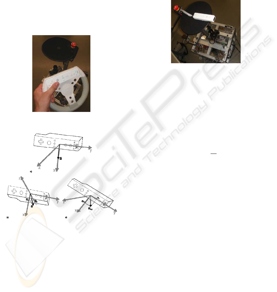
It is possible to determine how the remote is
tilted by sensing the gravitational force. Starting
position is measured and differences from that time
on are measured (figure 2.a). When the remote is
tilted forward or backwards the gravitational
acceleration is measurable over x and y axis (shown
figure 2.b). A leftward or rightwards tilt is
represented in figure 2.c. The y and z axis
accelerations are used to distinguish situations.
Figure 1: Wiimote Steering Wheel.
Figure 2: Gravitational vector: a) center position; b) tilt
forward; c) tilted leftward.
To control operations in this mode, a PD fuzzy logic
controller (based on the Mamdani architecture) was
implemented. This approach is interesting due to the
non-linearity associated with this movement
classification. The x, y and z values are the
acceleration on the respective axis. The rule base of
such controllers are defined by if-then rules that uses
triangular definitions for P=Positive, Z=Zero or
N=Negative sets on the v and ω variables for each
axis x,y,z.
3.2 Infra-Red Monitor
In this mode the Wiimote is attached to the robot
and its infra-red receiver is used to detect two infra-
red sources and measure their position. In order to
do this it is necessary to know the distance between
the two IR LEDs (d) and the flat angle on the xz
plane of the remote’s IR receiver (φ=43.8º).
Figure 3: Wiimote attached to the robot's body.
Through the relation between the distances d, in
centimeters, and the measured distance between the
two IR sources, in pixels, it is possible to calculate
r
2
. By knowing the relation between the horizontal
resolution of the image received by this sensor,
1024, and the angle associated with it, φ, it is
possible to determine θ through its relations with r
2
.
With these two variables it’s easy to calculate the
distance r
1
:
2
1
tan
r
r
θ
=
(1)
This operating mode can also be used to send
information to the self-location algorithm since it
can measure distance to walls marked with IR light
sources or to IR beacons, thus improving that
algorithm quality.
The main usage of these ideas is to implement a
follow-the-leader mode. In this mode the IR sources
are mobile and the distances r
1
and r
2
, measured by
the Wiimote’s IR receiver, are used to calculate the
velocities υ and ω, in order to keep it, and the robot
in which he is attached, at a fixed distance and
orientation relatively to the sources. This is done
using the fuzzy controller from the fuzzy steering
wheel mode. The mobile IR source is composed of
two IR led’s (ref. HIRL5020) connected to a 7,2V
source composed of six AA batteries. In average, the
batteries last 8h on continuous work.
ICAART 2009 - International Conference on Agents and Artificial Intelligence
346
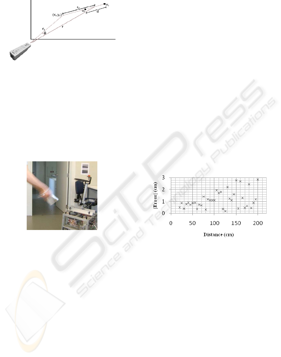
Figure 4: Schematic of the Infra-Red Monitor’s variables.
3.3 Movement Identifier
In the Movement Identifier mode, the tridimensional
accelerometer is used to read and save the
accelerations on each axis. Movements are classified
as one out of 13 pre defined situations. The
predefined movements are: single stroke linear - left,
right, up, down, front and back; repetitive left and
right, up and down and front and back; circular
movements and square shapes on the xz plane (clock
and counter clockwise).
Figure 5: Controlling the CleanRob with movements.
The acceleration’s graphic of a linear movement
over an axis will be similar to a one-period sine
wave. Detection is made by detecting maximum and
minimums.
The analysis of the other movements is more
complex but can be simplified if they are considered
as successive and simultaneous linear movements
over one or more axis.
The control method used to put this theory into
practice was Case Based Reasoning (CBR) based on
the model presented in (Aamodt, A. and Plaza, E,
1994). The attributes considered on each case were
the following:
• Max + Min count and peak values
• Positive and Negative amplitude (max peak –
min peak) centered on the average of the signal
• Time difference between peaks
• Peak sequence over time (several axis)
• Peaks of projected accelerations over XY plane
and angle from acceleration vector to XY plane
This mode will allow for detection of higher
level control actions.
4 RESULTS
The Steering Wheel allowed the user an easy way to
control the robot’s movement, although it was hard
to stop it due to the constant movement, voluntary or
involuntary, of the user’s hands. To make stopping
the robot an easier task it was created a threshold
around the υ and ω zero values. To ensure that the
control is not triggered involuntarily, its start and
stop is done by pressing the Wiimote’s A button.
The Infra-Red Monitor isn’t capable of detecting
IR light sources closer than 20cm from the Wiimote.
The results of the measurements error module are
presented in the figure 6. Notice this module is never
greater than 3cm but as a tendency to increase as the
distance between the IR sources and the receiver
increases.
Figure 6: Infra-Red Monitor measurement error.
To test the movement identification algorithm it
was necessary to compile the case base with
examples of all the thirteen movements that we want
to identify. In order to maximize the test of this
algorithm, the movements sent into the case base
were from only one person. Since how a movement
is done varies from person to person, which will
result in different acceleration vectors thus leading
to different values of the considered attributes, by
having only movements done by one person in the
case base it will be possible to analyze if the
attributes used in the CBR algorithm allow the
consistent identification of different movements,
even if there aren’t any movements in the case base
that were done that way.
The commands were thoroughly explained but
no teaching of the testers was done and most of the
testers were holding a Wiimote for the first time.
The results shown in the figure 7 prove that the CBR
HUMAN-MACHINE INTERFACE TO CONTROL A ROBOT WITH THE NINTENDO WII REMOTE
347
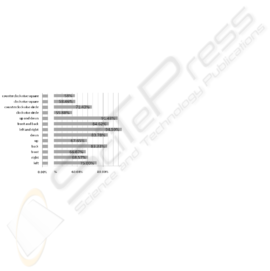
algorithm and the attributes mentioned before can be
used to correctly identify movements made by
people whose movements are not listed in the case
base. The proposed algorithm can distinguish the
movement’s orientation and can distinguish squares
from circles and in which direction they were done.
After this analysis, it was noted that most
incorrect identifications where due to bad input data.
It was mentioned that a linear movement over an
axis resembles a one-period sine wave and that
information was used in the development of the
CBR identifier, but if the data received isn’t
minimally similar to that sine wave, if it resembles a
slope for instance, the movement’s attributes will
make the system answer incorrectly. This can be
avoided if the user starts and ends the movement
with the Wiimote stopped. Another cause of bad
data is the speed at which the movement is done.
Low velocities will result in lower accelerations that,
when combined with the Wiimote’s accelerometer
low signal-to-noise ratio (SNR), will result in bad
attributes that will make the system answer
incorrectly.
…
Figure 7: Correct identification percentage of linear
movements by the CBR algorithm.
5 CONCLUSIONS
An implementation of a local human-robot interface
based on the Nintedo Wii’s remote controller was
presented. Due to the Wiimote features, it is easy to
use and inexpensive.
Three working modes were developed:
• The steering wheel allowed the user to set
references for v and
ω
in order to remote control
the robot in an intuitive way
• The “Follow the Leader” mode that uses
distance and angle to the “leader” and is
interesting to lead the robot to distant locations
quickly teaming up with the leader
• The “Movement Identifier” is an interface
usable in future for general commands.
The first two methods use a fuzzy controller. The
movement identifier uses Case Based Reasoning.
User tests hint that system usability is easy.
In the future, new working modes might be
added to the interface as well as new movements.
Another possibility is to allow for multiple
Wiimotes. It will also be very interesting to use the
Wiimote’s speaker to feedback perceived commands
to the user.
ACKNOWLEDGEMENTS
This work was partially supported by FCT Project
PTDC/EIA/70695/2006 "ACORD - Adaptative
Coordination of Robotic Teams".
REFERENCES
O. Mayora-Ibarra 2003. From HCI to HRI - Usability
Inspection in “Multimodal Human-Robotics
Interactions”, Proceedings of the 2003 IEEE
International Workshop on Robot and Human
Interactive Communication.
Perzanowski, D.; Schultz, A.C.; Adams, W.; Marsh, E.;
Bugajska, M. 2001. Building a Multimodal Human-
Robot Interface, in Intelligent Systems,IEEE, vol. 16,
Issue 1, Jan-Feb 2001 pp. 16 – 21.
Sousa, A. 2006 - CleanRob project official website.
Available at http://paginas.fe.up.pt/~cleanrob.
D. Driankov, 1996 An Introduction to Fuzzy Control –
Second Edition, Berlin, Springer, 1996, chapters 2,3
and 4.
Jenson, J., 2005. Design of Fuzzy Controllers in European
Network for Fuzzy Logic and Uncertainty Modeling in
Information Technology,
http://www.iau.dtu.dk/~jj/pubs/design.pdf
Aamodt, A. and Plaza, E, 1994. Case-Based Reasoning:
Foundational Issues, Methodological Variations, and
System Approaches in Artificial Intelligence
Communications 7, no. 1, 1994, pp. 39-52
ICAART 2009 - International Conference on Agents and Artificial Intelligence
348
