
Supporting View-Based Development through
Orthographic Software Modeling
Colin Atkinson, Dietmar Stoll and Philipp Bostan
Institute of Computer Science, University of Mannheim
68131 Mannheim, Germany
Abstract. Although they are significantly different in how they decompose and
conceptualize software systems, one thing that all advanced software engineer-
ing paradigms have in common is that they increase the number of different
views involved in visualizing a system. Managing these different views can be
challenging even when a paradigm is used independently, but when they are
used together the number of views and inter-dependencies quickly becomes
overwhelming. In this paper we present a novel approach for organizing and
generating the different views used in advanced software engineering methods
that we call Orthographic Software Modeling (OSM). This provides a simple
metaphor for integrating different development paradigms and for leveraging
domain specific languages in software engineering. Development environ-
ments that support OSM essentially raise the level of abstraction at which de-
velopers interact with their tools by hiding the idiosyncrasies of specific edi-
tors, storage choices and artifact organization policies. The overall benefit is to
significantly simplify the use of advanced software engineering methods.
1 Introduction
In an effort to accommodate the ever growing demand for more complex and feature-
rich applications, and to develop software in more cost effective and systematic ways,
in recent years the IT industry has experimented with various new paradigms for
software engineering. Chief amongst them are model-driven development, compo-
nent-based development, product line engineering (PLE) and aspect-oriented devel-
opment. They each use a different combination of abstraction and (de)composition
techniques to break a large complex system or family of systems into manageable
pieces. However, one thing they all have in common is that they increase the number
of artifacts or “views” involved in the software engineering process. Model-driven
development introduces views at various levels of platform specificity together with
transformations between them, component-based development introduces internal and
external views of software components as well as their compositions, PLE introduces
family wide and product specific views of systems and the feature choices that relate
them, and finally aspect-oriented development introduces a view of functional and
cross cutting elements of a software system and how they are woven together.
Atkinson C., Stoll D. and Bostan P. (2009).
Supporting View-Based Development through Orthographic Software Modeling.
In Proceedings of the 4th International Conference on Evaluation of Novel Approaches to Software Engineering - Evaluation of Novel Approaches to
Software Engineering, pages 71-86
DOI: 10.5220/0001953200710086
Copyright
c
SciTePress

Even when used alone, therefore, these new methods increase the need to define
and manage multiple views, but when two or more of these methods are used togeth-
er, the number of views quickly explodes out of control. The current view generation
and management approaches of most case tools are wholly inadequate to deal with
these challenges, however. First, few if any have a concrete idea of what views
should be created in a development project, what contents they should contain and
how they should be related. Secondly, most have a fixed, hardwired definition of
what view types are possible (e.g. UML diagrams, annotated code and aspects etc.).
Thirdly, most provide ad-hoc techniques for maintaining consistency between views
and do so on a limited, pair wise basis. While this might be feasible for small num-
bers of views, it does not scale to large numbers.
We believe that one of the next major steps forward in software engineering will
be driven by tools and methodologies that provide a systematic and flexible approach
to view generation and management. To do this we believe the next generation of
tools needs to support:–
1. Dynamic View Management
2. Dimension-based View Navigation
3. View-oriented Methods
We are currently developing an approach for doing this that we refer to as Ortho-
graphic Software Modeling
1
(OSM). The name is motivated by the orthographic pro-
jection approaches used in CAD tools to visualize physical objects. In this paper we
describe the basic idea behind OSM and explain how the tool that supports it meets
the three basic requirements outlined above. We then present a small case study that
illustrates how OSM might work in practice.
2 View-based Software Engineering Method
To provide the context for the first two requirements (dynamic view management and
dimension based view navigation), in this section we first provide an overview of the
view-based method that we are currently trying to support. This is an updated version
of the KobrA method [1], KobrA 2.0 [2], enhanced to exploit UML 2 and the latest
software implementation technologies such as web services. In this section we will
simply refer to this method as KobrA, with the understating that we are referring to
the latest version. This is just one of many possible methods that can be supported by
OSM tools, however. In fact, in principle, any method could be supported by an OSM
tool, since every method requires some kind of view of the software to be manipu-
lated (e.g. the source code).
1
We use “model” in a general sense to include any human-readable representation of a soft-
ware artefact. This includes, but is not limited to, UML models.
72

2.1 KobrA
KobrA was developed with the goal of integrating model-driven development
(MDD), product line engineering (PLE) and component-based development (CBD)
[3] in a systematic way. To do this KobrA explicitly identifies three fundamental
dimensions, each representing an aspect of a system’s description that could vary
independently of the others.
The core dimension is the composition dimension in which (de)composition of the
system into components is elaborated (CBD). The second most important dimension
is the abstraction (or platform specificity) dimension in which the system is described
at different levels of platform specificity (MDD). The final dimension is the generici-
ty dimension in which the system is described in both generic (i.e. family level) and
specific (i.e. application level) forms (PLE). In principle, each dimension can vary
independently, i.e. they are orthogonal to one another. The key idea in KobrA is that
these conceptually orthogonal “dimensions” should be made explicit and that differ-
ent views of the system should be located somewhere in this space. As a UML based
method, KobrA also defines strict principles for using UML diagrams to view differ-
ent aspects of a component from different perspectives.
As shown in Figure 1, the views of a component are separated into two distinct
groups – those showing properties that can be seen from the outside by users of the
component (i.e. from a black box perspective), and those showing the properties that
can be seen from inside by the developer of the component (i.e. from a white box
perspective). The former group is known as the specification and the latter as the
realization. The black box and white box perspectives of a component have further
substructure as also represented in Figure 1. Basically each contains three different
views, or projections, which describe different kinds of information about the com-
ponent. The structural projection shows structural information using UML class dia-
grams. The operational projection shows information about the functionality of each
operation modeled in the form of operation specifications and interaction diagrams.
The behavioral projection focuses on the sequencing and algorithmic properties of the
component as manifest by state charts and activity diagrams. Although these were not
viewed as “dimensions” in the original version of KobrA, during the development of
KobrA 2 it was realized that the separation between black box and white box perspec-
tives, and the separation of information into different projections (or different aspects
of description) that can vary independently, represent dimensions in the sense used
above.
Generic components (for PLE) are described by adding an additional view, known
as the decision model, to the views already illustrated in Figure 1. The decision model
describes the different variants of the system in terms of decisions that the user can
make to decide which features he or she would like. Dependencies between decisions
can be specified using OCL constraints [4].
73

Structural View
(UML class/object
diagrams)
Operational View
(operation specifications)
Behavioral View
(UML statechart diagram)
Specification
Business
Component
Structural View
(UML class/object
diagrams)
Operational View
(UML collaboration
diagrams)
Behavioural View
(UML activity diagrams)
Realization
Fig. 1. Component description views.
For example, it can be specified that one decision should automatically be resolved
when another one is resolved. A decision is further described by its possible Resolu-
tionSet. A resolution set represents the range of values (e.g. Boolean, Range or Valu-
eSet) that can be assigned to a decision when defining a particular variant. The effects
of each possible resolution value on the other views are defined, such as the removal
of model elements like classes, methods or even whole components. With a generic
component, every model element that is variable and represents a variation point is
marked by the stereotype <<variant>>. To create specific components from the ge-
neric component, the associated decision model needs to be resolved by specifying
the appropriate values of the available ResolutionSet.
2.2 KobrA Dimensions
Thanks to its principles of separating concerns and defining how different UML/OCL
diagrams can be used to portray different views of a system, KobrA is an ideal basis
for OSM. Indeed, our vision of an OSM modeling environment was originally moti-
vated by our aim to develop a tool to support KobrA. Although the original version of
KobrA did not take the idea of dimensions to its logical conclusion, and identified
each independently-varying criteria as a true dimension (e.g. the encapsulation levels
and the projections), this is an easy step to take. The modeling principles embodied
by KobrA naturally suggest the following five dimensions:
Composition. This dimension covers the (de)composition of components into sub-
components. Selecting a point along this dimension corresponds to the specification
of the component or subcomponent which is currently being worked on.
Abstraction. This dimension addresses the platform specificity of a view. In other
words, selecting a point on the abstraction dimension identifies the level of detail at
which the component is being viewed. In principle there can be multiple points along
this dimension, but the most important are platform independent model (PIM), plat-
form specific model (PSM) and implementation. The KobrA approach is mainly con-
cerned with the PIM level.
74

Encapsulation. The “public” encapsulation option provides a black box view of the
component. It describes all externally visible properties of a component and thus
serves as its requirements specification. The “private” encapsulation of a component
provides the white box view, and thus includes all the information in the black box
view.
Projection. This dimension deals with the types of information contained in a view.
The projections currently available are the structural, operational, behavioral and
variational projections. The latter contains the decisions that determine what aspects
of a component’s description are included in a specific variant and which parts are
not.
Variant. This dimension enumerates the different variants of a system when follow-
ing a product line approach (e.g. “Mobile Edition”, “Enterprise Edition”). In addition,
the generic variant includes all possible features of the system and a decision model
for each component. Each particular variant is then associated with specific decision
resolution models, which are resolved in application engineering.
The KobrA method was designed before the notion of OSM was developed as a
notion for supporting and characterizing view-based development environments, and
is theoretically independent of it. However, we believe that KobrA needs to be sup-
ported by such an environment to be used effectively. In the following two sections
we explain how the two key ideas for achieving this are realized.
3 Dynamic View Management
Early work on view-based software engineering came to the conclusion that it was
not cost effective to derive views of software artifacts dynamically from a single
underlying model or representation [5]. However, since this work was carried out, the
power of processors and availability of storage has increased tremendously, and new
technologies have emerged that specialize in performing transformations between
different models – so called model-driven development. Software development is also
increasingly becoming a collaborative activity, with multiple developers working
concurrently on different aspects of a system on different computers. We believe
these developments change the situation, and make the dynamic, on-demand genera-
tion of views practicable.
Our approach is based on the idea of creating a Single Underlying Model (SUM)
that contains all information about the system currently available, and separates view
models that contain the information to be displayed into specific views of the system.
When a new view is opened it is generated dynamically from the SUM via the appro-
priate transformation, and when new information about the system is added to the
view this is eventually added to the SUM. To ensure that all views are kept up up-to-
date with the SUM, and thus consistent with each other, the publisher/subscriber (or
observer) pattern is used to notify open views when they need to update themselves.
75
This basic principle of “on-demand” generation from a single underlying model is
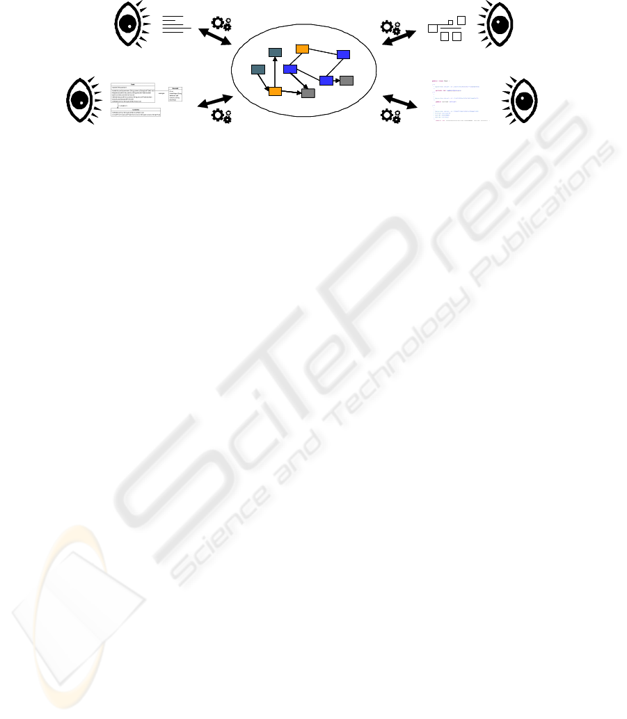
depicted in Figure 2.
Java sourceJava source
UML classesUML classes
Fig. 2. On-the-fly generation of Views.
The boxes and arrows within the ellipse in the center of Figure 2 are meant to
represent the data elements making up the SUM. Each of the four shown views is
generated dynamically by means of the appropriate transformation whenever the
developer wishes to see the view. No effort is needed to keep views consistent in a
pairwise basis, because as long as each is consistent with the SUM, it is consistent
with all the other views. We also regard traditional source code as a view, just like
any other. Since high-level views (e.g. models) can be generated at any time, for
example after changes have been added via a code view, this approach provides inhe-
rent support for “round trip” engineering.
3.1 SUM and View Metamodels
The metamodel for the SUM defines the concepts used to describe the properties of a
software system in the chosen method. The SUM metamodel is thus method specific,
and in this case therefore captures the concepts needed by the KobrA method. Since
this is a UML centric method, it makes sense for the SUM to be defined as a speciali-
zation of the UML. As an example, the UML 2 Association metamodel element is
reused. It is further specialized into Creates, Acquires and Nests, which describe
relationships between KobrA Components and KobrA Classes. Acquires, for exam-
ple, is then constrained using OCL to ensure that only a KobrA Component can ac-
quire another Component (or KobrA Class) and that a KobrA Class is prohibited to
acquire anything. Elements from UML 2 that are not needed for our development
method are also excluded using OCL constraints. New elements introduced in the
metamodel are specialized from UML 2 elements and then further described and
constrained.
From the point of view of standard MDD technology, a view is a normal model
which just happens to have been generated dynamically for the purpose of allowing a
user to see the system from a specific viewpoint. The only other requirement is that
the model has to have an associated concrete syntax by which it can be rendered. This
can be a graphical syntax, such as the UML, or a textual syntax, such as a program-
ming language like Java. A view can be represented in a general, standardized model-
ing language like the UML that can be rendered by many tools, or it can be
76

represented in a highly specialized language that is specific to one single tool. Since
the transformation technology used to generate and update the views can work with
any source and target metamodels, there is no theoretical constraint on what languag-
es and tools can be used. From a tool integration point of view, however, it is more
practical to use rendering engines and editors that are part of the same IDE family
(e.g. Eclipse [6]) and/or that work on related languages (e.g. EMF or OMG metamo-
dels). Like the SUM, the view metamodels are all accompanied by extensive OCL
constraints that define the concrete well-formedness rules that instances of the meta-
models must obey.
3.2 “On-the-fly” View Generation
The key technology that makes the dynamic generation of arbitrary views practical
are the transformation languages and engines provided by MDD environments. These
allow users to add new views to their environment in a straightforward way by defin-
ing how a view is generated from the SUM and what well-formedness rules it must
adhere to. While the writing of transformations is a non-trivial task, we believe that it
will involve far less effort than the consistency checking and verification activities
(e.g. inter-view consistency checking) that would otherwise have to be performed
manually. Any convenient transformation language can be used. We currently use the
ATLAS Transformation Language (ATL) [7].
For “read only” views it is only necessary to define a transformation in one direc-
tion – from the SUM to the view. However, when views can also be edited, it is ne-
cessary to define reverse transformations as well. The role of the reverse transforma-
tions is to add new information about the system entered via a view to the SUM. This
takes place whenever the developer working with the view indicates that they would
like to “commit” the changes that they have made to the SUM. Changes can be made
at various levels of granularity, from very fine-grained changes such as a name-
change to very large-grained changes where a large piece of the model is modified.
The choice reflects a balance between efficiency and the risk that changes may be
inconsistent with those made by another developer working on a different view.
Since, in general, multiple views may be open at the same time, and may even be
worked on concurrently by separate users, a mechanism is needed to ensure that open
views are updated as soon as they potentially become out of date. This can be
achieved by the straightforward application of the publisher-subscriber (or observer)
subpattern of the Model-View-Controller (MVC) architectural pattern. Finally, in
order to keep track of the history of changes made to the SUM, a transactional ver-
sioning system is needed. Again this can be based on a standard versioning system
such as CVS or subversion, or on versioning systems specifically tailored to the
SUM.
4 Dimension-based View Navigation
The Dimension Based View Navigation scheme is perhaps the most novel aspect of
the orthographic modeling approach. It aims to mimic the way that users of CAD
77

tools can navigate around the views of a physical object by picking the different pers-
pectives and viewpoints from which they wish to see the object. Each view can be
thought of as occupying a single cell in a multi-dimensional cube, which is selected
by picking a position in each dimension. Figure 3 shows a schematic picture of such a
cube, but only with three dimensions. One dimension has two positions to choose
from, one has three positions to choose from and one has four. In general, the cube is
multi-dimensional and each dimension can have an unlimited number of positions.
The advantage of such a navigation approach is that it frees the developer from
having to work with the navigation tree of each individual tool used to view each type
of artifact. With dimension-based navigation each view is identified by its location in
the dimension space rather than its location in a specific tool’s artifact tree. Different
native tools are still used to work with each view, but these are invoked automatically
by the OSM tool as needed.
4.1 Dimensions
A dimension is any aspect of a software system’s description that can vary more or
less independently of other aspects. We say “more or less” because the dimensions
are not always 100% orthogonal – there are sometimes combinations of options along
different dimensions that don’t make sense and thus are impossible to show to the
user as a view. In other words, some cells might be empty (have no view).
The multi-dimensional cube is manifested in the GUI as a set of separate lists, each
holding the different options for a given dimension. To select a cell, the user therefore
simply has to select an option from each list. Figure 3 (right-hand side) shows how
orthographic navigation around KobrA artifacts might be supported from a GUI pers-
pective. Each list on the left hand side represents the possible choices in each dimen-
sion, and the diagram on the right hand side represents the actual view.
It is a design decision of the GUI how to deal with empty cells for which no views
can be generated. To this end, we allow dependencies to be defined between dimen-
sions, i.e. the selection of elements in a dimension of higher precedence might restrict
or change the possible selections in dimensions of lower precedence. The higher a
dimension is listed on the left hand side, the higher is its precedence.
4.2 Language and Notation
The top five dimensions in the IDE shown in Figure 3 represent the KobrA-oriented
views that were described in section 2. In a sense they define the logical views of the
system supported in KobrA, because they characterize the basic nature of the infor-
mation that can be seen in each view, but they do not deal with how it is presented.
This is the job of the last two dimensions. They are an OSM tool’s mechanism for
dealing with the different language and notation options that can be used to depict a
logical view.
78
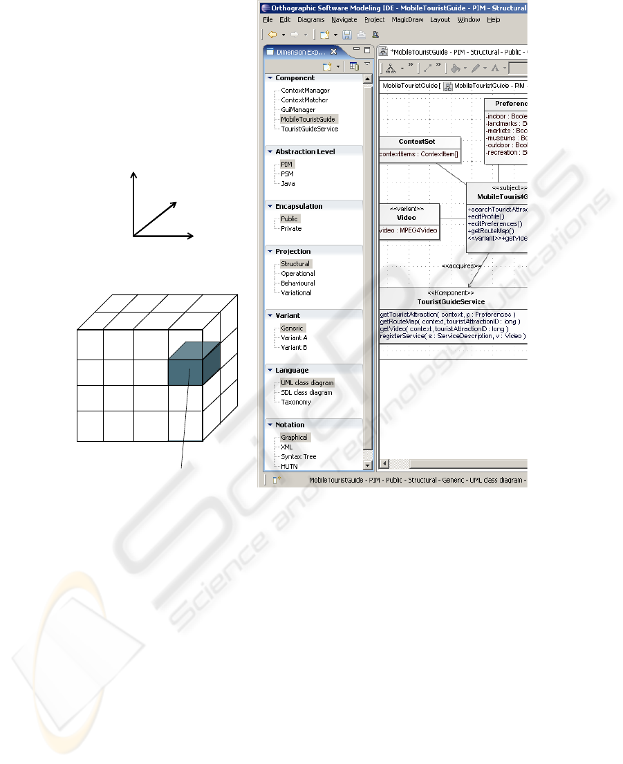
Fig. 3. Component navigation and Orthographic Software Modeling IDE.
The language dimension identifies the basic language used to depict a view. We
use “language” here in the general sense used in the “domain specific language” field
to represent any formal language for representing information. This includes pro-
gramming languages like Java and modeling languages like UML. Since it was
oriented towards the UML, the original KobrA method envisaged that UML classes
would be used to represent the structural view. However, in general, any suitable
structural modeling language could be used such as SDL or OWL.
Identifying a language still does not provide all the information needed to depict a
view because most languages can be rendered using various concrete syntaxes. For
example, as well as the well known graphical syntax, UML diagrams can also be
represented in a textual form such as XMI or a human readable textual notation such
as HUTN. Even programming languages like Java can be rendered in various forms,
for example in XML or JavaDoc. The final dimension therefore defines the concrete
notation used to depict a view.
Cell
Component-based
Software System
Dimension
Dimension
D
i
m
e
n
s
i
o
n
Dimension
Dimension
D
i
m
e
n
s
i
o
n
79

Internally, the OSM tool keeps track of which default editor should be used to de-
pict each view, so that once language and notation choices have been made, the sys-
tem can automatically invoke the editor needed to show the view on the right hand
side. In Figure 3, MagicDraw [8] is used for a UML class diagram. Since OSM pro-
vides inherent support for identifying languages and notations when working with
views, it provides a natural metaphor for integrating domain specific languages into
software engineering environments.
4.3 Dimension Definition
The dimensions and their ordering/dependencies capture the characteristics of a de-
velopment methodology. We therefore believe that different companies will want to
tailor and define their own dimensions. Thus, the dimension structure is stored in a
general data structure that can be configured by the user.
A common tailoring scenario is to add new languages and notations to the envi-
ronment. One could for example add a component descriptor editor, which manages
general component information, for the PIM – Public – Structural combination. A
new language and notation can be added in the simplest case by adding a new meta-
model for the language, a notation and associated transformations for the generation
and synchronization of the editor’s data. If the language enhances the development
approach by adding new concepts, new elements and new consistency checks might
also have to be added to the core metamodel of the SUM.
New dimension elements can be added by associating the appropriate dimension
combinations with existing editors. A new dimension element could be a new variant,
e.g. “Professional Edition”. Also, whole new dimensions could be added to existing
approaches, such as a version dimension, where each element represents a different
version of the component-based system.
5 Case Study
The case study is based on a context-aware mobile tourist guide that consists of a
mobile client and a server-side tourist guide service. The server stores information
about tourist attractions and service descriptions that can be registered at the service.
The goal of this section is to show the various kinds of views that can be used to
visualize the system, and how they are reached via the dimension-based navigation
metaphor.
5.1 Mobile Tourist Guide – Black Box
We start the case study by developing artifacts for the black box model of a compo-
nent at the PIM level, so we select Public from the Encapsulation dimension and PIM
from the Abstraction dimension.
In the Component dimension we create the top level component MobileTourist-
Guide as a new dimension element. Since we start with the structural description of
80
the publicly visible parts, the Projection dimension is set to Structural. In the Variant
dimension, we select the Generic version of the MobileTouristGuide. Once this cell
of the conceptual cube has been selected, the system offers an appropriate “editor” for
the view – in this case a UML class diagram editor.
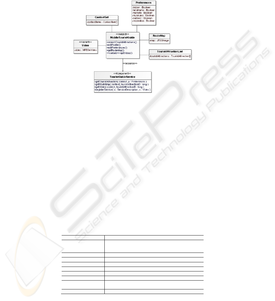
Fig. 4. MobileTouristGuide – PIM – Public – Structural – Generic – UML Class Diagram –
Graphical.
Figure 4 shows the UML class diagram. It features the MobileTouristGuide which
is the “subject” according to KobrA’s principle of locality [1]. The specification of a
component only includes associations to externally visible components (marked in the
association by the stereotype <<acquires>>). Furthermore, this specification contains
an association to a variant class (Video) and a variant method (getVideo) marked by
the stereotype <<variant>>. The stereotype can be applied to whole components, to
single methods or to variables. These represent variation points that are administrated
by the decision model which is also presented in this section.
Every method of the MobileTouristGuide can be described further with an Opera-
tion Specification editor. The operation specification is publicly visible and is part of
the Operational projection. It is described in tabular form as shown in Table 1. The
Operation Specification Editor of the IDE offers some additional features like syntax
checking for OCL pre- and postconditions.
Table 1. MobileTouristGuide – PIM – Public – Operational – Generic – Operation Specifica-
tion – Tabular.
Name
searchTouristAttractions
Description
Searches for tourist attractions depending on the user’s
preferences and the current context (e.g. location, time,
weather)
Receives
-
Returns
TouristAttractionList
Sends
TouristGuideService.getTouristAttraction()
Reads
ContextSet, Preferences
Changes
TouristAttractionList
Body
-
Precondition
Preferences have been set up, Context Sources are
available
Postcondition
TouristAttractionList contains suitable attractions
81
5.2 Mobile Tourist Guide – White Box
The artifacts of the public encapsulation (i.e. black box information hiding) view of a
component describe what a component does, i.e. what services it offers to users. The
artifacts of the private encapsulation describe how the promised functionality is rea-
lized, including interactions with (sub)components. To see the white box views of a
component we therefore need to set the Encapsulation dimension to Private. Like the
black box view in the previous subsection, the white box view contains a perspective
in which we can see the UML class diagram of the MobileTouristGuide, but this time
with additional elements needed for the realization.
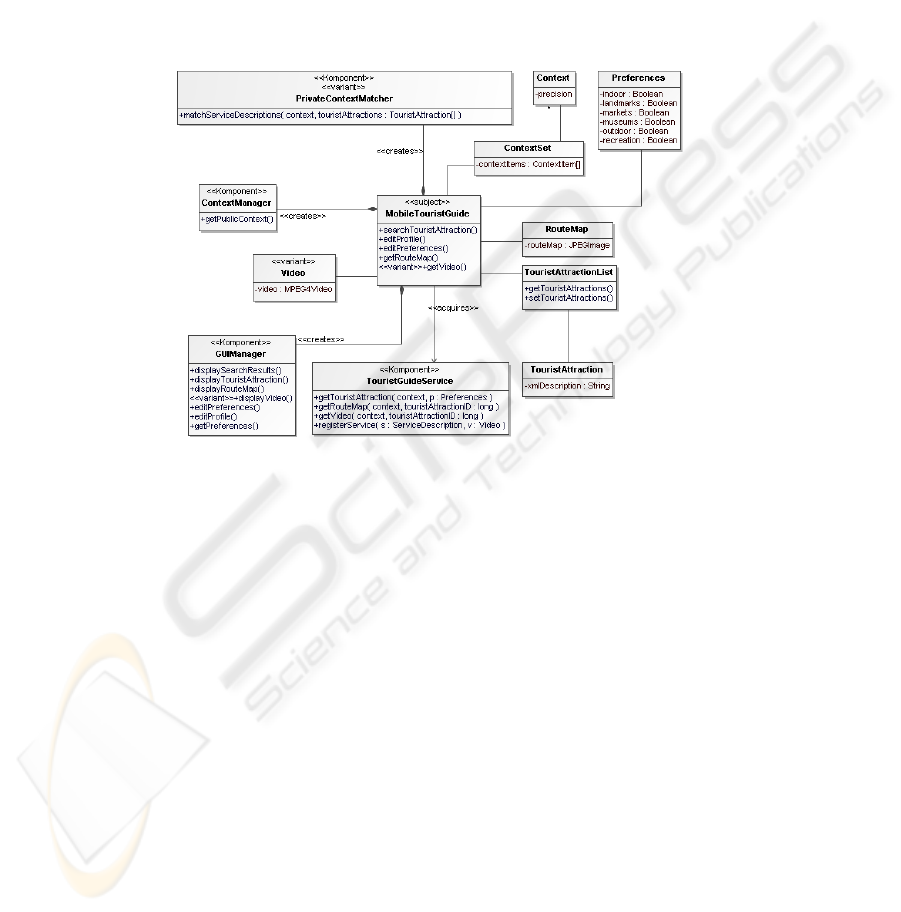
Fig. 5. MobileTouristGuide – PIM – Private – Structural – Generic – UML Class Diagram –
Graphical.
In general, the operational projection contains a UML communication or sequence
diagram which shows how a particular function interacts with other artifacts of the
system. The behavioral projection shows the algorithm of a particular function using
a UML activity diagram.
We start again with the structural projection of the MobileTouristGuide, depicted
as a UML class diagram in Figure 5. The dimension Variant is included in the generic
model using the stereotype <<variant>> as in the black box view to mark variation
points that are used in the decision model for variants of a product family. In addition
to the mentioned relationship <<acquires>> which expresses the fact that the subject
needs the acquired component to fulfill its own mission, a new relationship, called
<<create>>, between components is introduced in Figure 5. This relationship declares
that the subject is fully responsible for the subcomponent, i.e. its creation and destruc-
tion.
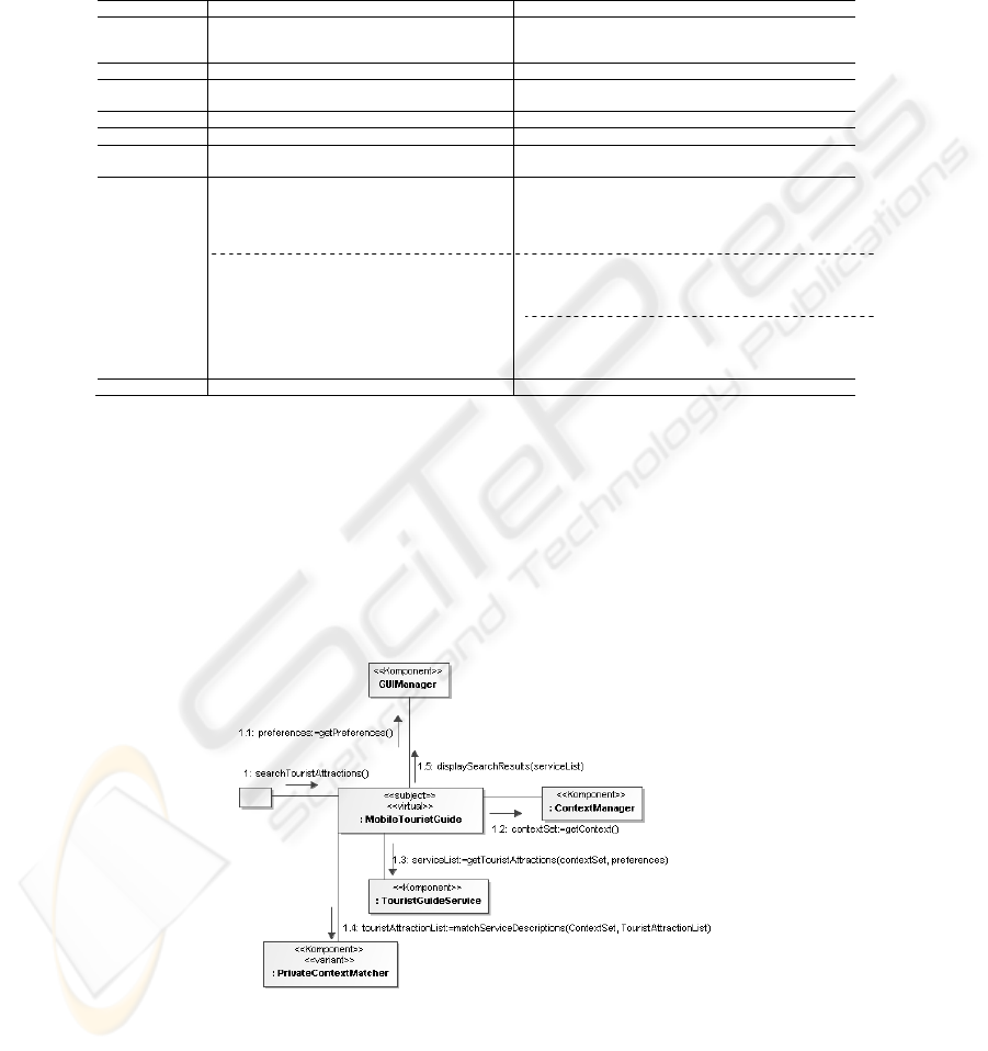
In Figure 6, a UML communication diagram is shown that illustrates the interac-
tion with other components for the operation searchTouristAttractions() which be-
longs to the component MobileTouristGuide.
82
The decision model is associated with the Variational projection and, as the deci-
sions are not yet resolved, the Generic variant. As mentioned before, the variation
points of a component are administrated via the component’s local decision model.
Table 2. MobileTouristGuide – PIM – Private – Variational – Generic – Decision Model –
Tabular.
In Table 2, the private encapsulation decision model of the MobileTouristGuide is
shown for the structural projection. It contains questions that have to be resolved in
order to create actual product versions. The example shows a decision that is related
to two variation points and another decision related to three variation points. For
each, the given ResolutionSet defines the possible values that can be assigned within
a decision. The effects clause specifies which action is performed dependent on the
resolution value. In this example effects are applied to the UML class diagram shown
in Figure 5 and the UML communication diagram shown in Figure 6.
Fig 6. MobileTouristGuide – PIM – Private – Operational – Generic – UML Interaction Dia-
gram – Graphical.
1 2
Description
Is the mobile client device capable of playing
videos?
What visibility should be assignable to context items
on the mobile client? (Public context items are
transmitted to the server, private context items not)
Component
MobileTouristGuide MobileTouristGuide
Encapsula-
tion
Private Private
Projection
Structural Structural
Constraints
-- --
Resolution-
Set
Boolean ValueSet {Public, Private, PublicAndPrivate}
Effects
ResolutionValue: True
(1) remove stereotype <<variant>> at Class Video
(2) remove stereotype <<variant>> on operation
MobileTouristGuide.getVideo()
ResolutionValue: False
(1) remove Class Video
(2) remove operation MobileTourist-
Guide.getVideo()
ResolutionValue: Public
(1) remove <<Komponent>> PrivateContextMatcher
(2) remove association PrivateContextMatcher-
MobileTouristGuide
ResolutionValue: Private
(1) remove stereotype <<variant>> at Ko
PrivateContextMatcher
ResolutionValue: PublicAndPrivate
(1) remove stereotype <<variant>> at Ko
PrivateContextMatcher
Stakeholder
Application Engineer Application Engineer
83
The next step in hierarchical decomposition, according to the principles of KobrA,
is to create a black box view for each subcomponent shown in the white box view of
the MobileTouristGuide in Figure 5.
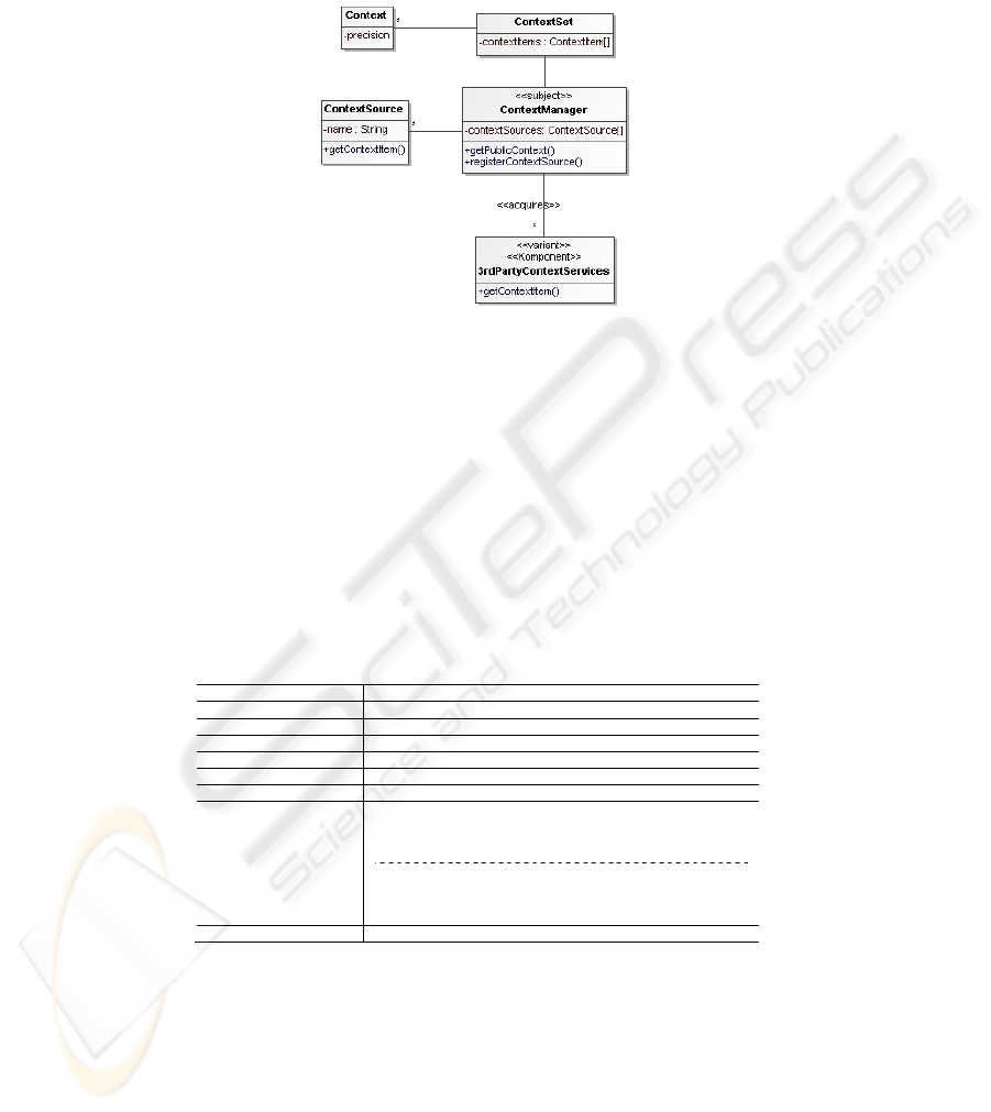
Fig. 7. ContextManager – PIM – Public – Structural – Generic – UML Class Diagram –
Graphical.
As an example, Figure 7 shows the structural view of the ContextManager as a
UML class diagram. This follows the principle of parsimony which means that the
ContextManager becomes the subject of the perspective and only those components
are shown that the subject requires. For the purpose of our case study we limit the
explanation of subcomponents to the ContextManager component. Decomposition for
the other components is equally straightforward. In Table 3, the public decision reso-
lution model of the ContextManager is shown. It contains the decisions which are
related to the component’s black box view.
Table 3. ContextManager – PIM – Public – Variational – Generic – Decision Resolution
Model – Tabular.
ID
3
Description
Is the mobile client device capable of playing videos?
Component
ContextManager
Abstraction
Specification
Projection
Structural
Constraints
--
ResolutionSet
Boolean
Effects
ResolutionValue == True
(1) remove stereotype <<variant>> at Komponent
3rdPartyContextServices
ResolutionValue == False
(1) remove Komponent 3rdPartyContextServices
(2) remove association 3rdPartyContextServices-
MobileTouristGuide
Stakeholder
Application Engineer
6 Conclusions
In this paper we have presented a new paradigm for organizing the many views that
need to be manipulated in modern software engineering methods and have outlined
84

the key features of a tool to support it. Known as orthographic software modeling,
the approach mimics the orthographic projection principle used in CAD tools to vi-
sualize physical engineering artifacts. By doing so, it raises the level of abstraction at
which developers interact with tools by hiding the idiosyncrasies of specific editors
and tools. We have built a prototype version of this tool in Eclipse, using a heteroge-
neous mix of well known editors to render and manipulate specific views, such as the
Eclipse Java editor for Java views, and MagicDraw for UML-oriented views. We are
currently implementing a more generic view generation engine using a transformation
language and ultimately aim to reduce the number of native tools to zero.
To the best of our knowledge, there is currently no approach that combines on-
demand view generation with the approach of dimension-based navigation. [9] fea-
ture a systematic, hierarchical modeling approach and a tool with a fisheye zooming
algorithm that allows models to be visualized with different levels of detail. There are
some similarities, e.g. the classification in structural and behavioral views. However,
the development approach mainly uses non-UML views for structural and behavioral
aspects of a software system while the KobrA method makes heavy use of UML
diagrams. Also, it does not (yet) deal with product line engineering. The KobrA book
[1] gives an overview of other related approaches such as OMT [10], Fusion [11], or
Catalysis [12]. One particularly interesting modeling paradigm is the Real-Time Ob-
ject-Oriented Modeling (ROOM) [13]. It allows decomposition in a systematic way,
e.g. by allowing actors at one level to be the realization of actors at a higher level.
However, it is unclear about certain object modeling concepts and also gives only few
hints about the development time organization of software artifacts.
Our approach includes an extensible navigation concept where customized dimen-
sions, dimension elements, languages and notations can be integrated in a systematic
and straightforward way. It also allows the users to define a dominance hierarchy
between the dimensions such that dimensions near the top of the architecture influ-
ence what is available for dimensions lower in the hierarchy. Indeed, it is possible
that a choice in a higher level dimension may remove a lower dimension completely
(because all the cells for that row are empty). We believe that this definition of di-
mension dominance relationships and dependencies actually goes a long way to cap-
turing the core ideas that underpin a paradigm. For example, in an MDD focused
project, the abstraction dimension would be the most dominant, whereas in a product
line engineering oriented project, the variant dimension would dominate. We there-
fore believe that OSM tools are inherently able to support multiple paradigms, and
thus can be used as a vehicle for bringing them together, or using them in different
phases of development, whatever best fits the needs of the project in hand.
References
1. Atkinson, C., Bayer, J., Bunse, C., Kamsties, E., Laitenberger, O., Laqua, R., Muthig, D.,
Paech, B., Wüst, J., Zettel, J.: Component-Based Product Line Engineering with UML.
Addison-Wesley Publishing Company, 2002
2. Atkinson, C., Brenner, D., Bostan, P., Falcone, G., Gutheil, M., Hummel, O., Juhasz, M.,
Stoll, D.: Modeling Components and Component-Based Systems in KobrA, in A. Rausch,
85

R. Reussner, R. Mirandola, E. Plasil (eds.): The Common Component Modeling Example:
Comparing Software Component Models, Springer, 2007
3. Szyperksi, C., Gruntz, D., Murer, S.: Component-Software – Beyond Object-oriented
Programming . Second Edition, Addison Wesley / ACM Press, 2002
4. Object Management Group: Object Constraint Language Specification, Version 2.0.
http://www.omg.org/cgi-bin/apps/doc?formal/06-05-01.pdf, May 2006
5. Finkelstein, A., Kramer, J., Goedicke, M.: ViewPoint Oriented Software Development, In
Proc. of 3rd Int. Workshop on Software Engineering and its Applications, Toulouse, 1990
6. Eclipse Development Platform, http://www.eclipse.org, visited May 2008
7. The ATLAS Transformation Language, http://www.eclipse.org/m2m/atl/, visited May 2008
8. MagicDraw, http://www.magicdraw.com, visited May 2008
9. Glinz, M., Berner, S., Joos, S.: Object-oriented Modeling with Adora. In Information
Systems, 27, 6, (2002), pp. 425-444, http://www.ifi.unizh.ch/req/ftp/adora.pdf, 2002
10. Rumbaugh, J., Blaha, M., Premerlani, W., Eddy, F., Lorensen, W.: Object-Oriented Model-
ing and Design, Prentice Hall, 1991
11. Coleman, D., Arnold, P., Bodoff. S., Dollin, C., Gilchrist, H., Hayes, F. and Jeremaes, P.,
Object-oriented Development. The Fusion Method, Prentice Hall, 1994
12. D’Souza, D. F. and Wills A. C., Objects, Components and Frameworks with UML: The
Catalysis Approach, Addison-Wesley, 1998
13. Selic, B., Gullekson, G., Ward, P.T.: Real-Time Object-Oriented Modeling, John Wi-
ley&Sons, 1994
86
