
INTERACTION OF A FLEXIBLE ROBOT WITH ITS
ENVIRONMENT
Michael Kastner, Hubert Gattringer, Hartmut Bremer
Institute for Robotics, Johannes Kepler University, Altenberger Strasse 69, 4040 Linz, Austria
Martin Ramsauer, Paolo Ferrara
FerRobotics Compliant Robot Technology GmbH, Altenberger Strasse 69, 4040 Linz, Austria
Keywords:
Fludic Muscles, Pneumatic Robot, Contact Detection, Interactive Programming, Human Robot Interaction.
Abstract:
Uncomplicated and safe programming interfaces as well as flexible programs themselves become important
when robots are used for small lot size tasks or are operated by personnel without special robotics education.
This work takes a look at safe and easy interaction of a flexible articulated robot arm – actuated by fluidic
muscles – with its environment. A contact detection scheme for stiff collisions at speeds between 50 and
250 mm/s is presented and measurement results are disucussed. Moreover, a programming by demonstration
concept is described on the basis of a pick and place task. Both strategies (implemented on a seven axis
handling robot) rely on physical models to allow an operation without extra sensors.
1 INTRODUCTION
Programming a robot requires a high level of subject-
specific knowledge and concentration. Human errors
can cause great damage to the robots environment –
including people. Studies showed that most robot re-
lated accidents occur during programming or fault re-
covery (Clark and Lehto, 1999). For small lot sizes,
frequent reprogramming and adaptation increases the
occurance of these scenarios, thus heightening the
overall probability of harm to process equipment and
personnel.
Fluidic muscles are interesting actuators for de-
vices interacting with humans, because of their com-
pliance. See (Daerden and Lefeber, 2002) for an tech-
nology overview and (Van Damme et al., 2005) for
more on soft manipulators. Besides safety considera-
tions coveredin (Bicchi and Tonietti, 2004), this com-
pliance can also be used to let the robot be more aware
of its surroundings.
For this paper we consider a robot actuated by
commercially available muscles (Hesse, 2003) of the
McKibben type. We show how the physical model
of the robot and its actuators can be used in two sce-
narios of robot environment interaction. This is done
without the need for any sensors in addition to the
ones present in the control loops (see Figure 1b).
In the first setting, the robot moves along a trajec-
tory at rather low speed and should be able to detect a
(stiff) collision with its surrounding at the tool with-
out causing damage. This sense of touch is meant to
free the programmer from the necessity to provide the
exact data of the process setup to the robot. Measure-
ment results for different speeds and spatial directions
are discussed.
The second part describes the direct interaction of
the operator with the robot to allow the programming
of a simple pick and place task completely by demon-
stration.
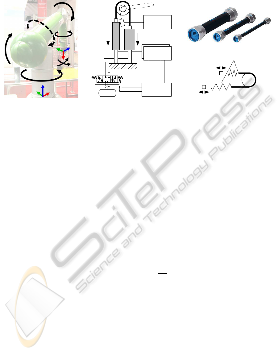
2 SYSTEM ARCHITECTURE
The robot configuration (1a) comprises seven rota-
tional joints. Five are actuated pneumatically. Of
these, three (1, 2 and 4) are driven by the one degree
of freedom muscle setup detailed below. The hand
joint (6, 7) is operated by a combination of three flu-
idic muscles and a cardan mechanism. The remaining
two joints (3, 5) contain standard brushless DC mo-
tors with harmonic drive gearing.
As shown in Figure 1b, a pneumatic muscle drive con-
sists of two muscles (Figure 1c) in an antagonistic
setup connected by a sprocket chain. The linear mo-
230
Kastner M., Gattringer H., Bremer H., Ramsauer M. and Ferrara P. (2010).
INTERACTION OF A FLEXIBLE ROBOT WITH ITS ENVIRONMENT.
In Proceedings of the 7th International Conference on Informatics in Control, Automation and Robotics, pages 230-233
DOI: 10.5220/0002918402300233
Copyright
c
SciTePress
Pressure
Sensors
Position
Sensor
Control
System
2 x
1 2
Tank
a) b)
d)
c)
Nonlinear Springs
4
5
3
2
1
7
6
B
Y
T
Y
T
Z
T
X
B
X
B
Z
F
1
F
2
Figure 1: Kinematic setup (joints, base and tool coordinate systems) of the considered robot
R
omo (a), mostly actuated by
pneumatic drives like (b). The drives utilize fluidic muscles (c) and their characteristic is similar to the scheme shown in (d).
tion of the actuator is transformedinto a rotation by an
according sprocket wheel supported by a ball bearing.
The absolute rotation angle is measured by a cable
extension sensor. Airflow to and from the muscles is
regulated by proportional directional valves. The air
pressure inside each actuator is measured by a sensor
mounted near the inlet. All sensors are connected to
16 bit A/D converters.
The compliance of the system stems from the soft
muscles and the compressible work medium air. In
this respect the actuation is roughly equivalent to two
nonlinear springs with adjustable pre-tensioning (see
Figure 1d).
3 MODELING
3.1 Fluidic Muscles
The static relations between force F, contraction h
and pressure p of the fluidic muscles (Festo MAS,
Figure 1c) are provided in the form of datasheet di-
agrams by the manufacturer. For this work, we used
approximations of the form
F = a(h) p+ b(h), (1)
where a(h) and b(h) are polynomials of order three
and six. Their coefficients have been identified in ex-
periments. One model muscle was used for each dif-
ferent diameter.
When two fluidic muscles are combined into an
antagonistic setup, the resulting actuator torque is
Q
M
(∆p, q) = r
S
(F
2
− F
1
), (2)
with the sprocket wheel radius r
S
and the muscle
forces F
1
and F
2
(see Figure 1b). Q
M
can be written
as a function of the pressure difference ∆p = p
2
− p
1
and the joint angle q, to which the contractions h
1
and
h
2
are geometrically linked.
3.2 Multi Body System
For modeling the mechanical part of the robot, the
equation of motion of the multibody system
M(q)
¨
q+ g(q,
˙
q) = Q
M
(3)
is used. Here, q and its time derivatives are the vec-
tors of the joint angles, velocities and accelerations
respectively, M is the mass matrix, g a term that in-
cludes gravitational forces, coriolis forces and so on.
A calibration term is also part of g. The entries of
the vector Q
M
are the torques of the joint actuators
(mostly muscle pairs like in eq. 2). We calculated
and implemented this model by using the projection
equation in subsystem formulation (Bremer, 2008)
N
∑
k=1
∂˙y
k
∂
˙
q
T
(M
k
(y
k
) ¨y
k
+ g
k
(y
k
, ˙y
k
) − Q
k
) = 0 (4)
which allowed us to combine smaller segments k (one
driveand the attached arm each) of the robot in a mod-
ular way. y are describing coordinates used for the
separate subsystems while the rest of the notation is
analogous to the one used in Equation 3. Geometry
and inertia data were exported from the CAD con-
struction files, damping terms were identified on the
real system.
4 CONTACT DETECTION
A robot manipulator is moving along some path (Fig-
ure 2). At an unknownlocation, it will collide with its
INTERACTION OF A FLEXIBLE ROBOT WITH ITS ENVIRONMENT
231
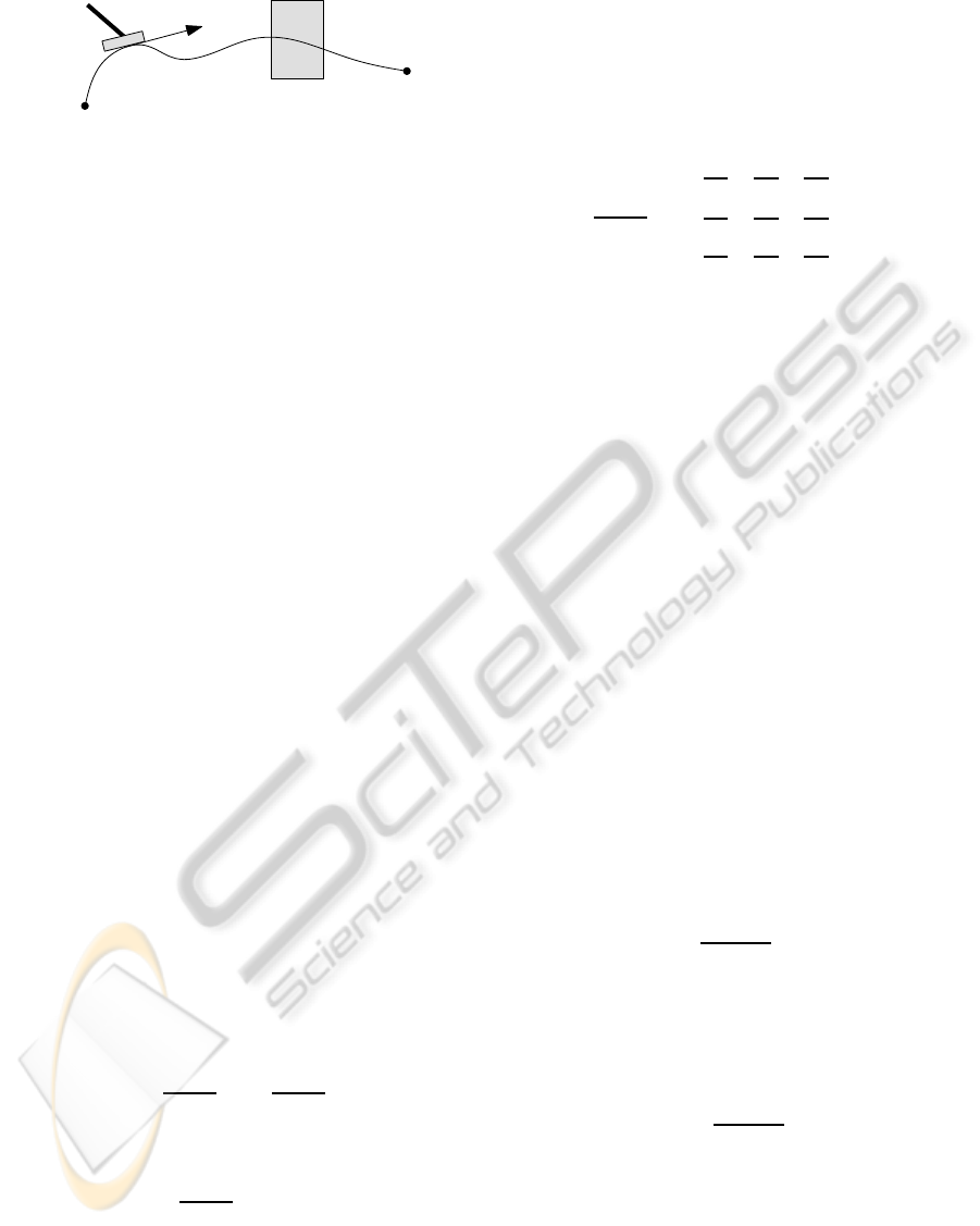
t
d
TCP path
Environment
Robot manipulator
Figure 2: Contact detection scenario.
surrounding. This is deliberate but must be handeled
in a manner as not to inflict damage. An algorithm
should be found to allow the robot an autonomous
(i.e. without the use of any extra sensors) detection
of such a collision.
After the detection, the robot should abort the ma-
neuver,report the incident to the sequence control and
hold its current position. Due to the limited band-
width of the pneumatic robot system, it is impossible
to avoid the peak in the contact force upon collision.
This has to be dealt with by choosing an appropri-
ate approaching velocity. After the impact, the robot
should not push against the surrounding.
The focus for this task is on two stiff clashing ob-
jects. (Haddadin et al., 2008) cover similar topics for
an electrically actuated robot with focus on safety.
4.1 Contact Force Estimation
In the contact case, the model multibody dynamics
Equation 3 does not hold any longer. There is a re-
maining term
Q
C
= M(q)
¨
q+ g(q,
˙
q) − Q
M
(q, p) (5)
that we interpret as a vector of external contact
torques acting on the joints. Deviations from the
model are also included there as well as measurement
errors. The velocities
˙
q and accelerations
¨
q are esti-
mated from the position sensor data.
As already mentioned,we are interested in the tool
contact scenario. Therefore, we use the relation for
the virtual work
δx
T
TCP
F
C
= δq
T
Q
C
(6)
and
δx
TCP
=
∂x
TCP
∂q
δq =
∂v
TCP
∂
˙
q
δq (7)
to get an equivalent tool center force estimation,
F
C
=
∂v
TCP
∂
˙
q
T
!
−1
Q
C
. (8)
The vector x
TCP
= [x y z]
T
contains the cartesian co-
ordinates of the tool center point, v
TCP
is the accord-
ing absolute translational speed. From the kinemat-
ics of the robot (Figure 1a), one can see that for a
reasonable tool geometry, joints 6 and 7 are insensi-
tive to contact forces because of the small lever arms.
More noise than information would be added, which
is why we did not include these joints in our algo-
rithm. Joints 3 and 5 are also excluded as they are
not actuated pneumatically. The Jacobian using the
velocities then reads
∂v
TCP
∂
˙
q
=
∂v
x
∂ ˙q
1
∂v
x
∂ ˙q
2
∂v
x
∂ ˙q
4
∂v
y
∂ ˙q
1
∂v
y
∂ ˙q
2
∂v
y
∂ ˙q
4
∂v
z
∂ ˙q
1
∂v
z
∂ ˙q
2
∂v
z
∂ ˙q
4
. (9)
4.2 Detection Criterion
We base the decision whether a tool impact occured
or not on the two basic ideas that in the contact case
1. the model Equation 3 changes to Equation 5 and
2. the controller (which was designed for free trajec-
tories) performance declines significantly result-
ing in a limited tracking accuracy.
The most simple way to utilize the first idea is to com-
pare the projected contact force
F
C
= F
C
· t
d
(10)
(t
d
is the tangent vector of the desired path, Figure 2)
to some threshold L in the form
C =
1 if F
C
> L
0 otherwise
(11)
where C = 1 means that contact is detected. Practi-
cally, it was impossible to find an L value resulting
in a low amount of false positives and negatives over
the desired workspace and speed range. This seems to
stem from the fact that the actuator model described
in Section 3.1 neglects too many effects (like drift and
hysteresis) to provide an accurate force measure.
To just detect the impact, we modified the criteron
to use
˙
F
C
(s) =
s
(s+ λ)
2
F
C
(s), (12)
an estimation of the force derivative with some addi-
tional low-pass filtering applied.
We also conducted experiments with the second
aforementiond idea. Including the controller error on
acceleration level in the form
D =
˙
F
C
(
¨
x
d
−
¨
x)
k
˙
xk
· t
d
(13)
showed the best results when again compared to some
constant level L. Index d denotes desired values. For
very low speeds (below 50 mm/s) the only robust de-
tection found was via the position error (x
d
−x) which
led to a rather big delay in the detection. In most
cases, this will render the detection useless as such
slow movements are typically used for delicate han-
dling scenarios.
ICINCO 2010 - 7th International Conference on Informatics in Control, Automation and Robotics
232
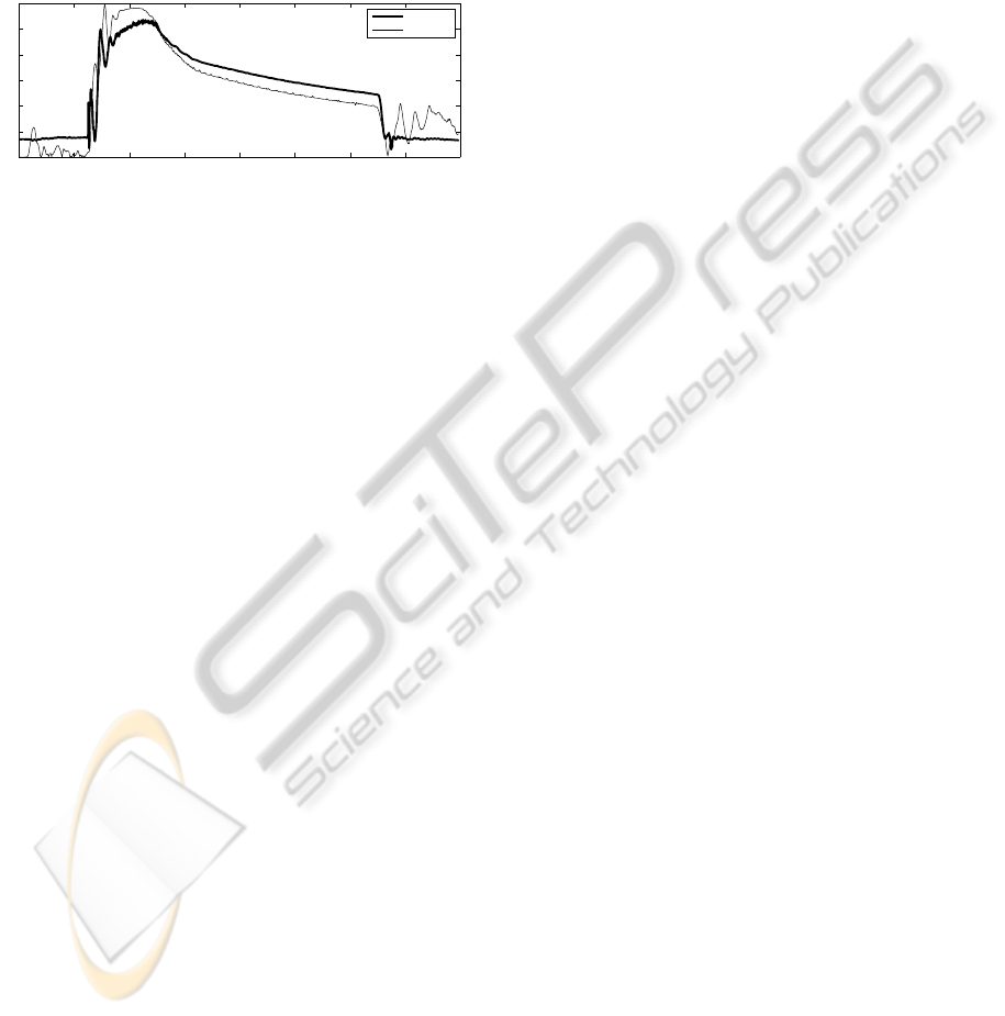
4.3 Measurement Results
We evaluated the detection by driving the manipula-
tor against a workbench at various speeds (50, 100,
150 and 250mm/s), in different directions (X+, Y+,
Z- – see Figure 1a – and mixed diagonal) and with
0.5 or 5 kg of payload mass. Each combination was
measured ten times.
0 2 4 6 8 10 12 14 16
0
10
20
30
40
50
60
measured
estimated
Figure 3: Example of estimated normal contact force in N
over time in s – compared to external sensor measurement.
Although the force characteristic (measured with
a three axis force sensor) varied over the different
scenarios, the detection was successful for nearly all
cases without adapting the threshold. Most problem-
atic was the combination of low speed and small pay-
load. Here we found at the same time false negatives
(5 for X+) and positives (3 for Y+). Other than that,
only one detection of over 300 failed.
The contact force – excluding impact peaks – al-
ways stayed below 20 N (and mostly below 10 N for
speeds below 150mm/s).
5 SHOW-DO PROGRAMMING
In guidance mode, a human can grasp the robot and
move it freely through the workspace. The robot is
still supported by the torques resulting from the model
in Equation 3 but any additional effort from the con-
troller is limited to very low values. Due to the soft
joints, one can interact with the robot along the com-
plete structure.
The guidance mode can be used to quickly move
the robot out of the way, to interactively teach posi-
tions or to record complete continuous path segments.
In our showcase we used a handle with two buttons,
mounted on the lower arm of the robot, to let the user
teach complete pick and place applications – similar
to a macro recorder known from personal computer
software. Tool actions trigger special behaviour – for
example the ”pick” macro at execution time moves
the manipulator in tool direction until it touches the
workpiece and does not solely rely on the recorded
position information.
The interaction with the robot proved to be intu-
itive and all kinds of people were quickly able to per-
form programming tasks.
6 CONCLUSIONS
In this paper we show how to use models of the me-
chanical system and the actuators of a pneumatically
drivenrobot for interaction with the environment. The
illustrated approach worked well when the human op-
erator compensated the remaining model uncertain-
ties. The completely autonomous interaction also
showed good results for the simple case of contact de-
tection.
A first effort to employ the presented interaction
possibilities for more intuitive programming led to
promising feedback from users.
ACKNOWLEDGEMENTS
The authors gratefully acknowledge the Austrian
Center for Competence in Mechatronics (ACCM) for
their support.
REFERENCES
Bicchi, A. and Tonietti, G. (2004). Fast and ”soft-arm” tac-
tics [robot arm design]. Robotics & Automation Mag-
azine, IEEE, 11(2):22–33.
Bremer, H. (2008). Elastic Multibody Dynamics: A Direct
Ritz Approach, chapter 4: Rigid Multibody Systems,
pages 59–113. Springer-Verlag GmbH.
Clark, D. R. and Lehto, M. R. (1999). Handbook of Indus-
trial Robotics, chapter 36: Reliability, Maintenance
and Safety of Robots, pages 717–754. John Wiley &
Sons, 2 edition.
Daerden, F. and Lefeber, D. (2002). Pneumatic artificial
muscles: Actuators for robotics and automation. Eu-
ropean journal of mechanical and environmental en-
gineering, 47:11–21.
Haddadin, S., Albu-Sch¨affer, A., De Luca, A., and
Hirzinger, G. (2008). Collision detection and reaction:
A contribution to safe physical human-robot interac-
tion. In Intelligent Robots and Systems, 2008. IROS
2008. IEEE/RSJ International Conference on, pages
3356–3363.
Hesse, S. (2003). The Fluidic Muscle in Application. Festo
AG & Co.KG.
Van Damme, M., Daerden, F., and Lefeber, D. (2005). A
pneumatic manipulator used in direct contact with an
operator. In Proceedings of the 2005 IEEE Interna-
tional Conference on Robotics and Automation.
INTERACTION OF A FLEXIBLE ROBOT WITH ITS ENVIRONMENT
233
