
A LEGACY SYSTEMS USE CASE RECOVERY METHOD
Philippe Dugerdil and Sebastien Jossi
HEG, University of Applied Sciences of Western Switzerland, 7 route de Drize CH-1227, Geneva, Switzerland
Keywords: Reverse Specification, Dynamic Analysis, Static Analysis, Execution Trace, Branch Condition Analysis.
Abstract: During the development of a legacy system reverse engineering method we developed a technique to help
with the recovery of the system’s use-cases. In fact, our reverse-engineering method starts with the re-
documentation of the system’s use-case by observing its actual users. But these use-cases are never
complete and accurate. In particular, the many alternative flows are often overlooked by the users. This
paper presents our use-case recovery methodology as well as the techniques we implemented to identify all
the flows of the legacy system’s use-case. Starting from an initial use-case based on the observation of the
users, we gather the corresponding execution trace by running the system according to this use-case. The
analysis of this execution trace coupled with a static analysis of the source code lets us find the possible
alternative execution paths of the system. The execution conditions for these paths are analyzed to establish
the link to the use-case level. This lets us synthesize alternative flows for the use-case. Next we run the
system again following these alternative flows to uncover possible new alternative paths, until one
converges to a stable use-case model.
1 INTRODUCTION
Generally, legacy systems documentation is at best
obsolete and at worse non-existent. Often, the
developers are not available anymore to provide the
maintainers with information on these systems. In
such situations the only people that still have a good
perspective on the system are its users. In fact they
are usually well aware of the business context and
business relevance of the programs. In short, their
interactions with the system represent instances of
relevant use-case.
The iterative and incremental reverse-
engineering technique we developed starts from the
recovery of the use-cases of the system. Then, by
incrementally rebuilding the analysis models, we are
able to re-create the traceability links between the
business functions and the source code of the
system. In summary, this reverse-engineering
method works through the following steps:
1. Re-document the system use-cases;
2. Design the Unified Process’ robustness
(analysis) diagrams associated to these use-cases
(Jacobson et al. 1999);
3. Execute the system according to the use-cases
and record of the execution trace;
4. Analyze the execution trace and identify the
classes involved in the trace;
5. Map the classes in the trace to the stereotypes of
the robustness diagram.
6. Re-document the architecture of the system by
clustering the classes based on their role in the
implementation of the use-case.
The efficiency of this method has successfully
been tested on 2 large systems (Dugerdil&Jossi
2008, Dugerdil&Jossi 2007). Since our approach
rests fundamentally on the recovered use-cases, their
quality and completeness are fundamental to the
performance of our reverse-engineering method.
However as we rely on system users to recover the
use-cases, the latter are never complete and accurate
especially regarding the alternative flows. Therefore
we developed a technique to recover complete use-
cases from the rough one given by the users.
The topic of this paper is to present our use-case
recovery approach. In contrast with other published
use-case recovering techniques based on the analysis
of the source code only (see for example (Li et al.
2007)) our approach rests on a first “draft” of the
use-case provided by users. This version is later
completed by analyzing the behavior of the program
as well as the source code of the classes involved in
the implementation of the use-case.
This position paper presents work in progress. It
is structured as follows. Section 2 discusses the
problem of recovering meaningful, i.e. relevant, use
232
Dugerdil P. and Jossi S. (2010).
A LEGACY SYSTEMS USE CASE RECOVERY METHOD.
In Proceedings of the 5th International Conference on Software and Data Technologies, pages 232-237
DOI: 10.5220/0003038602320237
Copyright
c
SciTePress
case in a given domain. Section 3 presents the use-
case recovery process and section 4 gives some hints
on the implementation technique. Section 5
discusses the related work. Section 6 concludes that
paper and presents future work.
2 RECOVERING RELEVANT
USE-CASES
According to (Leffingwell&Widrig 2003) “A use
case describes sequences of actions a system
performs that yield an observable result of value to a
particular actor”. Furthermore, “It (the use-case)
focuses on the value that the customer wants from the
system, not on how we subdivide and structure the
functionality within the system” (Bittner 2001).
Therefore, when trying to reverse-engineer the use-
cases from a legacy system, the goal is not to
generate any arbitrary set of statements, but to
actually recover a relevant one. Since software
specification lies at the boundary between business
and engineering (i.e. expressing functional requests
based on business justifications), the recovered use-
cases must be relevant to, and consistent with, the
business tasks of the users. However in the vast
majority of situation, if not all, the software source
code does not contain any substantial structured
business information to justify the software in
business terms. In other words the business relevance
of a given piece of code is not to be found in the
source code itself but lies outside the code (in the
head of the software analyst). This situation bears
some similarity to the linguistic domain where it is
well known that the understanding of a text requires
pre-existing knowledge of the domain (Roche 2006).
Therefore, it is clear that any use-case recovery
technique that is based on the analysis of the source
code only is bound to fail. In particular the structure
of the use-case (business level) is very loosely linked
to the structure of the software (technical level)
implementing it. Of course, both structures are not
completely uncorrelated, but the correlation is much
too weak to link the technical structure to the use-
case structure. Again, this is because the software
engineering and technical principles that lead to the
program structure are orthogonal to the business
requirements. In particular, the structure of the code
is driven by quality attributes considerations like
maintainability or performance (Bass et al. 2003).
However, since the actual users of the system
have a good perspective on the business relevance of
the system, they are able to execute scenarios that are
relevant to the business. But we know that the latter
are not complete and accurate enough to be
considered good use-cases. We will therefore
complete them by selectively searching the source
code for variants of the scenario and then abstracting
the information to generate complete relevant use-
cases. To illustrate this technique, we call the initial
scenario the “backbone” of the use-case, to which we
incrementally attach extra information that we obtain
from searching the source code.
3 USE-CASE RECOVERY
PROCESS
First, the legacy system’s source code is
instrumented to generate an execution trace for any
scenario performed on the system. The instrumented
source code is then recompiled and installed on the
machine. Next, the scenario we recovered from the
user is played on the machine and the execution
trace is recorded. The latter then contains the
sequence of methods or functions executed while
performing the scenario. The format of the execution
trace is quite classical. Each method call, called an
“event”, has the following form:
[packageName][className][methodSignature][processId]
After having recorded the execution trace it is
analyzed to identify the methods executed. For each
method called, we look for conditional statements in
its source code. When such a statement is found, the
non-executed path represents a candidate for a
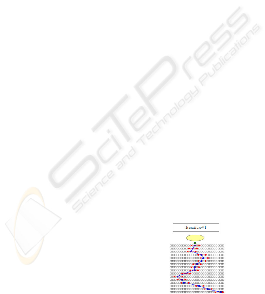
variant of the use-case. This is illustrated in Fig. 1.
The small squares symbolize the program statements
and the central broken line represents the sequence
of statements executions for the “backbone”. The
small horizontal arrows represent the search for
variants around the “backbone” statements. The
purpose is to find the statements that could possibly
be called but haven’t been. These may represent
extra steps in the main flow or steps of the
alternative flows.
Figure 1: Iteration 1 performed on the “backbone”.
A LEGACY SYSTEMS USE CASE RECOVERY METHOD
233
The next task is to link the conditional statements
in the code to the user interfaces involved in the
“backbone” scenario, to know if the alternative
statements could possibly be executed by
performing some extra user interactions. In other
words, we must answer the following question:
could the boolean condition of the branching
statement be changed by imputing some specific
value or selecting some extra option at the user
interface level? If yes, the corresponding user
interaction is added as an extra step to the scenario.
Then the users are asked to validate the relevance of
the new scenario (previous one + new interaction). If
it is OK, the new scenario is played and a new
execution trace is generated. This process is repeated
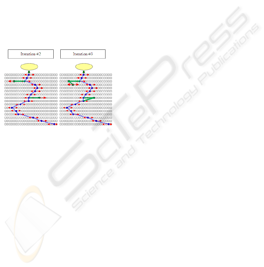
until we reach a stable set of variants. This
incremental process is symbolized in figure 2.
Figure 2: Extra iterations performed on the “backbone”.
The new segments of the broken line represent
variant of the behavior of the system obtained via
the new user interaction determined by the static
analysis of the source code. In summary our
technique uses dynamic (i.e. execution trace) and
static (i.e. source code) analysis.
4 USE-CASE RECOVERY
TECHNIQUE
The implementation of our approach requires two
sources of information:
1. The execution trace of the scenarios;
2. The source code of the classes involved in
execution trace.
The whole process is illustrated in figure 3. First,
a rough use-case is rebuilt from the scenario
recovered from the users. Next the scenario is
executed on the instrumented system to get the
execution trace. The latter is then recorded and the
methods corresponding to each event is analyzed. If a
conditional statement is found in that code, this could
lead to an alternative behavior (
C6 t() in the
example) depending on the boolean condition. Then
the system tries to link this boolean condition (the
k
variable in the example) to the user interface of the
use-case. This is to check if some user interaction
could lead to a change in the boolean value of k. If
yes, then the alternative path (
C6 t() instead of C5
t()
) will be taken if this action is taken. To identify
the non-executed conditional statements in the code,
we rest on the analysis of the execution trace again
which is represented by the corresponding call tree.
Starting from a node that represents an event, we
check if the method that could conditionally be
executed is a child node of the current node in the
class tree. If not, then this represents a potential
alternative path and the source code is backward
sliced from the condition to uncover alternative
scenarios. Backward slicing is a technique to identify
all the statements in a program that could possibly
influence the value of some variable at a specific step
in the program (called the slicing criteria
(Binkley&Gallagher 1996)). Therefore, if a user
interaction through a control of the GUI could
change the value of a condition in the code, this
means that the statements associated to the control
must be included in the backward slide from the
conditional statement.
In summary the algorithm to find alternatives is the
following:
For each event in the trace
Retrieve the conditional statements in its code.
For each conditional statement
If the corresponding method is not a child of
the current node
Then
1.Backward slice the source code of the
program from the condition.
2.Analyze the slice to find if there are
statements belonging of the scenario’s
GUI.
3.Check if the GUI statements are associated
to some user selectable control.
4.Deduce the value to be inputted/selected
through the GUI to change the condition.
endIf
endFor
endFor
Technically, the source code of each event
(method) is parsed to generate its AST. The latter is
then analyzed using the « Visitor » design pattern
(Gamma et al. 1995). Both the AST generator and its
parser have been kindly shared by Júlio Vilmar
Gesser (Java 1.5 Parser and AST 2010).
ICSOFT 2010 - 5th International Conference on Software and Data Technologies
234
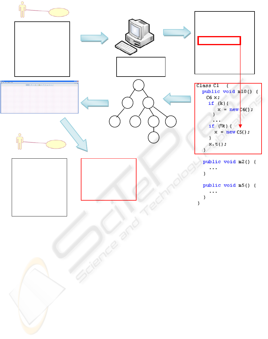
Figure 3: Workflow of our method.
In most of the cases, the identification of the
method that is called in the trace is easy. However in
some cases the calls are ambiguous.
Let us see a simple example where
method1()
would be declared in Class1:
void method1() {
…
if(condition1) then x.method2();
if(condition2) then y.method2();
…}
In the execution trace we may get the following
sequence of events:
package1 Class1 method1()[1]
package2 Class7 method2()[1]
We know from the source code of method1() that
method2() might be called. But what is the exact
code executed in this case? In other words was
conditon1 or condition2 true? The answer will be
known by identifying the class of the object
referenced by x and y. Now the problem comes back
to finding these classes. This represents a major
issue. The technique is to compute the type of the
variable at the location of the conditional statement.
Of course, the analysis of the static type (class) of
the variable is not enough since the program could
assign an instance of a subclass to the variable. We
must therefore analyze the assignments statements to
the corresponding variables up to the conditional
statement. The solution is to launch yet another
Visitor (Gamma et al. 1995) to identify these
assignment statements. While the visitor searches
the code a dynamic type table is filled with the
conditions that correspond to each of the assignment
statements. Figure 4 presents the UML model of
such a table. This table helps us to relate the
conditions with each other in the code. In fact all the
alternative paths in the program are not independent.
Many paths will indeed be controlled by the same
condition or by a combination of known conditions.
+
Use Case X
Main flow
1)---------------------
2)---------------------
3)---------------------
4)---------------------
5)---------------------
Use Case X
Main flow
1)---------------------
2)---------------------
3)---------------------
4)---------------------
5)---------------------
-----------------------
Alternative flow
2a)-------------------
2a1)------------------
2a2)------------------
2a3)------------------
Execution Trace
P1 C3 m5() [1]
P1 C1 m10() [1]
P1 C5 t() [1]
P1 C1 m1() [1]
P1 C8 m9() [1]
Abstract Syntax
Tree (AST)
A LEGACY SYSTEMS USE CASE RECOVERY METHOD
235
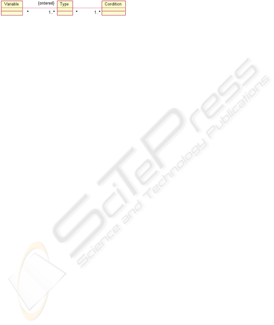
The dynamic type table is then used to determine
truly independent paths in the program.
Figure 4: Dynamic type table.
When the type of the variables is known, we can
disambiguate the call observed in the trace and
identify the alternative scenarios. So far we
implemented the first part of the method, up to the
identification of the conditional statements that
could lead to alternatives. The next step will be to
backward slice the code to find the alternative flow
steps. The conditional statement identification
mechanism has been applied on the “FastUML”
(FastUML 2010) open source software. First we
instrumented its source code and defined a rough use
case (“backbone”). Then we played it on the system,
got an execution trace and performed our trace
analysis technique to find alternative paths. This
allowed uncovering 10 alternative calls from the
“backbone”.
5 RELATED WORK
A technique that bears some similarity with ours is
the work of (Ko & Myers 2008). Their debugging
application technique is based on dynamic and static
analysis and generates a precise call graph by using
every invocation found in the source code. This tool
allows the user to run buggy functions to uncover the
code associated to that function. Moreover, the
application dynamically generates questions that the
user can ask about program behavior. But this work
does not aim at recovering the use-cases of the
system. On the topic of reverse specifications, (Li at
al. 2007) proposed a technique to rebuild a complete
use case diagram based on dynamic information
(execution trace). They start by retrieving methods
that are located at the root of the call trees build from
the execution trace. These root methods are supposed
to represent the root of the scenarios. But we think
this to represent too strong an hypothesis, because it
deeply depends on the structure of the code. For
instance a root method could implement a menu
while the real business function would be located at a
much deeper level. In order to rebuild the software
behavior model based on execution traces,
researchers from the University of Ottawa worked by
filtering out utility components to keep only high
level elements (Hamou-Lhadj et al. 2005). Their
algorithm seems to produce good results, but their
technique is not adapted to our problem. Since they
are no guided by any business level information,
there is no guarantee that the retrieved statement
correspond to a relevant use-case. (El-Ramly et al.
2002) have developed a method to recover the use-
cases from dynamic information but again they work
the other way around by rebuilding the use-case
without the guidance of some user-level information.
Therefore there is no guarantee that the recovered
use-case would be relevant to the users. (Di
Lucca&Fasolino&De Carlini 2000) also use a
dynamic technique to recover the use cases. However
the problem here is the very definition of what a use-
case means (Leffingwell& Widrig 2003). In fact,
their technique is limited to recording the statements
between an input event and the first output event.
Therefore this cannot be considered a real use-case
since it is limited to analyzing a single feature of the
system, not a whole scenario of business value.
Finally, (Qin et al.2003) presented a method to
retrieve the use-cases of a system by building a
branch-reserving call graph. From this graph they
could rebuild sequences of user interactions by hand.
Although they claim to be able to retrieve plain use-
cases, the real question is: what is the business value
of the recovered use-cases? Again the key idea is not
to retrieve any arbitrary sequence of user interactions
but one that represents a real business task. As far as
slicing tools are concerned, we explored a few open
source tools. (JSlice 2009) seemed at first to be a
good candidate. However it cannot work on user
defined trace execution format. It must use its own
trace format. Therefore we cannot insert it easily in
our framework. But the key problem is due to its
JVM which is not a standard one but (Kaffee 2009).
The latter lacks compatibility with current versions of
Java. The (Wisconsin Program-Slicing Project 2009)
released an open source slicing tool. But the latter is
designed for C language only. GrammaTech markets
two slicing tools. The first one, (Code Surfer 2009),
is actually the commercial version of Wisconsin
Program Slicing Project. The second, (Code Sonar
2009), is also designed for C type languages. Finally,
the best candidate we found is (Indus 2009)0
developed at Kansas State Univ. It is designed for
Java code. This is the one we are concentrating on
presently.
6 CONCLUSIONS AND FUTURE
WORK
The fundamental claim of this paper is that it is not
possible to recover relevant use-cases of a system by
ICSOFT 2010 - 5th International Conference on Software and Data Technologies
236

simply analyzing the source code of the system. This
is because use-cases represent system usage that
must bring a result of business value to the user
(Leffingwell&Widrig 2003) (Bittner 2001). Hence,
any set of user interactions with the machine does
not represent a use case. It is just a set of user
interactions, nothing more. For such a set of
interaction to represent a true use-case, all
interactions must be targeted at providing the user
some result of business value. This business value
lies outside of the system. It is in the head of the user
(and in some rare cases in the documented business
processes involving the IT system). Therefore, our
key idea to recover business-relevant use-case is
actually to start from an initial user-defined scenario
and to incrementally enhance this scenario to
converge to a complete use-case. Since we start form
a scenario of business value, the value of the use-
case resulting from our process is guaranteed. We
called the initial scenario the “backbone”, since this
is a relevant scenario of business value to the user
that will later be completed. To perform this
completion, we proposed to use dynamic as well as
static analysis techniques. The first one let us find
the code that is executed while running a scenario
(i.e. the execution trace). Then the executed code
(the set of events) is searched for alternative
execution paths. Once such a path is found, our
technique tries to link the condition of its execution
to the scenario’s GUI. This is to check if some
alternative user interaction could possibly lead to the
execution of the alternative path. If such a link is
found the alternative interaction is presented to the
user for validation. If it is validated, the system is
run again with the alternative interaction and the
corresponding executed code analyzed. This process
is repeated until the scenarios converge to a
consistent use-case. As of today, the first part of the
use-case recovery method is implemented, up to the
identification of alternative execution paths. The
next step is to use a backward slicing tool to retrieve
the corresponding user interactions. This is the work
are concentrating on presently. We hope to complete
the work by the end of the summer 2010.
ACKNOWLEDGEMENTS
This work has been done with the support of HESSO
Grant N°24245 from the Swiss Confederation,
which is gratefully acknowledged.
REFERENCES
Bass L., Clements P., Kazman R. 2003. Software
Architecture in Practice, 2nd edition. Adison-Wesley
Inc.
Jacobson I., Booch G., Rumbaugh J. 1999. The Unified
Software Development Process. Addison-Wesley
Professional.
Roche Ch. 2006. How Words Map Concepts . Proc. 10
th
IEEE EDOCW.
Binkley D. W., Gallagher K. B. 1996. Program Slicing. in:
Advances in Computers, vol 43, Academic Press.
Gamma E., Helm R., Johnson R., Vlissides J. 1005.
Design Patterns. Elements of Reusable Object
Oriented Software. Addison-Wesley Inc.
Ko A., Myers B., 2008. Debugging reinvented: asking and
answering why and why not questions about program
behavior, Proc. IEEE ICSE.
Li Q., Hu S., Chen P., Wu L., Chen W. 2007. Discovering
and Mining Use Case Model in Reverse Engineering,
Proc. IEEE FSKD.
Hamou-Lhadj A., Braun E., Amyot D., Lethbridge T.
2005. Recovering Behavioral Design Models from
Execution Traces. Proc IEEE CSMR.
El-Ramly M., Stroulia E., Sorenson P. 2002. Mining
System-User Interaction Traces for Use Case Models.
Proc IEEE IWPC.
Di Lucca G. A., Fasolino A. R., De Carlini U. 2000.
Recovering Use Case models from Object-Oriented
Code: a Thread-based Approach. Proc IEEE WCRE
Qin T., Zhang L., Zhou Z., Hao D., Sun J. 2003.
Discovering Use Cases from Source Code using the
Branch-Reserving Call Graph. Proc. IEEE APSEC.
Wisconsin Program-Slicing Project. 2009, www.cs.wisc.
edu/ wpis/html/
JSlice 2009, jslice.sourceforge.net/
Kaffee 2009, www.kaffe.org/
Indus 2009 indus.projects.cis.ksu.edu/
CodeSonar 2009. www.grammatech.com/products/code
sonar/ overview.html
CodeSurfer 2009. www.grammatech.com/products/code
surfer/ overview.html
Leffingwell D, Widrig D. 2003 Managing software
requirements, Addison Wesley.
Bittner K. 2001. Why use cases are not “functions” - The
Rational Edge.
Dugerdil Ph., Jossi S. 2008. Empirical Assessment of
Execution Trace Segmentation in Reverse
Engineering. Proc ICSOFT
Dugerdil Ph., Jossi S. 2007 Reverse-Engineering of an
Industrial Software Using The Unified Process: An
Experiment. Proc IASTED SEA.
Javacc 2010 https://javacc.dev.java.net/
Java 1.5 Parser and AST 2010 javacc.dev.java.net/servlets/
ProjectDocumentView?documentID=44514&showInf
o=true
FastUML 2010 - sourceforge.net/projects/fastuml/
A LEGACY SYSTEMS USE CASE RECOVERY METHOD
237
