
AXISYMMETRIC AND ASYMMETRIC BEHAVIORS
OF A RED BLOOD CELL IN CAPILLARIES
Ting Ye and Hua Li
School of Mechanical and Aerospace Engineering, Nanyang Technological University, 50 Nanyang Avenue
Singapore 639798, Republic of Singapore
Keywords: Red blood cell, Membrane force, Tank treading, Capillary flow, Computational biomechanics.
Abstract: The axisymmetric and asymmetric behaviours of a red blood cell (RBC) in capillaries are investigated
numerically by developing a two-fluid model, in which the membrane force is considered to describe the
RBC deformation. The quantitative validations with the experimental and theoretical results are provided,
and good agreements are found in the deformation index and deformed RBC shapes. The present results
show that the RBC experiences the axisymmetric motion if the membrane force is balanced between the
RBC cusps, otherwise the asymmetric motion occurs. The characteristic parachute shape of deformed RBC
is observed in the axisymmetric motion, while the tank-treading motion of RBC membrane is generated in
the asymmetric motion. As the capillary diameter increases, the decrease in RBC length is accompanied by
an increase in RBC width.
1 INTRODUCTION
Red blood cells (RBCs) play an essential role in
delivering oxygen to the body tissues via blood flow
through capillaries in all vertebrates and some
invertebrates. In human, a healthy mature RBC is
biconcave disk 8 µm in diameter and 2 µm in
thickness, which consists of cytoplasm enclosed by a
thin membrane (Evans and Fung, 1972). The RBC
membrane can experience stretching and bending
deformations subject to the blood flow, thereby it is
mainly responsible for the mechanical and
rheological behaviours of the RBC. It is well known
that RBCs are involved in many diseases, such as
the sickle-cell anemia resulted from the RBC
abnormality, and the capillary blockage due to the
RBC fragments. Therefore, it is of great importance
to study the behaviours of a RBC in capillaries for
revealing the mechanism of RBC deformation and
providing the insight into the RBC fighting against
relevant diseases.
Generally, a RBC in a capillary experiences an
axisymmetric motion, where the RBC is
axisymmetric with respect to the central axis of the
capillary due to the very small diameter (Secomb,
1987). In this motion, the RBC gradually deforms
from a biconcave shape into a parachute one. This
parachute shape is the characteristics of a RBC in a
capillary, which guarantes the RBC traversing
through various capillaries successfully, including
the smaller capillaries compared with the
undeformed RBC. The previously published works
(Secomb, 1987, Tsukada et al., 2001, Jeong et al.,
2006, Tomaiuolo et al., 2009) demonstrate that the
deformability of RBC in capillaries depends on the
RBC velocity and capillary diameter largely. With
increasing the RBC velocity or decreasing the
capillary diameter, the RBC width becomes
narrower accompanied by an increase of the length.
Thus, even though the capillary is very narrow, the
RBC may be squeezed through it successfully.
Instead of an individual RBC, Pozrikidis (2005)
numerically analyzed the axisymmetric motion of a
file of RBCs through capillaries using a boundary
integral method, and also examined the effects of the
cell spacing and capillary radius. However, if the
capillary diameter is quite large, the RBC shape
cannot be assumed to be axisymmetric any more
with respect to the central axis of the capillary. As a
result, the RBC will undergo an asymmetric motion.
Secomb and Skalak (1982) studied the asymmetric
motion of a RBC in a two-dimensional capillary
based on the lubrication method. They pointed out
that the tank-treading motion of the RBC membrane
usually accompies this motion. In other words, the
RBC membrane always rotates around the
97
Ye T. and Li H..
AXISYMMETRIC AND ASYMMETRIC BEHAVIORS OF A RED BLOOD CELL IN CAPILLARIES.
DOI: 10.5220/0003105700970102
In Proceedings of the International Conference on Biomedical Electronics and Devices (BIODEVICES-2011), pages 97-102
ISBN: 978-989-8425-37-9
Copyright
c
2011 SCITEPRESS (Science and Technology Publications, Lda.)

cytoplasm in the asymmetric motion, like the tank
treading. In order to understand the tank-treading
motion, Sugihara-Seki and Skalak (1988)
investigated the asymmetric flow of a file and two
files RBCs using the finite element method, in which
each RBC is assumed as a rigid cylinder post and
not located at the centerline of capillary. Although a
certain progress has been achieved so far, the
detailed knowledge of the flow behaviors of a RBC
in capillaries is still of interest, especially for the
asymmetric motion of RBC.
In the present work, a two-fluid system is
developed to model the flow characteristics of a
RBC in capillaries, in which the mechanical
behavior of the RBC membrane is taken into
consideration. Subsequently, validations of this
system are carried out by comparing with the
experimental and theoretical results. Finally, the
axisymmetric behaviors of a RBC in capillaries are
simulated systematically on the basis of the two-
fluid system. Apart from that, the asymmetric
motion of the RBC in the capillary is also analyzed
in detailed, as well as the effect of the capillary
diameter.
2 MODELS AND METHODS
Figure 1: 2D schematic diagram of a RBC in a capillary
subject to the plasma flow with parabolic velocity profile.
The 2D schematic diagram of a RBC in a capillary is
provided in Figure 1, in which a plasma flow with a
parabolic velocity profile passes through the
capillary along the x direction. The 2D RBC with
zero velocity is put in the plasma flow, whose shape
is expressed as the parametric form (Evans and Fung,
1972),
24
0012
0
cos ( sin sin ),
sin ,
xx r c c c
yy r
θ
θθ
θ
=+ + +
=+
⎧
⎨
⎩
(1)
where (x
0
, y
0
) is the RBC centre, r the maximum
radius, and θ the polar angular in the range [0, 2π].
The three coefficients c
0
, c
1
and c
2
are usually taken
as 0.1035, 1.0013 and −0.5614, respectively. Due to
the stress of the plasma flow, the RBC will move
and deform.
2.1 Governing Equations
A two-fluid system is developed here to describe the
fluid states of the RBC and plasma. The material
properties of fluids inside and outside the RBC are
different, such as density and viscosity. By treating
these two fluids as a single fluid with variable
material properties, the incompressible Navier-
Stokes equations are used over the whole domain to
describe the motion of the single fluid, written as
0,
() [( )],
T
p
t
ρ
ρμ
∇⋅ =
∂
+∇⋅ =−∇ +∇⋅ ∇ +∇ +
∂
⎧
⎪
⎨
⎪
⎩
u
u
uu u u F
(2)
where u is the velocity vector, ρ and µ are the
density and viscosity of fluid, t is the time, p is the
pressure. The membrane force F reflects the
interaction between the RBC and plasma as the
result of the membrane deformation, given by
()
(,) ( ) ,
m
t
s
tds
δ
Γ
−=
∫
fxxF
(3)
where x and x
m
are the spatial variable and
membrane position of Γ(t), s is the membrane length,
δ(x) is the 2D Dirac delta function, and f(s, t) is the
membrane force strength.
The membrane force strength can be derived by
the shell model (Pozrikdis, 2003), in which the
membrane is treated as a thin shell with finite
thickness, allowed to undergo bending and
stretching deformations, expressed by
2
2
(,) ,
ddm dm
st
ds ds ds
τ
κκτ
⎛⎞
⎛⎞
=+−
⎜⎟
⎜⎟
⎝⎠
⎝⎠
f
+t n
(4)
where τ and m are the in-plane tension and bending
moment, t and n are the unit tangent and normal
vectors, and κ is the curvature of the membrane.
Introducing the constitutive equations, the in-plane
tension and bending moment are expressed as
S
E
τ
ε
=
and
0
(),
B
mE
κκ
= −
(5)
where E
S
and E
B
are the shear modulus and bending
stiffness, ε is the membrane strain, and κ
0
the resting
curvature of the membrane.
2.2 Numerical Methods
In numerical simulations, the computational domain
is discretized first by the staggered grid system.
Based on this grid system, the governing equations
are divided into three parts to be solved, namely
BIODEVICES 2011 - International Conference on Biomedical Electronics and Devices
98
calculating the membrane force, tracking the
membrane and solving the Navier-Stokes equations.
In order to calculate the membrane force, the
membrane is discretized by a set of Lagrangian
particles. Any two neighbouring Lagrangian
particles are connected by a straight line as a
membrane element. Thus, the strain and curvature of
each membrane element are obtained easily,
followed by the membrane force strength in Eq. (4)
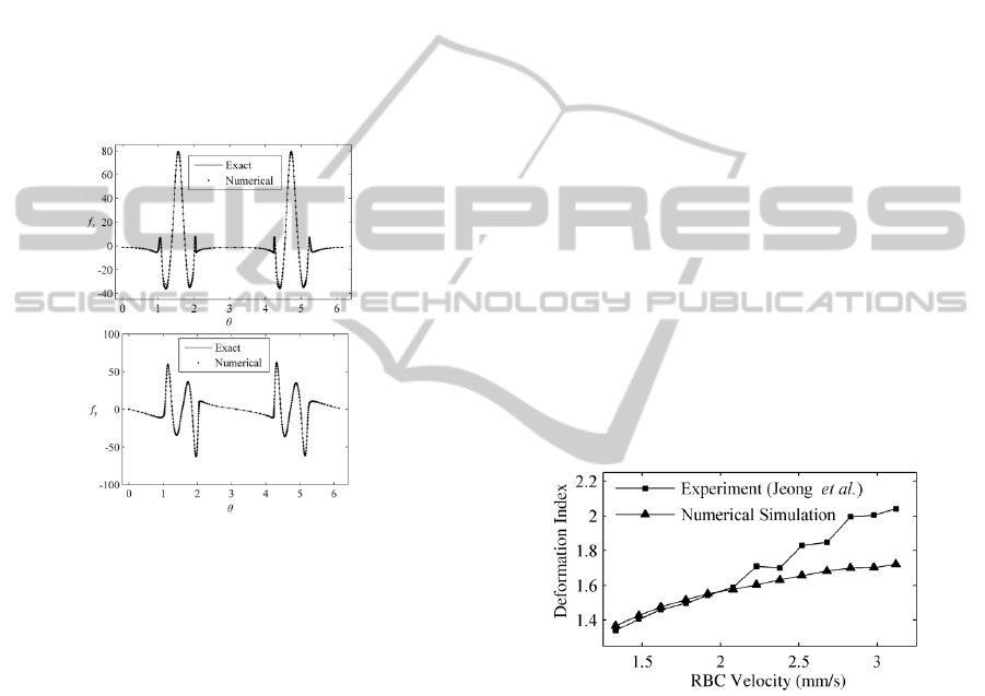
by the finite difference method. Figure 2 shows
comparisons of the membrane force strength at a
fixed state between the numerical and exact results,
in which good agreement is observed. After that, Eq.
(3) is approximated by the trapezoidal rule so that
the calculation of the membrane force is completed.
Figure 2: Comparisons of the membrane force strength
between the numerical and exact results. The top (a) and
bottom (
b) figures correspond to the non-dimensional x-
and
y-components of membrane force strength,
respectively.
The material properties inside and outside RBC
are different, such that the membrane needs tracking
to distinguish the RBC and plasma. Besides, the
membrane position should be provided for
calculating the membrane force by Eq. (3). For these
two purposes, the binary level set method (Lie et al.,
2006) is used to track the membrane, in which a
binary level set function is defined to distinguish the
plasma and RBC, and governed by a convection
function. By solving the convection function using
the WENO scheme (Shu, 1997), the membrane can
be tracked. However, the accuracy of tracking the
membrane is not good due to the numerical
dissipation. In order to overcome the disadvantage,
the Lagrangian particles scattered to calculate the
membrane force are used again to correct the binary
level set function.
Finally, a hybrid method coupled SIMPLER
(Patankar, 1981) and SIMPLEC (Van-Doormaal and
Raithby, 1984) is developed to solve the Navier-
Stokes equations, after the material properties of
fluid are updated. In this method, a relative accurate
pressure field is obtained first by the SIMPLER idea
as the initial iterative pressure, and then the velocity
field is computed according to the momentum
equations. Generally, this velocity field cannot
satisfy the continuity equation with the sufficient
accuracy. Hence, a velocity correction is provided
by the SIMPLEC idea as the second step, which is
derived by the continuity equation. These two steps
are repeated as an iterative process until both the
continuity and momentum equations converge. Thus,
the pressure and velocity fields are updated at the
current time step.
3 RESULTS AND DISCUSSION
3.1 Validation
In this section, the model is validated by comparing
the present numerical predictions with the
previously published experiment (Jeong et al., 2006,
Tomaiuolo et al., 2009) and theoretical (Secomb,
1987) results.
Figure 3: Comparison of the predicted deformation index
with the experimental result (Jeong
et al., 2006).
Jeong et al. (2006) investigated experimentally
the RBC deformation in the rat mesenteric
capillaries. In their work, the effects of the diameter
and length of capillary are examined, as well as the
RBC velocity on the deformation index, defined as
the ratio of the length to diameter of the deformed
RBC (Tsukada et al. 2001). Here, we focus on one
of them, the relationship between the deformation
index and the velocity of RBC in a capillary with the
diameter of 6.2 µm. The comparison between the
present numerical and experimental results is shown
in Figure 3, in which a good agreement is found in
the increasing trend of deformation index. The
AXISYMMETRIC AND ASYMMETRIC BEHAVIORS OF A RED BLOOD CELL IN CAPILLARIES
99
average deformation index of RBC in the capillary is
about 1.58 very closed to the value of 1.55 reported
by Jeong et al. (2006). However, the deformation
index is smaller than that of Jeong et al. (2006) at
the higher velocity, which can be explained that the
deformed RBC in the experiment is no longer
axisymmetric at the higher velocity.
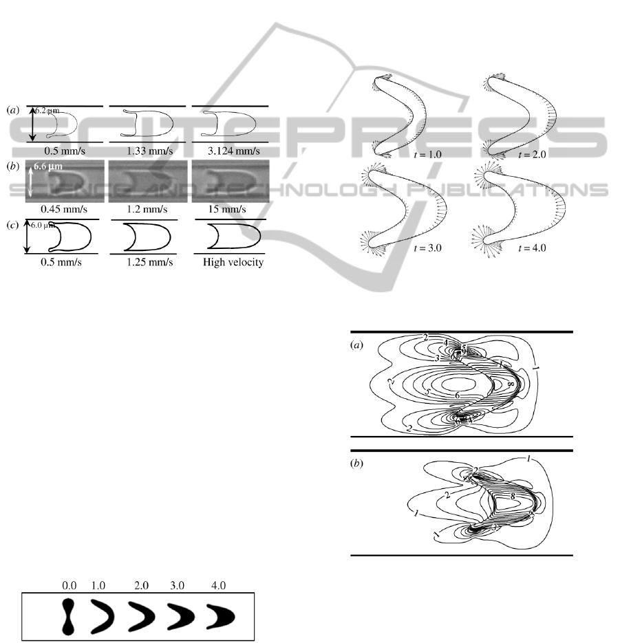
Furthermore, a comparison of the RBC shape at
the steady state is illustrated in Figure 4, in which
the experimental (Tomaiuolo et al., 2009) and
theoretical (Secomb, 1987) shapes are obtained in
the capillaries with diameters of 6.6 and 6.0 µm,
respectively. As expected, a good agreement is
provided in the deformed shapes, although there
exist slight differences resulted from the different
capillary diameter.
Figure 4: Comparison of the predicted RBC shape (a) with
the experimental (
b) (Tomaiuolo et al., 2009) and
theoretical results (
c) (Secomb, 1987).
3.2 Axisymmetric Motion of RBC
When the RBC shape is axisymmetric with respect
to the central axis of capillary, it will experience the
axisymmetric motion. Figure 5 shows the RBC
deformation behaviours in a capillary with the
diameter of 10 µm subjected to the maximum flow
velocity of 1.25 mm/s. At the initial state, a
biconcave RBC is located at the central axis of
capillary. In the presence of parabolic blood flow,
the RBC deforms gradually to a steady parachute
shape, convex in front (at leading surface) and
concave at the rear. Meanwhile, the RBC is
transported forward, and the RBC shape is always
axisymmetric.
Figure 5: RBC shapes in a capillary at different time,
where the number on the top of each snapshot indicates
the non-dimensional time
t.
The axisymmetric deformation behaviour is
attributed to the distribution of membrane force
strength, as shown in Figure 6. With increasing time,
the membrane force strength increases at the sharp
cusps and the leading surface, such that the
deformation at these parts also becomes larger and
larger. At the leading surface the membrane force is
generated mainly by the stretching deformation,
which makes the RBC outward bulge at the leading
surface. However, it is attributed to the bending
deformation largely at the sharp cusps, squeezing the
sharp cusps narrower and narrower continuously. As
a result, the RBC deforms to a steady parachute
shape from the initial biconcave shape.
Figure 6: Distribution of membrane force strength at
different time, where the number on the bottom right of
each snapshot indicates the non-dimensional time.
Figure 7: Distribution of the non-dimensional flow speed
for a RBC in the capillary. The top (
a) and bottom (b)
figures correspond to the non-dimensional time of 2.0 and
4.0, respectively.
Figure 7 illustrates the contour plots of non-
dimensional flow speed in ten levels from 0.0 to
0.25. It is found that the flow speed inside the RBC
is larger than that in the carrier fluid, such that the
BIODEVICES 2011 - International Conference on Biomedical Electronics and Devices
100

RBC becomes rounder and rounder. Furthermore,
the flow speed inside the RBC decreases with
increasing time. Once the flow speeds inside and
outside the RBC maintain equally each other, the
RBC will achieve a steady state.
3.3 Asymmetric Motion of RBC
Apart from the axisymmetric motion, the RBC also
undergoes an asymmetric motion if the RBC shape
is not axisymmetric with respect to the central axis
of the capillary. In this section, the asymmetric
motion of the RBC is investigated by locating the
RBC near the central axis of the capillary.
Figure 8 depicts the motion and deformation of
the RBC, whose centre is placed above and below
the central axis of the capillary at the initial state.
The leading surface of RBC bulges gradually, while
the rear becomes more concave to maintain the area
conservation. In addition, the RBC tilts
anticlockwise when the RBC centre at the initial
state is above the central axis, as shown in Figure
8(a). However, the opposite tilt orientation is
observed if the RBC centre is below the central axis,
as illustrated in Figure 8(b). The tilt behaviours are
resulted from the parabolic distribution of the flow
velocity, which makes the upper and lower parts of
RBC undergo the unbalanced velocities. As the RBC
tilts gradually, the RBC membrane also rotates
around the RBC interior continuously, as found by
the motion of the representative node (hollow circle)
in Figure 8. This phenomenon is well known as the
tank-treading motion of the membrane.
Figure 8: The asymmetric motion of a RBC in the
capillary, where the top (
a) and bottom (b) rows are
obtained by adjusting the RBC centre slightly above and
below the central axis of capillary at the initial state, and
the hollow circles refer to the motion of a fixed
representative node.
Figure 9 illustrates the distribution of membrane
force strength at the non-dimensional time of 3.0 for
the RBC centre above and below the central axis of
the capillary. It is found that the membrane force
strength is significantly large at the sharp cusps. The
sharper the cusp is, the larger the membrane force
strength is. This is because that the bending moment
plays a dominant role in the membrane part with the
large curvature. For example, the curvature at the
lower cusp is larger than that at the upper cusp of
each deformed RBC in Figure 9. Hence, the
membrane force strength is also larger at the lower
cusp. The unbalanced membrane force strength at
the upper and lower cusps is one of the
characteristics of the RBC asymmetric motion,
which is different from the RBC axisymmetric
motion.
Figure 9: Distribution of the membrane force strength at
the non-dimensional time of 3.0 for the RBC centre above
(
a) and below (b) the central axis of the capillary.
3.4 Effect of Capillary Diameter
In general, capillary diameter is about 6-10 µm,
which has a significant effect on the RBC
deformation except the RBC velocity. In this section,
the effect of capillary diameter is examined by
simulating the motion and deformation of a RBC in
the capillaries with diameters of 6.2, 8.0, 10 and 12
µm, respectively. With consideration of the diameter
of biconcave RBC, an elliptical RBC with the same
area of the biconcave RBC is treated as the initial
shape in the capillary of 6.2 µm.
Figure 10: RBC shapes in the capillaries with the different
diameter at the different time. The numbers on the top of
figure indicate the non-dimensional time.
AXISYMMETRIC AND ASYMMETRIC BEHAVIORS OF A RED BLOOD CELL IN CAPILLARIES
101

Figure 10 shows the motion and deformation of a
RBC in the different capillaries. As the capillary
diameter decreases, the increase in RBC length is
accompanied by a decrease in RBC width.
Consequently, the deformation index increases with
decreasing the capillary diameter. In other words,
the RBC has to be elongated more when it passes
through a smaller capillary, thereby leading to the
increasing trend of the deformation index. This
increasing behaviour is attributed to the shear stress
of the fluid flow. At a given flow velocity, the shear
stress increases with decreasing the capillary
diameter, such that the RBC is stretched more
obviously at the smaller capillary. In addition, the
RBC in the large capillary moves further than that in
the small capillary, as indicated in Figure 10(b), (c)
and (d). This is because that the RBC is more
centralized on the central axis of the capillary when
the capillary diameter is larger. At the end, the RBC
shape deforms asymmetrically in a small capillary as
shown in Figure 10 (a), especially at the non-
dimensional time of 4.0. The reason for the
asymmetric behaviour is that the shear stress acting
on the RBC membrane is more unbalanced if the
RBC is closer to the capillary wall, which was also
reported by Jeong et al. (2006).
4 CONCLUSIONS
The present work concerns a numerical investigation
of the axisymmetric and symmetric motion of a
RBC in capillaries by developing a two-fluid system.
In order to describe the RBC deformation, the
membrane force is treated as a singular force
coupled into the two-fluid system. A quantitative
comparison with the experimental data is carried out
by examining the relationship between the
deformation index and the RBC velocity, yielding a
good agreement. Apart from that, the predicted RBC
shapes in the present work are compared with the
experimental and theoretical results published,
which also reasonably shows good agreements.
The axisymmetric behaviours of a RBC in the
capillary are simulated first, in which the
characteristic parachute shape is observed. By
analyzing the membrane force strength, it is found
that the RBC experiences an axisymmetric motion if
the membrane force is balanced between the upper
and lower cusp of the RBC. Then, the asymmetric
behaviours of a RBC are investigated by adjusting
the initial position of the RBC in the capillary, in
which the tank-treading motion of the RBC
membrane is reproduced and the membrane force
strength is not balanced any more. Finally, the effect
of the capillary diameter on the RBC deformation is
evaluated, where a decrease in RBC length
accompanied by an increase in RBC width is
observed with increasing the capillary diameter.
ACKNOWLEDGEMENTS
The authors gratefully acknowledge the financial
support from the Ministry of Education of Singapore
through Academic Research Fund (AcRF) Tier 1
under Project No. M52056029 (RGM 7/07).
REFERENCES
Evans E., Fung Y., 1972. Improved measurements of the
erythrocyte geometry.
Microvasc. Res., 4, 335-347.
Jeong J. H., Sugii Y., Minamiyama M., Okamoto K., 2006.
Measurement of RBC deformation and velocity in
capillaries in vivo.
Microvasc. Res., 71, 212-217.
Lie J., Lysaker M., Tai X., 2006. A binary level set model
and some applications to Mumford-Shah image
segmentation.
IEEE Trans. Image Processing, 15,
1171-1181.
Patankar S. V., 1981. A calculation procedure for two-
dimensional elliptic situations.
Numer Heat Transfer,
4, 409-425.
Pozrikdis C., 2003.
Modeling and Simulation of Capsules
and Biological Cells
, Chapman & Hall/CRC.
Pozrikidis C., 2005. Axisymmetric motion of a file of red
blood cells through capillaries.
Phys. Fluids, 17,
031503.
Secomb T. W., 1987. Flow-dependent rheological
properties of blood in capillaries.
Microvasc. Res., 34,
46-58.
Secomb T. W., Skalak R., 1982. A two-dimensional model
for capillary flow of an asymmetric cell.
Microvasc.
Res.,
24, 194-203.
Shu C., 1997. Essentially non-oscillatory and weighted
essentially non-oscillatory schemes for hyperbolic
conversation laws.
NASA/CR-97-206253, ICASE
Report No. 97-65
Sugihara-Seki M., Skalak R., 1988. Numerical study of
asymmetric flows of red blood cells in capillaries.
Microvasc. Res., 36, 64-74.
Tomaiuolo G., Simeone M., Martinelli V., Rotoli B.,
Guido S., 2009. Red blood cell deformation in
microconfined flow.
Soft Matter, 5, 3736-3740.
Tsukada K., Sekizuka E., Oshio C., Minamitani H., 2001.
Direct measurement of erythrocyte deformability in
diabetes mellitus with a transparent microchannel
capillary model and high-speed video camera system.
Microvasc. Res., 61, 231-239.
Van-Doormaal J. P., Raithby G. D., 1984. Enhancement of
SIMPLE Method for Predicting Incompressible Fluid
Flow.
Numer Heat Transfer, 7, 147-163.
BIODEVICES 2011 - International Conference on Biomedical Electronics and Devices
102
