3D Object Reconstruction with a Single RGB-Depth Image
Silvia Rodríguez-Jiménez, Nicolas Burrus and Mohamed Abderrahim
Department of Systems Engineering and Automation, Carlos III University of Madrid, Leganés, Spain
Keywords: 3D Reconstruction, Robotics, Vision, RGB-D, Kinect.
Abstract: This paper presents a fast method for acquiring 3D models of unknown objects lying on a table, using a
single viewpoint. The proposed algorithm is able to reconstruct a full model using a single RGB + Depth
image, such as those provided by available low-cost range cameras. It estimates the hidden parts by
exploiting the geometrical properties of everyday objects, and combines depth and color information for a
better segmentation of the object of interest. A quantitative evaluation on a set of 12 common objects shows
that our approach is not only simple and effective, but also the reconstructed model is accurate enough for
tasks such as robotic grasping.
1 INTRODUCTION
The objective of this work is to acquire 3D models
of unknown objects lying on a table, using a single
viewpoint. This is of particular interest for
applications that have to deal with new objects
constantly, such as augmented reality or general-
purpose robotic manipulation, which is the context
of this paper (Figure 1). With the availability of
inexpensive RGB-Depth (RGB-D) cameras such as
the Microsoft Kinect (Microsoft, 2010), dense color
and depth information about the scene can be
acquired in real-time with a good precision at short
distances. Thus, a RGB-D image already contains a
lot of information, but a single image only provides
the geometry of the visible parts (Figure 2). Due to
self-occlusions, the hidden parts create empty gaps
that have to be estimated using a priori knowledge.
The literature on object reconstruction from
multiple views is large, but single view modeling
has received a significant interest only recently,
mostly motivated by robotic grasping applications.
A first category of methods assumes that the objects
to be modeled have a simple enough shape, and try
to fit a predefined set of shape primitives (Kuehnle et
al., 2008) (spheres, cylinders, cones or boxes) or a
combination of them (Miller and Allen, 2004). This
approach was made more general in other works
such as (Sun et al., 2011) and (Thomas et al., 2007)
by using a database of objects with known shapes
and a recognition module.
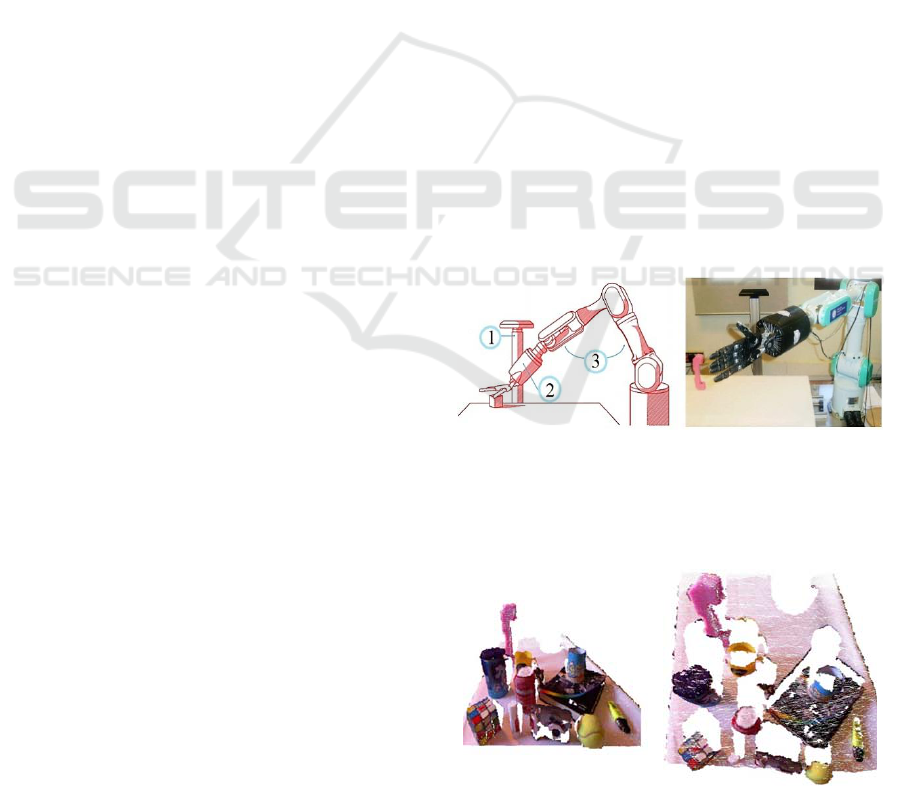
Figure 1: Robotic platform which is the scenario of this
paper: (1) The Kinect camera is located on the side,
oriented to get a top view of the objects; (2) a 20-DoF,
five-fingers anthropomorphic hand from Shadow; (3) a 7-
DoF PA-10 arm.
Figure 2: Example of a point cloud from the Kinect
camera. Left: view of the visible parts from everyday
objects lying on a table. Right: same point cloud from top
view, where empty gaps belong to occluded parts.
When an extensive database of object models is not
available or practical, more generic a priori
assumptions are required. The most common one is
to rely on the symmetries of real-life objects (Thrun
and Wegbreit, 2005). The problem then becomes to
155
Rodríguez-Jiménez S., Burrus N. and Abderrahim M..
3D Object Reconstruction with a Single RGB-Depth Image.
DOI: 10.5220/0004286401550163
In Proceedings of the International Conference on Computer Vision Theory and Applications (VISAPP-2013), pages 155-163
ISBN: 978-989-8565-48-8
Copyright
c
2013 SCITEPRESS (Science and Technology Publications, Lda.)

find the nature of the symmetries in the partial point
cloud. These are hard to estimate in practice because
of the large search space and limited data, leading
e.g. to limit the set of hypotheses to a vertical plane
axis in a restricted range (Bohg et al., 2011), or to
focus on rotational symmetries (Marton et al., 2010).
Modeling 3D objects by symmetry is a common
approach because many objects are symmetric, but
also, a large class of everyday objects, especially
when manufactured, can be generated by extruding a
2D shape through an extrusion axis. The extrusion
process is widely used by designers and engineers to
generate 3D models from 2D sketch input. This
approach is particularly adapted to the fast
reconstruction of objects lying on a flat table, which
is a common scenario in robotics, because the table
plane normal provides a natural extrusion axis. Thus,
this paper proposes to leverage this property by
reconstructing the hidden parts with an extrusion of
the top view of the objects.
The contributions of this paper are three-fold.
First, we propose a new technique to extrude an
initial sparse point cloud output by a tabletop object
detector. Second, we propose a refinement step that
takes advantage of the complementarity of the depth
and color images by carefully initializing a graph-cut
based color segmentation with the depth data.
Finally, a quantitative evaluation of the accuracy of
the reconstructed meshes is performed on a set of 12
common use objects, showing that its effectiveness
is comparable to the most recent approach using
symmetries (Bohg et al., 2011). Some preliminary
experiments for grasping applications are also
conducted using the OpenRAVE simulator
(Diankov, 2010).
2 GLOBAL OVERVIEW
For achieving our aim of the acquisition of 3D
models using a single RGB-D image, we propose an
algorithm which can be divided into two main
stages: computation of the initial volume (Section 3)
and its completion through color-based model
refinement (Section 4). These stages include several
steps which are illustrated in Figure 3.
In the first stage, a table-top object detector
identifies and extracts a cluster of 3D points
belonging to the object. Then, existing points are
extruded along the table plane normal to fill a
voxelized volume around the cluster of interest.
Object concavities may get filled during the
extrusion step, which we compensate by checking
the voxel consistency against the depth image.
Depth images output by low-cost RGB-D
cameras are usually imprecise around the object
borders, and frequently have holes due to reflections
or other optical effects. Since the color image does
not suffer from these issues, in the second stage, we
refine the object boundaries using color
segmentation. The refined set of voxels is then given
as an input to the final meshing algorithm.
3 COMPUTATION OF THE
INITIAL VOLUME
3.1 Cluster Extraction
A table top object detector similar to (Rusu et al.,
2010) is run on the depth image. The dominant 3D
plane is first fitted to the depth data using RANSAC,
then points lying outside of a prism around the table
plane are eliminated. Remaining points are then
clustered using Euclidean distances with fixed
thresholds. Clusters that are too small or do not
touch the table are eliminated. The cluster of interest
is then determined in a task-dependent way, e.g. by
choosing the most central one. To make 3D
processing faster and get a natural neighborhood
between 3D points, a voxelized volume of fixed size
is then initialized around the cluster, and the voxels
corresponding to a cluster point are labeled as
“object”. The voxel size is a user-defined parameter
depending on the desired precision/speed tradeoff.
All reconstructions shown in this paper are with
3mm voxels.
3.2 Voxel Filling by Extrusion
The objective of this step is to “fill” the occluded
parts by relying on the assumption that the object
can be approximated by an extrusion process.
Taking into account that the table plane normal
provides the natural extrusion axis for most objects,
it is not necessary to calculate the object axis to get
the extrusion direction. Instead, we consider the
table plane normal as the extrusion direction of the
top face of the object. The proposed algorithm is the
following:
1. For each voxel which is considered as “object”,
compute the line segment going from the voxel
to the plane along the plane normal.
2. Label all voxels intersecting a line segment as
“maybe object”.
VISAPP2013-InternationalConferenceonComputerVisionTheoryandApplications
156
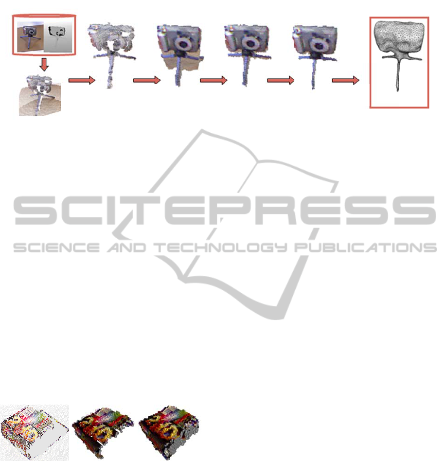
Figure 3:
to obtain
consisten
c
The res
u
object v
o
b
y runni
uncertai
n
image.
T
on the
v
data. Fo
r
empiric
a
structuri
n
in Figur
e
3.3
C
The ext
r
corresp
o
correcte
d
object”
v
b
y repro
j
compari
n
Figure 4:
of a box.
Right: v
o
p
lane. G
r
occlusio
n
If the d
i
voxel i
s
depends
sensor,
a
Kinect.
Figure 5
Color a
n
3D Sce
n
Overview of o
the initial vol
u
cy check. The
c
u
lt of this ste
p
o
lume. The
m
i
ng a morpho
l
n
ties around
T
he optimal s
t
v
oxel size a
n
r voxels of
3
a
lly found th
a
n
g element.
A
e
4.
C
onsistenc
y
r
usion step m
a
o
nd to holes
d
by checki
n
v
oxels agains
t
j
ecting each
v
n
g the projec
t
Voxel filling
b
Middle: voxeli
o
xelized mesh
r
ay voxels corr
e
n
s.
i
fference is g
r
s
labeled as
on the esti
m
a
nd is set
t
o
The output
o
.
n
d Depth Imag
e
Table
-
Obj
e
Dete
c
n
e Points
ur model acqu
i
u
me. This sta
g
c
omputed mod
e
p
is a rough
m
odel is then
s
l
ogical closin
g
object bord
e
t
ructuring ele
m
n
d the prope
r
3
mm and a
K
a
t a 3x3x3 c
u
A
n example
o
y
Check
a
y fill regions
or concavit
i
n
g the consis
t
t
the depth i
m
v
oxel onto the
t
ed depth wit
h
b
y extrusion. L
e
zed mesh of th
e
after extrusio
n
e
spond to unse
e
r
eater than a
“background
m
ated accur
a
3mm in all
o
f this proces
e
-
top
e
ct
c
to
r
V
b
y
e
i
sition process.
e includes thre
e
l is the input o
estimation o
f
s
lightly smoo
g
to cope wit
h
e
rs in the
d
m
ent size dep
e
r
ties of the
d
K
inect camera
,
u
be is a satis
fy
o
f output is g
of the object
i
es. This ca
n
t
ency of “m
a
m
age. This is
d
depth image,
h
the depth im
a
e
ft: raw point
c
e
raw object cl
u
n
towards the
t
e
n parts due to
threshold δd
,
”. The thres
h
a
cy of the
d
experiments
w
s is illustrate
V
oxel
e
xtrusion
The Kinect ca
m
e
e key points: t
a
o
f the colo
r
-
b
as
e
f
the
o
thed
h
the
d
epth
e
nds
d
epth
, we
fy
ing
g
iven
t
that
n
be
a
ybe
d
one
,
and
age.
c
loud
u
ster.
table
self-
,
the
hold
d
epth
with
e
d in
4
Af
t
ma
y
mi
s
D
f
b
el
o
tra
n
col
o
p
ro
p
ref
i
im
a
usi
n
4.
1
Th
e
seg
ge
n
av
a
Jol
l
for
e
al.,
et
a
mi
x
a u
s
to
Re
c
des
inf
o
ch
a
b
ot
h
run
de
p
ma
s
Consistency
Check
m
era provides
a
a
ble-top object
e
d refinement
m
COLO
R
REFIN
E
er the above
s
y
still have
m
s
sing or incor
r
f
rame. Incorr
e
o
ng to obje
c
n
sparent or r
e
o
r image do
p
ose to impr
o
i
ning the ob
j
a
ge and the
n
n
g image inp
a
1
Improv
Se
g
me
n
e
re are many
mentation,
bu
n
eral case. Ho
a
ilable, grap
h
l
y, 2001)
h
e
ground/back
g
2005). In pa
r
a
l., 2004) c
o
x
ture models
a
s
er provided
m
the refine
m
c
ently, Grab
C
cribed in (V
a
o
rmation
b
y
a
nnels with a
w
h
informatio
n
GrabCu
t
o
n
p
th informatio
n
s
k. This appr
o
Color-
b
a
s
Model
Refinem
e
a
depth and col
detector, voxe
m
odel stage.
-BASED
M
E
MENT
s
teps, the obt
a
issing parts a
n
r
ect depth in
f
ct pixels in t
h
c
t borders a
n
e
flective obje
c
not suffer
f
o
ve the qualit
y
j
ect segment
a
n
filling-in i
n
a
inting.
e
ment of t
h
n
tation
existing tech
n
u
t this is still
a
w
ever, when
h
-
b
ased tech
n
h
ave proven
g
round segm
e
r
ticular, the G
r
o
mbines grap
h
a
nd is design
e
m
ask. It is th
u
m
ent of an
C
ut has been
a
iapury et al
combining
w
eighting fac
t
n
in a single
e
n
ly on the c
o
n
for the initi
a
o
ach takes a g
r
ed
e
nt
Poiss
Reconst
r
l
o
r
image, whi
c
e
l filling by ext
r
M
ODEL
a
ined 3D obj
e
n
d irregularit
i
f
ormation in
t
h
e depth ima
g
n
d areas of
c
ts. Observin
g
f
rom these i
s
y
of the mod
e
a
tion using
t
n
correct dep
t
h
e Ob
j
ect
h
niques for c
o
a
n open prob
l
a good initia
l
n
iques (Bo
y
very effe
c
entation (Lo
m
G
rabCut varia
n
h cuts with
e
d to take ad
v
u
s particularl
y
initial seg
m
extended in
l
., 2010) to
u
the RGB a
n
t
or. Instead o
f
e
nergy, we p
r
o
lor image,
b
a
lization of a
n
g
reater advant
a
3D Obje
c
s
on
r
uctio
n
c
h are used
r
usion and
e
ct model
i
es due to
t
he RGB-
g
e usually
specular,
g
that the
s
sues, we
e
l by first
t
he color
t
h values
o
lo
r
-based
em in the
l
ization is
y
kov and
c
tive for
m
baert et
n
t (Rothe
r
Gaussian
v
antage of
y
adapted
m
entation.
the work
u
se depth
n
d depth
f
merging
r
opose to
b
ut using
n
accurate
a
ge of the
c
t Model
3DObjectReconstructionwithaSingleRGB-DepthImage
157
comple
m
image is
color i
n
sensitiv
e
segment
a
the initi
a
3 using
3D poi
n
Then, p
b
ackgro
u
not co
n
informa
t
p
oint, t
h
differen
t
b
elong
t
foregro
u
conside
r
b
e chan
g
robustn
e
uncertai
n
image,
o
marked
algorith
m
comput
e
Tha
n
Cut pe
r
b
ackgro
u
b
ackgro
u
4.2
H
I
n
The obt
some pi
after the
the hole
in
p
ainti
n
using n
e
depth
m
vision a
p
2011).
foregro
u
a hole-
fi
for 3D v
Foll
o
this wor
k
segment
a
surroun
d
holes ar
e
from th
e
are fille
d
"back-g
r
m
entarity of t
h
s
misleading
n
n
formation i
e
to backgr
o
a
tion. The i
n
a
l model out
p
depth inform
nt
from the
v
ixels are la
b
u
nd or unkn
o
n
sistent or
t
ion). Taking
h
e mask is c
r
t
initializatio
n
t
o foregroun
d
u
nd or backg
r
r
ed as foregr
o
g
ed by the al
g
e
ss to segme
n
n
ty associate
d
o
nly pixels w
h
using those
d
m
on the col
o
e
d mask for o
n
n
ks to the acc
u
r
forms well
u
nd have a si
m
u
nd is clutter
e
H
ole Fillin
g
n
paintin
g
ained object
xels which
h
color refine
m
filling meth
o
n
g techniques
e
ighbouring
pi
m
ap output b
y
p
proach has
b
However, i
t
u
nd/backgrou
n
fi
lling metho
d
v
ideo was pro
p
o
wing this, i
m
k
to fill miss
i
a
tion mask
d
ing values o
f
e
filled only
w
e
other "objec
t
d
only with d
r
ound" values
.
h
e technique
s
n
ear the objec
s not nece
s
o
un
d
clutter
n
itialization i
s
p
ut by the alg
o
ation only, r
e
v
olume onto
b
elled as obj
o
wn (if their
p
they do
n
this initializ
a
r
eated. Grab
C
n
values ac
c
d
, backgroun
d
r
ound. Pixels
o
und and ba
c
g
orithm and t
h
n
tation error
s
d
to edge pi
x
h
ich are not
o
d
efinitive lab
e
o
r image is t
h
n
e iteration.
u
racy of the i
n
even if the
m
ilar color di
s
e
d, as shown i
n
g
throu
g
h
D
segmentatio
n
h
ave been cl
a
m
ent do not h
a
o
ds use imag
e
to fill up th
e
i
xels. Recent
l
y
Kinect, a c
r
b
een present
e
t
does not
n
d segmentat
i
d
using depth
p
osed in (Oh
e
m
age inpainti
n
i
ng depth val
u
to fill pi
x
f
the same k
i
w
ith depth in
f
t
" pixels and
b
epth coming
.
s
, since the
d
t borders, an
d
s
sary and
m
for the i
n
thus taken
f
o
rithm of Se
c
e
-
p
rojecting e
v
the depth i
m
ect (foregro
u
p
rojected dep
t
n
ot have
d
a
tion as a sta
r
C
u
t
can take
c
ording to
pi
d
, most prob
which have
b
c
kground will
h
us ensure a
g
s
. To handle
x
els in the
d
o
n a boundar
y
e
ls. The Gra
b
h
en run usin
g
n
itial mask,
G
object and
s
tribution or i
f
n
Figure 6.
D
epth
n
is accurate
a
ssified as o
b
a
ve depth. Mo
e
interpolatio
n
e
r
emaining
h
l
y, to improv
e
r
oss-modal s
t
e
d in (Chiu e
t
benefit fro
m
i
on. Further
m
-
b
ased inpai
n
e
t al., 2009).
n
g is propos
e
u
es, but usin
g
x
els with
o
nd. Thus, o
b
f
ormation co
m
b
ackground
h
from surroun
d
d
epth
d
the
m
ore
n
itial
f
rom
c
tion
very
m
age.
u
nd),
t
h is
d
epth
r
ting
four
i
xels
b
ably
b
een
l
not
g
ood
the
d
epth
y
are
b
Cut
g
t
he
G
rab-
the
f
the
but
b
ject
st of
n or
h
oles
e
the
t
ereo
t
al.,
m
a
m
o
r
e,
n
ting
e
d in
g
the
only
b
ject
m
ing
h
oles
ding
Fig
u
con
afte
che
c
the
Fig
u
wh
e
im
a
p
os
t
un
k
Rig
h
ma
r
Th
e
20
0
ma
r
ori
g
spe
de
p
1.
2.
On
c
alg
o
im
p
u
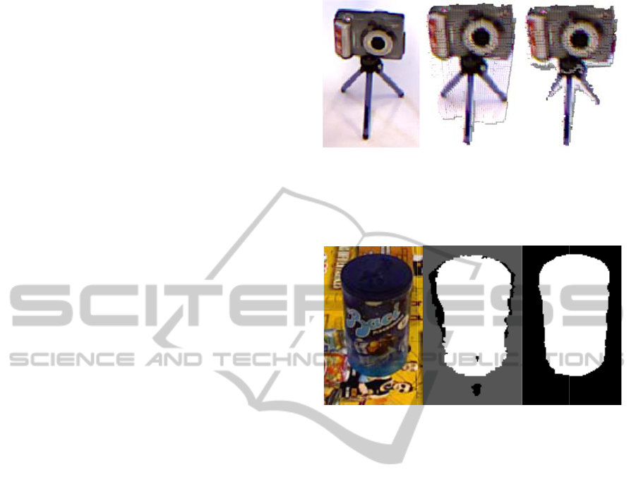
re 5: Cons
i
c
avities. Left:
r extrusion. Ri
c
k. Holes and
extrusion algo
r
u
re 6: Snapsho
e
n the foregro
u
a
ge, the object
t
er. Middle: in
i
k
nown (black),
h
t: final object
r
ked as: object
(
e
OpenCV
0
4), a fast i
n
r
ching, is
t
he
g
inal depth
cifying the pi
x
To fill the
d
p
ending on th
e
Object: the t
a
"object" pix
e
inconsistent
d
4.1. Pixels
w
marked as
t
influencing t
h
Background:
labeled as “
b
Similarly to
t
also marked
a
c
e the depth i
m
o
rithm of
S
p
rovement ob
t
i
stency check
color image.
M
g
ht: remaining
c
oncavities th
a
ithm are remo
v
t
of a refined
o
n
d is similar t
o
of interest is
t
ial segmentati
o
object (white)
segmentation,
(
white) and bac
i
mplementati
o
n
painting tec
h
used metho
d
image and
x
els to be fill
e
d
epth image,
e
pixel class:
a
rget area to
b
e
ls without
d
epth values
w
hich belong
t
t
arget area t
o
h
e inpainting.
the target are
a
b
ackground”
h
e previous c
a
a
s target area.
m
age has bee
n
S
ection 3.3
t
ained after s
e
to carve
h
M
iddle: colori
z
g
voxels after c
a
t were wrongl
y
v
ed if they are
v
o
bject segment
o
background.
L
a storage jar
o
on. Pixels are
m
)
and backgro
u
after Grabcut.
c
kground (blac
k
o
n of Tele
a
h
nique base
d
d
. It takes as
an inpainti
n
e
d.
two masks
b
e filled corre
depth value
determined i
n
t
o backgroun
d
o
prevent t
h
a correspond
s
without de
p
ase, "object"
p
n
refined and
is run ag
a
e
gmentation r
e
h
oles and
z
ed voxels
onsistency
y
filled by
v
isible.
ation even
L
eft: color
o
n a colo
r
m
arked as:
u
nd (gray).
Pixels are
k
).
a
(Telea,
d
on fast
input the
n
g mas
k
are used
sponds to
or with
n
Section
d
are also
h
em from
s
to pixels
th value.
p
ixels are
filled, the
a
in. The
e
finement
VISAPP2013-InternationalConferenceonComputerVisionTheoryandApplications
158
and dep
t
p
ixels
w
whose d
is obtai
n
(Kazhda
to creat
e
5 E
X
5.1
E
R
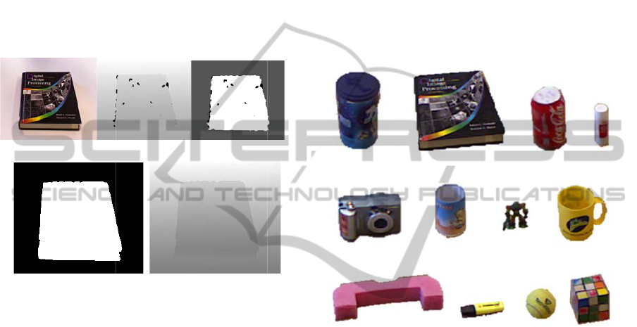
Figure 7
:
refineme
n
from the
image. (
c
p
oint fro
m
as: unk
n
(gray).
(
accordin
g
(white)
a
hole filli
n
The pro
p
12 real
o
which a
r
b
etween
our alg
o
where t
h
orientati
o
contains
calculat
e
the eva
l
referenc
e
p
ropose
d
referenc
e
commer
c
The
currentl
y
t
h in
p
ainting
w
ithout depth
epth was not
n
ed using
P
a
n et al., 200
6
e
a smooth me
X
PERIM
E
E
valuation
R
econstruc
t
(a)
(d)
:
2D images
r
n
t using a boo
k
Kinect camer
a
c
) Initial seg
m
m
the volume
n
own (black),
(
d) Final obj
e
g
to Section
4
a
nd backgroun
d
n
g through dept
h
p
osed algorit
h
o
bjects with
v
r
e shown in F
5 and 9 me
s
o
rithm in the
t
he objects l
o
ns and pl
a
72 reconstr
u
e
d from a sin
g
l
uation, the
g
e
and reco
n
d
algorithm
e
models
h
c
ial laser sca
n
processing ti
m
y
less than 2
is shown in
information
a
correct. The
fi
P
oisson surfa
c
6
) on the vox
e
sh of the obj
e
E
NTS
of the Acc
u
t
ed Mesh
(b)
r
esults of the
k
as illustrati
v
a
: (a) colo
r
i
m
m
entation re-
pr
of Section 3.3
.
object (white
e
ct segmentat
i
4
.1. Pixels are
d
(black). (e)
h
inpainting.
h
m has been
t
v
ery different
igure 8. For
e
s
hes have be
e
scenario sho
ie off the t
a
a
ces. Therefo
u
cted models
g
le view of
K
g
eometric di
f
n
structed m
e
has been
h
ave been
a
n
ner.
m
e of the w
h
seconds on
a
Figure 7, fi
l
a
nd border
pi
fi
nal objec
t
m
c
e reconstru
c
e
lized poin
t
c
l
e
ct.
u
rac
y
of th
e
(c)
(e)
colo
r
-
b
ased
m
v
e example. I
m
m
age and (b)
d
r
ojecting ever
y
.
Pixels are m
a
) and backgr
o
i
on after Gra
b
marked as: o
b
Depth image
t
ested on a s
e
sizes and sh
a
e
ach of the o
bj
e
n acquired
u
w
ed in Figu
r
a
ble in diff
e
re, the data
which have
b
K
inect camera.
f
ference bet
w
e
shes using
calculated.
a
cquired wit
h
h
ole algorith
m
a
2Ghz com
p
l
ling
i
xels
m
odel
c
tion
loud
e
m
odel
m
ages
d
epth
y
3D
a
rked
ound
a
bCut
bject
after
e
t of
a
pes,
b
ject,
u
sing
r
e 1,
e
rent
set
b
een
For
w
een
our
The
h
a
m
is
p
uter
for
sig
n
in
p
oi
n
for
co
n
(M
e
ge
o
rec
o
ali
g
(IC
dis
t
b
et
w
(
a
Fig
u
obj
e
obj
e
de
v
me
s
me
s
0.9
6
si
m
ext
r
in
c
sig
n
me
t
obj
e
al.,
20
m
me
a
sen
dif
f
tab
l
co
n
a
p
oint cl
o
n
ificantly im
p
(Bohg et al.
,
n
ts. Althou
g
the curre
n
n
sidered as fu
t
A free 3D
m
e
shLab, 201
1
o
metric dif
fe
o
nstructed 3
D
g
ned in the
s
P) is used to
t
ance to m
w
een them.
a
) Baci
(e) Camera (
f
(i) Pink Handle
u
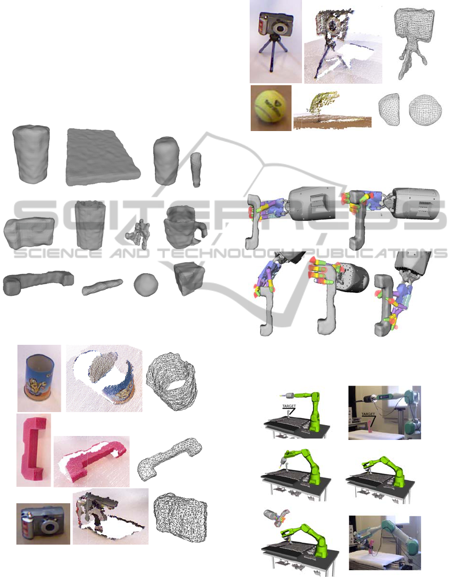
re 8: The 12
e
ct, at least 5
e
ct in different
o
Figure 9 s
h
v
iation betw
e
s
hes for all
o
s
hes is 3.87
m
6
mm. Takin
g
m
ilar to the s
e
r
usion appro
a
c
omparison
w
n
ificant impr
o
t
hod, the m
e
e
cts, indepen
d
2011) the a
v
m
m for bigge
r
It is import
a
a
surement ga
t
se that eac
h
f
erent orienta
t
l
e, as it is sho
n
sideration m
o
o
ud with les
s
p
roving com
p
,
2011) with
h this comp
u
n
t applicati
o
t
ure work.
m
esh processi
n
1
), has been
e
rence bet
w
D
models
w
s
ame space.
align the me
s
e
asure the
(b) Book
f)
Pencil Holder
(j) Pen
real objects o
f
images have
o
rientations an
d
h
ows the m
e
e
en referenc
o
bjects. The
m
m and the
g
into accou
n
e
t used in (B
a
ch provides
a
w
ith earlier sy
o
vement for l
a
an error is
l
d
ently of thei
r
v
erage error
i
r
objects.
a
nt to note
t
t
hered is stati
s
h
object im
a
t
ions and dif
f
w
n in Figure
o
st of the pos
s
s
than 3000
p
utation time
a similar n
u
u
tation time i
s
o
n, optimiz
n
g software,
used to co
m
w
een refere
n
w
hich should
Iterated Clo
s
s
hes and the
H
geometrical
(c) Can
(g) Toy (h
)
(k) Tennis
b
a
l
f the database
.
been acquire
d
d
places on the
e
an and the
c
e and rec
o
e
average err
o
standard de
v
n
t that the o
b
B
ohg et al., 2
0
a
similar eff
e
y
mmetry met
h
arge objects.
l
ess than 5
m
r
size while i
n
is less than
7
that the ex
p
s
tically very
r
a
ge was ca
p
f
erent locatio
n
10. Such set
t
sible sources
0
points,
achieved
u
mber of
s
suitable
ation is
MeshLab
m
pute the
n
ce and
be well
s
ed Point
H
ausdorff
distance
(d) Glue
)
Cup
l
l (l) Cube
.
For each
d
from the
table.
standard
o
nstructed
o
r for all
v
iation is
b
jects are
0
11), our
e
ctiveness
h
od and a
With our
m
m in all
n
(Bohg et
7
mm and
erimental
r
ich in the
p
tured in
n
s on the
t
akes into
of errors,
3DObjectReconstructionwithaSingleRGB-DepthImage
159
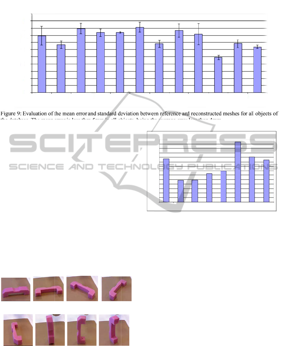
Figure 9:
the datab
a
such as
h
or other
results a
n
Figu
r
“pink h
a
visible
approxi
m
view (C
a
top-vie
w
Taki
n
this wo
r
obvious
errors le
b
e seen
differen
t
average
3mm. I
f
the sp
e
reconstr
u
p
articul
a
(a) Ca
s
(e) Ca
s
Figure 1
0
orientati
o
0
1
2
3
4
5
Average Mesh Error [mm]
Evaluation of
t
a
se. The mean
e
h
iding differe
n
optical effe
c
n
d increase t
h
r
e 11 shows
a
ndle” object
parts prov
i
m
ate the geo
m
a
se 2 and 3),
b
w
is not very i
n
n
g into accou
n
r
k is 3mm (
that we can
n
ss that the m
e
in the table
t
objects, w
h
error is 2,5
m
f
more precisi
o
e
ed and im
p
u
cted object
m
a
r task require
s
e 1 (b) Cas
e
s
e 5 (f) Cas
e
0
: The “pink
h
o
ns on the table
.
Baci
B
0
0
.5
1
1.5
2
.5
3
.5
4
.5
5
.5
2
3
4
5
t
he mean error
e
rror is less th
a
n
t geometric
d
c
ts, which a
f
h
e error.
as, due to t
h
, the error i
s
i
de enough
m
etry by an e
x
b
ut the error i
n
n
formative (
C
n
t that the vo
x
Section 3.1)
n
ot obtain re
c
e
ntioned vox
e
of the aver
a
h
ere only t
h
mm
while t
h
o
n is require
d
p
rove the
a
m
odels. This
s it.
e
2 (c) Cas
e
e
6 (g) Cas
e
h
andle” object
.
B
ook
Camer
a
and standard d
e
n 5mm in all o
b
d
etails, reflec
t
f
fect the obt
a
h
e position o
f
s
lower whe
n
information
x
trusion of its
n
creases whe
n
C
ase 6).
x
el size chos
e
then it is
fa
c
onstructions
w
e
l value. Thi
s
a
ge errors o
f
h
e Rubik’s
c
h
e rest are a
b
d
, we may sc
a
a
ccuracy of
can be done
3 (d) Cas
e
e
7 (h) Cas
e
in the 8 eval
u
a
Can Cu
p
e
viation betwe
e
b
jects, being t
h
t
ions
a
ined
f
the
n
the
to
top-
n
the
e
n in
fa
irly
with
s
can
f
the
c
ube
b
ove
a
rify
the
if a
e
4
e
8
u
ated
Fig
u
tab
l
Co
m
4.0
9
5.
2
Fig
alg
o
13
s
b
e
clo
u
ap
p
tha
n
Re
c
al
m
im
a
a g
e
an
e
obt
a
est
i
an
o
b
e
e
u
p
Glue
P
Average Mesh Error [mm]
e
n reference an
d
h
e average erro
r
u
re 11: Evalua
t
e of the “pink
m
paring to its
9
mm and the st
a
2
Model
R
u
re 12 show
s
o
rithm for th
e
s
hows object
s
obtained des
u
d. The quali
t
p
roach, but it
n
ks to the se
c
onstruction i
s
m
ost no infor
m
a
ge.
Figure 14 gi
v
e
ometry that
e
xtrusion of
t
a
ined model
i
mations for
g
o
ther camera
w
e
nough to obt
P
en Pencil
Holder
7
6.5
6
5.5
5
4.5
4
3.5
3
2.5
2
1.5
1
0.5
0
Case 1
Case 2
d
reconstructe
d
less than 4m
m
ion of the erro
r
h
andle” object
,
reference m
o
a
ndard deviati
o
R
econstru
c
s
some mesh
e
tested set of
s
for which a
v
p
ite of a ve
r
t
y of the top
v
w
as made si
g
g
mentation a
n
s
even possib
l
m
ation was
p
v
es examples
c
annot be ro
u
t
heir top-vie
w
s
are not
v
g
rasping are
w
ith a differe
n
a
in a good m
o
Pink
Handle
Rubi
k
Cub
Case 3
Case 4
C
d
meshes for al
l
m
.
r
for 8 orientat
i
,
shown in the
o
del, the mea
n
o
n is 1.49mm.
c
tion Resul
t
h
es acquired
u
12 real objec
v
ery good m
o
r
y sparse ini
t
v
iew is essent
i
g
nificantly m
o
a
nd depth fill
i
l
e in some ca
s
p
resent in th
e
of objects w
h
u
ghly approx
i
w
. Note that e
v
v
ery accurat
e
still obtaine
d
n
t point of vi
e
o
del in these
c
k
’s
b
e
Tennis
Ball
T
C
ase 5
Case 6
Ca
s
l
objects of
i
ons on the
Figure 10.
n
error is
t
s
u
sing our
t
s. Figure
o
del could
t
ial point
i
al for the
o
re robust
i
ng steps.
s
es where
e
original
h
ich have
i
mated by
v
en if the
e
, useful
d
. Adding
e
w would
c
ases.
T
oy
s
e 7
Case 8
VISAPP2013-InternationalConferenceonComputerVisionTheoryandApplications
160
5.3
A
Since g
r
p
aper, t
h
graspin
g
represen
experim
e
OpenR
A
grasps i
n
grasps f
o
(a)
B
(e) Ca
m
(i) Pin
k
Figure 1
2
objects o
f
(a)
(b)
(c)
Figure 1
3
(a), a pin
k
Middle: i
n
table). Ri
g
A
pplicatio
n
r
asping itself
h
e suitabilit
y
g
has been t
e
n
tative way.
e
nts have
A
VE simulato
r
n
many positi
o
o
r a given obj
e
B
aci
(
m
era (f) Penci
k
Handle (j
2
: Model rec
o
f
the database,
s
3
: Model recon
s
k
handle (b) a
n
nitial point clo
u
ght: final mesh
n
to Graspi
n
is not the
m
y
of the acq
u
e
sted on a s
i
Both plann
i
been pe
r
r
(Diankov, 2
0
o
ns to deter
m
e
ct, as illustr
a
(
b) Book
l Holder (g) T
o
) Pen (k) Te
n
o
nstruction res
u
s
hown in Figur
e
s
truction result
n
d a camera (c
)
u
d (white poin
t
using Poisson
r
ng
m
ain scope of
u
ired meshes
i
ngle object
a
i
ng and gras
p
r
formed w
i
0
10). It simu
l
m
ine a set of s
t
a
ted in Figure
(c) Can (d)
o
y (h) Cup
n
nis ball (l) Cu
b
u
lts of the 12
e
8.
s of a pencil h
o
. Left: color i
m
t
s correspond t
o
r
econstruction.
f
this
s
for
as a
p
ing
i
thin
l
ates
t
able
15.
Glue
b
e
real
o
lder
m
age.
o
the
(a)
(b
)
Fig
u
trip
o
init
i
rec
o
Fig
u
Op
e
gen
Fig
u
to
w
cal
c
hav
)
u
re 14: Model
o
d (a) and a te
n
i
al cluster.
o
nstruction.
u
re 15: Five
g
e
nRAVE for
a
e
rated using th
e
u
re 16: Simul
a
ard the select
e
c
ulated off-line
e
b
een perfor
m
reconstruction
n
nis ball (b). L
e
R
ight: final
g
rasps of the
g
a
pink handle
e
proposed alg
o
ted and real s
e
e
d grasping
po
previously. B
o
ed within Ope
n
results of a c
a
L
eft: color ima
g
mesh using
g
rasp table ge
n
whose mesh
o
rithm.
e
quence of the
o
sition, which
o
th planning a
n
n
RAVE.
a
mera on a
g
e. Middle:
Poisson
n
erated by
has been
trajectory
has been
d grasping
3DObjectReconstructionwithaSingleRGB-DepthImage
161

Then it can be used for online path planning in a
given scene, where the object is recognized and its
pose estimated to perform the suitable grasp, which
has been calculated off-line previously.
Figure 16 shows the sequence of the trajectory in
simulation and on the real robot of our scenario
(Figure 1), suggesting that the acquired mesh is
suitable for grasping. A more exhaustive evaluation
of grasping from a single viewpoint in simulation
and on our robotic platform is considered as future
work.
6 DISCUSSION AND FUTURE
WORK
In this paper, a method that reconstructs a model of
everyday, man-made objects from a single view has
been proposed. We have validated the precision
evaluating the difference between the reference and
the reconstructed model for 12 real objects. The
average error for all meshes is less than 4mm and
the standard deviation is less than 1mm.
Furthermore, compared to earlier methods, our
approach provides 3D models improving run-times
significantly with a similar accuracy and even, a
significant improvement both in run-time and
accuracy for bigger objects.
Experimental results with different objects
demonstrate that the obtained models are precise
enough to compute reliable grasping points. Thus,
the current system is an easy and effective approach
but it has some limitations when objects have very
thin structures, or with objects whose top-view is not
very informative. However, thanks to the generality
of the proposed algorithm, this could be
compensated by adding more cameras as needed,
applying the same technique on each view and
finally merging the resulting voxels. Furthermore,
symmetry and extrusion could complement one
another.
In the future, to handle a wider range of objects,
rotational symmetries exploitation is planned
through the combination with techniques of shape
estimation such as the work described in (Marton et
al., 2010). Moreover, for manipulation applications,
the integration of single view estimation with the
incremental model refinements techniques of e.g.
(Krainin et al., 2010) and (Krainin et al., 2011)
would be interesting. Finally, the combination of this
approach with an online grasp planner is also
planned to enable fast online grasping and
manipulation of unknown objects.
ACKNOWLEDGEMENTS
The research leading to these results has been
funded by the HANDLE European project
(FP7/2007-2013) under grant agreement ICT 231640
– http://www.handle-project.eu.
REFERENCES
Bohg, J., Johnson-Roberson, M., León, B., Felip, J.,
Gratal, X., Bergstrom, N., Kragic, D., and Morales, A.
(2011). Mind the gap-robotic grasping under
incomplete observation. In Proceedings of the IEEE
International Conference on Robotics and
Automation, pages 686–693, Shanghai, China.
Boykov, Y. and Jolly, M.-P. (2001). Interactive graph cuts
for optimal boundary amp; region segmentation of
objects in n-d images. In Proceedings of the IEEE
International Conference on Computer Vision, volume
1, pages 105–112, Vancouver, Canada.
Chiu, W., Blanke, U., and Fritz, M. (2011). Improving the
kinect by cross-modal stereo. In Proceedings of the
British Machine Vision Conference, pages 116.1–
116.10. Dundee, UK.
Diankov, R. (2010). Automated Construction of Robotic
Manipulation Programs. PhD thesis, Carnegie Mellon
University, Robotics Institute.
Kazhdan, M., Bolitho, M., and Hoppe, H. (2006). Poisson
surface reconstruction. In Symposium on Geometry
Processing, pages 61–70.
Krainin, M., Curless, B., and Fox, D. (2011). Autonomous
generation of complete 3d object models using next
best view manipulation planning. In Proceedings of
the IEEE International Conference on Robotics and
Automation, pages 5031–5037, Shanghai, China.
Krainin, M., Henry, P., Ren, X., and Fox, D. (2010).
Manipulator and object tracking for in-hand model
acquisition. In Proceedings of the Workshop on Best
Practice in 3D Perception and Modeling for Mobile
Manipulation at the IEEE International Conference on
Robotics and Automation, Anchorage, Alaska.
Kuehnle, J., Xue, Z., Stotz, M., Zoellner, J., Verl, A., and
Dillmann, R. (2008). Grasping in depth maps of time-
of-flight cameras. In International Workshop on
Robotic and Sensors Environments, pages 132–137.
Lombaert, H., Sun, Y., Grady, L., and Xu, C. (2005). A
multilevel banded graph cuts method for fast image
segmentation. In Proceedings of the IEEE
International Conference on Computer Vision, volume
1, pages 259–265, Beijing, China.
Marton, Z., Pangercic, D., Blodow, N., Kleinehellefort, J.,
and Beetz, M. (2010). General 3d modelling of novel
objects from a single view. In Proceedings of the
IEEE/RSJ International Conference on Intelligent
Robots and Systems, pages 3700–3705.
MeshLab (2011). Visual Computing Lab-ISTI-CNR,
<http://meshlab.sourceforge.net/>
VISAPP2013-InternationalConferenceonComputerVisionTheoryandApplications
162

Microsoft (2010). Kinect for Xbox 360,
<http://www.xbox.com/en-US/kinect/>
Miller, A. and Allen, P. (2004). Graspit! a versatile
simulator for robotic grasping. IEEE Robotics
Automation Magazine, 11(4):110–122.
Oh, K.-J., Yea, S., and Ho, Y.-S. (2009). Hole filling
method using depth based in-painting for view
synthesis in free viewpoint television and 3-d video. In
Proceedings of the Picture Coding Symposium, pages
1–4.
Rother, C., Kolmogorov, V., and Blake, A. (2004). "Grab-
Cut": interactive foreground extraction using iterated
graph cuts. ACM Transactions on Graphics, 23:309–
314.
Rusu, R., Bradski, G., Thibaux, R., and Hsu, J. (2010).
Fast 3d recognition and pose using the viewpoint
feature histogram. In Proceedings of the IEEE/RSJ
International Conference on Intelligent Robots and
Systems, pages 2155–2162.
Sun, M., Kumar, S. S., Bradski, G., and Savarese, S.
(2011). Toward automatic 3d generic object modeling
from one single image. In Proceedings of the
3DIMPVT, Hangzhou, China.
Telea, A. (2004). An Image Inpainting Technique Based
on the Fast Marching Method. Journal of graphics,
gpu, and game tools, 9(1):23–34.
Thomas, A., Ferrari, V., Leibe, B., Tuytelaars, T., and Van
Gool, L. (2007). Depth-from-recognition: Inferring
meta-data by cognitive feedback. In Proceedings of
the IEEE International Conference on Computer
Vision, pages 1–8.
Thrun, S. and Wegbreit, B. (2005). Shape from symmetry.
In Proceedings of the IEEE International Conference
on Computer Vision, volume 2, pages 1824–1831,
Beijing, China.
Vaiapury, K., Aksay, A., and Izquierdo, E. (2010). Grab-
cutd: improved grabcut using depth information. In
Proceedings of the ACM workshop on Surreal media
and virtual cloning, pages 57–62, New York, NY,
USA.
3DObjectReconstructionwithaSingleRGB-DepthImage
163
