
A Driving Assistance System for a Manual Wheelchair
using Servo Brakes
Daisuke Chugo
1
, Tatsuya Higuchi
1
, Yuki Sakaida
2
, Sho Yokota
3
and Hiroshi Hashimoto
4
1
School of Science and Technology, Kwansei Gakuin University, Sanda, Hyogo, Japan
2
RIKEN-TRI Collaboration Center for Human-Interactive Robot Research, Nagoya, Aichi, Japan
3
School of Science and Engineering, Setsunan University, Neyagawa, Osaka, Japan
4
Advanced Institute of Industrial Technology, Shinagawa, Tokyo, Japan
Keywords: Manual Wheelchair, Assistive Wheelchair, Servo Brakes.
Abstract: We propose a novel intelligent wheelchair based on the passive robotics. Our proposed assistive wheelchair
consists of a frame, casters, wheels and servo brakes. Our wheelchair system estimates the trajectory its user
wants using the characteristic of the row motion and realizes the estimated tracks by controlling a torque of
its servo brake. Our system requires no actuators, and its mechanism is simple and low cost. There is no risk
by malfunction of servomotors and patients can use it intuitively because they use our wheelchair passively
with their own intentional force. Our key ideas are two topics. One is the development of a passive-type
assistive wheelchair which is suitable for practical use. The other key topic is a novel driving assistance
algorithm with estimation of its user’s intention. For realizing this estimation, we use a minimum jerk
trajectory model, which expresses a typical human movement. Our proposed system compares a beginning
part of row motion by the user and this trajectory model, and estimates a whole row motion which will be
operated. Using our proposed system, the user can drive our wheelchair with a natural feeling. We test our
proposed assistance system by the experiments with our prototype and verify its effectiveness.
1 INTRODUCTION
Wheelchairs are widely used by many people who
are mobility impaired in daily activities. However,
many accidents often occur to wheelchair users and
its risk is serious. More than 80% of wheelchair
accidents are caused by environmental problems
(National Consumer Affairs Center of Japan, 2002).
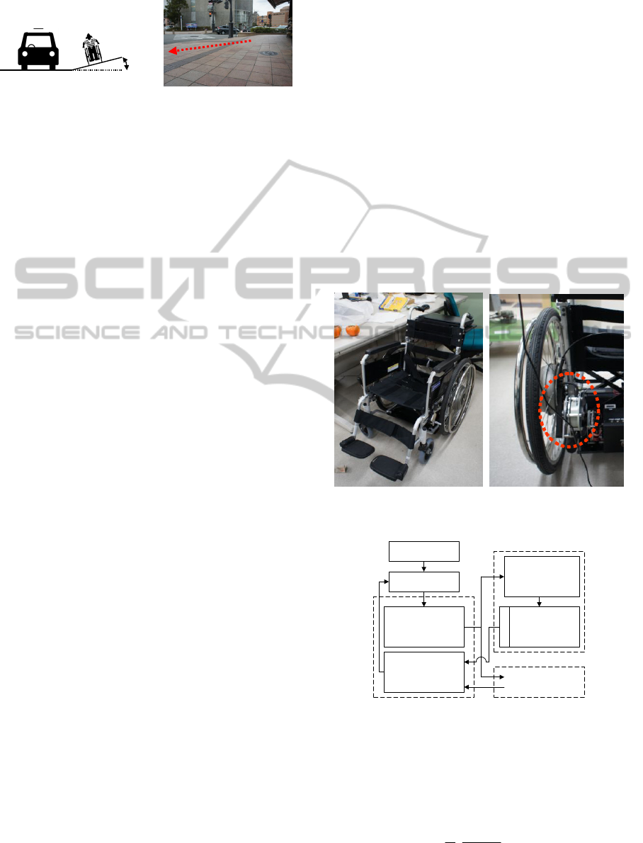
Especially, an inclination of sidewalk has high risk
for a wheelchair user. In Japan, it is permitted to
incline a sidewalk up to 5deg (Fig.1) (Japan Institute
of Construction Engineering, 2008). This inclination
leads a wheelchair user to run out from the sideway
to the roadway and it causes the accident between a
wheelchair user and a car. Therefore, a driving
assistance system for a wheelchair is important.
In previous works, a lot of assistive technologies
for wheelchairs are developed. In general, many
handicapped people traditionally use power
wheelchairs (Yamaha Motor Co., Ltd., 2012) and
previous researchers have tried to realizing
assistance functions by adding wheels with actuators
and controlling them based on the robot technology
such as motion control technology (Miller and
Slack, 1995), sensing technology and computational
intelligence (Katevas et al., 1997) (Murakami et al.,
2001). These intelligent wheelchairs provide many
functions, such as a suitable motion, an obstacle
avoidance and a navigation; thus, they provide a
maneuverable system. However, many wheelchair
users have an upper body strength and dexterity to
operate a manual wheelchair. For these wheelchair
users, its cost is too expensive and is not acceptable.
On the other hand, a manual wheelchair without
servomotors, which consists of a frame, wheels,
casters and hand brakes, is commercially available
and widely used. Its mechanism is simple and low
cost. There is no risk by malfunction of servomotors
and patients can use it intuitively because they use
these wheelchairs passively with their own
intentional force. Of course, these wheelchairs
cannot assist to drive dynamically as powered
wheelchairs and there is still a risk on a slope such
as Fig.1. Thus, there is no well-adapted wheelchair
assistance system for healthy users who have an
259
Chugo D., Higuchi T., Sakaida Y., Yokota S. and Hashimoto H..
A Driving Assistance System for a Manual Wheelchair using Servo Brakes.
DOI: 10.5220/0004477802590267
In Proceedings of the 10th International Conference on Informatics in Control, Automation and Robotics (ICINCO-2013), pages 259-267
ISBN: 978-989-8565-71-6
Copyright
c
2013 SCITEPRESS (Science and Technology Publications, Lda.)
upper body strength.
Roadway Sidewalk
5[deg]
(a) Inclination of the sidewalk (b) The typical sidewalk
Figure 1: Risks of the sidewalk.
Therefore, in this paper, we propose a passive-type
assistive wheelchair with servo brakes. We use a
concept of passive robotics. This system moves
passively based on external force without actuators.
Our system uses servo brakes, which can change
brake torque, and realizes the desired motion using
servo brakes according to the applied force and
reference tracks. For realizing a natural assistance
according to its user’s intention, we develop a novel
driving assistance scheme for a wheelchair with the
estimation of the direction which its user wants to go.
This paper is organized as follows: we introduce
a mechanical design and controller of our system in
section 2; we propose a driving assistance scheme
with the estimation of the user’s intention in section
3; we show experimental results using our prototype
in section 4; section 5 is conclusion of this paper.
2 PASSIVE-TYPE ASSISTIVE
WHEELCHAIR
2.1 Passive System
A passive system realizes a reference motion using
servo brakes with external force applied by its user.
The passive robotics system requires no actuator and
its mechanism is simple, therefore, the system will
be low cost (Goswani et al., 1990) (Rentschler et al.,
2003). In the research area of the assistive robotics,
the passive robotics concept has been used for the
walker and its performance is useful (Hirata et al.,
2007).
This characteristic is especially suitable for a
wheelchair assistance system for healthy users who
have enough upper body strength to operate a
manual wheelchair. Therefore, we adapt this concept
for our wheelchair driving assistance system.
2.2 System Configuration
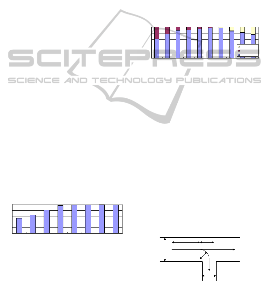
Fig. 2(a) shows our prototype. Our proposed
wheelchair utilizes a powder brake, which is one of
a servo brake. A powder brake is widely used in
industrial purposes and its cost is low comparing
with the other servo brakes. We choose the powder
brake as Fig.2(b) (ZKG-YN50, Mitsubishi Electric
Corp.), which can generate enough brake torque for
stopping 4km/h moving wheelchair with a 100kgf
user by 1sec.
Our prototype is based on a normal wheelchair
(BM22-42SB, Kawamura Cycle Co. Ltd.) and our
system has compatibility with a general wheelchair,
which fulfills these standards (ISO7193, 7176/5).
This means the user can built our system into their
wheelchair without a special construction.
Fig.3 shows its controller. Our wheelchair has
two powder brakes with the tension controller on
each wheel. Our system can measure the rotational
velocity using encoders on each wheel. All devices
including the batteries are equipped in its body and
can continue to work more than 24 hours without an
external power supply.
(a) Overview (b) Installed brake
Figure 2: Our Prototype.
Control PC
Human Interface
DA Converter
(Contec AIO-
160802AY-USB)
Tension Controller
(Mitsubishi LD-
10PAU-A)
Conuter
(Contec CNT24-
2(USB)GY)
Powder Brake
(Mitsubishi ZKG-
50YN)
Encoder
Right Wheel
Left Wheel
Same
System
Figure 3: Our Control System.
2.3 Kinematics
Fig.4 shows a kinematic relationship of our
wheelchair. The rotational radius of its trajectory R
is derived as (1).
LR
LR
vv
vvT
R
2
(1)
ICINCO2013-10thInternationalConferenceonInformaticsinControl,AutomationandRobotics
260

where the velocity of a right wheel is
R
v
and one of
a left wheel is
L
v
. The distance between the wheels
is T. If R is negative, the wheelchair turns to right
direction and if R is positive, it turns to left direction.
From (1), the ratio between
R
v
and
L
v
sets its
turning radius and in next section, we will discuss
this ratio for derivation the trajectory path.
T
Wheelchair
x
y
R
Human
v
L
v
R
v
Figure 4: Kinematic model of the wheelchair.
3 DRIVING ASSISTANCE
CONTROLLER
3.1 Concept of Our proposed
Controller
Many previous researches on the wheelchair driving
assistance control are designed for powered
wheelchairs (Katsura and Ohnishi, 2004); (Sakai et
al., 2010); (Takahashi et al., 2000) and they are
based on traction control. However, a passive system
does not generate a traction force and cannot use
these methods. Thus, we develop a driving
assistance control scheme which is based on a
velocity control.
Usually, a movement of a wheelchair consists of
two phases. In first phase, its user rows a wheelchair
and accelerates it. In this phase, a movement of the
wheelchair is based on its user’s intention. In second
phase, the wheelchair runs with inertia. In this phase,
a shape of a ground such as slopes influences
movement of the wheelchair easily.
Using its characteristic, we propose a novel
driving assistance controller for a passive-type
assistive wheelchair. Our proposed scheme estimates
a trajectory its user wants to go at a beginning of the
first phase and controls its wheels based on the
estimated result by the end of the second phase.
When the user rows the wheel again, our system
finishes this wheel control and restarts from the
estimation process.
Our estimation scheme measures a beginning
part of a row motion by the user and compares a
measuring trajectory and a minimum jerk trajectory
model which expresses a typical human motion
(Flash and Hogan, 1985); (Seki and Tadakura,
2004). After estimation the user’s intention, our
system sets the reference trajectory based on this
result and controls the servo brake for realizing it.
Our idea does not require additional force sensors.
Thus, its implementation for a general wheelchair is
easy and its cost is low.
3.2 Minimum Jerk Trajectory Model
In the field of neurophysiology, previous researchers
have analyzed voluntary human arm movements and
demonstrated that they can be closely approximated
by a minimum jerk trajectory model with
characteristic velocity profile (Flash and Hogan,
1985). This model is useful for various fields of
human robot interaction technologies (Seki and
Tadakura, 2004) and in this study, we use this model
for the estimation of a row motion by the wheelchair
user.
In the minimum jerk trajectory model, the human
arm movements, supporting one-dimensional
movement, is expressed as the trajectories which
minimize (2).
f
t
j
dt
dt
txd
C
0
2
3
3
(2)
where
f
t
is the final time of the movement and
33
dttxd
is the differential of acceleration, called
jerk.
j
C
is an extremum when
tx
is the solution
of Euler-Poisson equation. The resulting equation is
represented by (3).
0
6
6
d
t
txd
(3)
This condition shows that
tx
is the fifth order
polynomial as (4).
01
2
2
3
3
4
4
5
5
atatatatatatx
(4)
We assume the start position is
0
x
and end position
is
f
x
. Furthermore, we assume the velocity and
acceleration are zeros at the start position and the
end position, then the boundary conditions are
derived as (5).
0,0,
00,00,0
0
ffff
txtxxtx
xxxx
(5)
Appling (5) to (4),
tx
is expressed as (6) and (7).
345
00
10156
xxxx
f
(6)
ADrivingAssistanceSystemforaManualWheelchairusingServoBrakes
261

f
t
t
(7)
Using the minimum jerk trajectory model, we define
the human arm behavior characteristic on the row
movement on the wheelchair.
3.3 Estimation of the User’s Intention
Using the minimum jerk trajectory model, we
estimate the direction its user wants to go. For
realizing the estimation, we propose a following
method as show in Fig.5.
Our system measures a rotation velocity of each
wheel. If the rotation velocity of a right or left wheel
increases
t
continuously, our system judges the
user rows the wheelchair and starts to estimate the
user’s motion using the minimum jerk trajectory
model. Our system sets
2.0t
sec experimentally
and this value is derived in section 4.1.
Furthermore, our system sets the time
0
tt
at
the moment when the rotation velocity increases. At
the same time, our system measures the position
(
0
x
), velocity (
0
x
) and acceleration (
0
x
). We
assume that the boundary condition of the minimum
jerk trajectory model is as (8) (Seki and Tadakura,
2004). The velocity and the acceleration at
0
tt
are not necessarily zeros as (5) because the user may
row the hand rim and accelerate the wheelchair
when the wheelchair moves.
0,0,
,,
000
000000
ffff
ttxttxxttx
xtxxtxxtx
(8)
Using this assumption, the minimum jerk trajectory
model is derived as (9) and (10).
133
2
1683
10156
23
2
0
0
234
00
345
00
tt
x
ttx
xxxtx
f
(9)
f
t
tt
0
(10)
In (9) and (10), unknown values are end position
f
x
and the final time
f
t
. Therefore, our system uses a
pattern matching method as (11) and derives
f
x
and
f
t
which minimize
ff
txc ,
. We define the
f
x
and
f
t
which leads the minimum value of
ff
txc ,
as
0f
x
and
0f
t
.
tt
t
realffff
dttxttxxtxc
0
0
,,
(11)
where
ff
txx ,
is the trajectory model with the end
position
f
x
and the final time
f
t
.
tx
real
is
measurable value. Thus,
00
,
ff
txx
approximates
the user’s motion with the sufficient accuracy for
estimating its trajectory. In this study, we set the
candidate of these values (
f
x
and
f
t
) as (12) based
on our preliminary experiment results for reducing a
calculation load of our controller.
0.5,,2.1,1.1,0.1
50.1,,15.0,10.0,05.0
f
f
t
x
(12)
Our system excuses this matching process on each
wheel. Therefore, our system estimates
0f
x
in right
wheel (
R
f
x
0
) and in left wheel (
L
f
x
0
), and estimates
0f
t
in right wheel (
R
f
t
0
) and in left wheel (
L
f
t
0
). Our
system uses these values for the direction estimation
its user wants to go.
In (13), we estimate the average velocity in the
first phase of the wheelchair movement and we
assume this velocity shows the user’s intention.
L
f
L
f
est
L
R
f
R
f
est
R
t
x
v
t
x
v
0
0
0
0
,
(13)
where
est
R
v
is estimated velocity of right wheel and
est
L
v
is one of left wheel.
From (13), the rotational radius
est
R
of the
estimated trajectory is derived as (14). If
est
R
is
negative, the wheelchair turns to right direction and
if
est
R
is positive, the wheelchair turns to left
direction. Furthermore, when (15) is fulfilled, our
system judges that its user wants to go at straight
and sets
est
L
est
R
vv
.
straight
threshold
v
is the threshold which
is derived experimentally.
er
hand, when (22)
i
s
??f(14)
(14)
straight
threshold
est
L
est
R
vvv
(15)
If the
000
, ctxc
ff
, our system judges the user
does not row the wheelchair. In this study, we set
this threshold (
0.3
0
c
) experimentally. This value
is derived in section 4.1.
When both wheels have fulfilled this condition,
our system judges the wheelchair accelerates
ICINCO2013-10thInternationalConferenceonInformaticsinControl,AutomationandRobotics
262

without the user’s will and stops the wheelchair with
maximum brake traction for safety reason. When
only one of the wheels has fulfilled this condition,
our system judges the user turns with small radius.
In this case, our system sets the estimated value as
(16) in case of the right wheel or (17) in case of the
left wheel.
L
f
L
f
est
LR
est
R
t
x
vtvv
0
0
0
,
(16)
0
0
0
, tvv
t
x
v
L
est
L
R
f
R
f
est
R
(17)
3.4 Wheel Control Algorithm
Based on the estimated result, our system controls its
wheels with a PID controller. The control algorithm
is as follows.
For fitting the wheelchair to the estimated
trajectory, the ratio between the velocity of the right
wheel and the left wheel is same to the estimated
results. Therefore, our system defines the control
reference of both wheels (
ref
R
v
and
ref
L
v
) as (18).
ref
L
ref
R
est
L
est
R
vvvv ::
(18)
Our system uses only servo brakes for controlling
the wheelchair. Thus, when (19) is fulfilled, our
system sets the control reference as (20) and (21).
L
R
est
L
est
R
v
v
v
v
(19)
maxmax
max
vvifvv
vvifvv
R
ref
R
RR
ref
R
(20)
ref
R
est
R
est
L
ref
L
v
v
v
v
(21)
In this case, our proposed system sets
R
ref
R
vv
and
controls the left wheel. At the left wheel,
ref
LL
vv
and our system can control the velocity with its
servo brake. For safety reason, if the velocity
exceeds the limitation value
max
v
, our system
reduces its moving speed to this limitation.
On the other hand, when (22) is fulfilled, our
system sets the control reference as (23) and (24),
and controls right wheel with its servo brake.
L
R
est
L
est
R
v
v
v
v
(22)
maxmax
max
vvifvv
vvifvv
L
ref
L
LL
ref
L
(23)
ref
L
est
L
est
R
ref
R
v
v
v
v
(24)
After setting the control references, our system uses
PID controller as (25) in the left wheel or (26) in the
right wheel when its velocity does not exceed the
limitation. The control error integrates from
0
t
and
our assistance system tries to maintain the direction
at the beginning of the row motion.
dt
de
kdtekek
L
d
t
LiLpLR
0
,0
(25)
L
ref
LL
vve
(if (19) is fulfilled.)
0,
0
L
R
d
t
RiRpR
d
t
de
kdtekek
(26)
R
ref
RR
vve
(if (22) is fulfilled.)
According to (25) and (26), our system maintains the
ratio between the velocity of the right wheel and the
left wheel as (18). Therefore, our system with the
proposed algorithm, controls the wheels only for
fitting the trajectory its user wants and its velocity
depends on the user’s motion. Our system reduces
the moving speed of the wheelchair only in case of
Start
Is acceleration more than a
threshold value for
Δ
t?
System calucurates on
the both wheels.
00
,
ff
txc
Is more than
in both wheels?
00
,
ff
txc
0
c
System detects motion model and sets
the control reference.
Is acceleration more than a
threshold value for
Δ
t?
Which of the wheels rotates
the faster comparing with their
reference values?
System sets and human motion
estimation process starts.
0
tt
Emergency stop
System uses PID control for the right
wheel for realizing the estimated path
at .
0
tt
System uses PID control for the left
wheel for realizing the estimated path
at .
0
tt
All wheels
No wheel
Only left wheel
System detects motion model at right
wheel and sets the reference.
System detects motion model at left
wheel and sets the reference.
Only right wheel
Right wheel Left wheel
Yes
No
Yes
No
System ends the wheel control process
based on estimated trajectory at .
0
tt
Figure 5: Estimation and control flow of our system.
ADrivingAssistanceSystemforaManualWheelchairusingServoBrakes
263
the exceeding the limitation value
max
v
for safety
reason.
Our system applies this control algorithm during
one row motion based on its estimated trajectory,
and in next row motion, our system re-estimates the
user’s trajectory and applies this algorithm again as
Fig.5.
4 EXPERIMENTS
4.1 Parameter Derivation
Our assistance system uses two parameters,
t
is
the estimation time parameter and
0
c
is the pattern
matching parameter which judges the row motion is
done by the user or not. In this experiment, we
derive the suitable values for two parameters.
4.1.1 Estimation Time Parameter
Our system estimates the row motion of the user by
the measured wheel rotation velocity data during
t
seconds. Therefore, if our system sets
t
is large
value, our system can use the large measuring data
for estimation and the estimation accuracy will
increase. However,
t
causes the time delay and
t
should be small for increasing usability.
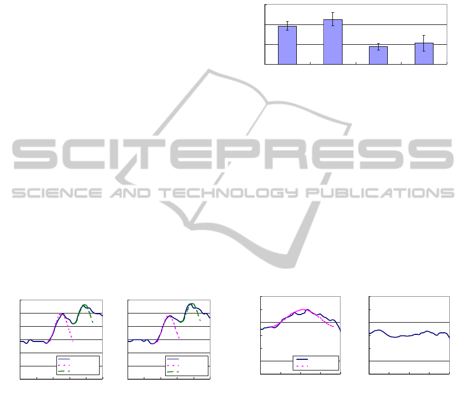
This experiment uses 810 row motions by six
subjects who use a wheelchair daily. Our proposed
system estimates the whole operation from its
t
motion at the begging. Comparing between the
estimated motion and the motion which extracted
manually, we derive the success rate as Fig.6. From
the experimental results in Fig.6, if the
t
is larger
than 0.2[sec], the estimation performance is suitable.
Therefore, we choose the smallest value from them
and set
2.0t
.
53
65
82
97 98 99 100 99
0
20
40
60
80
100
0.05 0.1 0.15 0.2 0.25 0.3 0.35 0.4
Estimation time [sec]
Success rate [%]
Figure 6: Success rate of each estimation time.
4.1.2 Pattern Matching Parameter
Our system judges the user has not performed any
motion if the pattern matching error (11) exceeds the
pattern matching parameter
0
c
. Therefore, this
parameter is important for the safety of the user.
In this experiment, we adapt this evaluation
method to the measuring data of our previous
preliminary experiment in section 4.1.1. In these
measuring data, the wheelchair accelerates 1100
times and 810 times are performed by the user’s row
motion. The experimental results are shown in Fig.7.
The positive failure is the misjudgment the human
motion as the acceleration by other reason and the
negative error is the misjudgment the acceleration by
other reason as the human motion. The negative
error is more serious problem for safety reason and
we choose
0.3
0
c
.
0%
20%
40%
60%
80%
100%
0.5 1 1.5 2 2.5 3 3.5 4 4.5 5
Threshold (C
0
)
Rate [%]
N ega tive F ailure
Positive Failure
Success
Figure 7: Success rate of each pattern matching parameter.
4.2 Field Test using our Prototype
For verifying the effectiveness of our system, we
make two experiments using our prototype. In first
experiment, we test the trajectory estimation
performance. The other experiment, we test the
performance of our wheelchair assistive system on
the slope environment.
4.2.1 Estimation of the User’s Trajectory
In this experiment, we test the proposed trajectory
estimation scheme. The subject moves on the
trajectory as Fig.8 and our system estimates it. We
test 6 cases. In each case, six subjects who are
healthy young people test our prototype ten times.
Two subjects are left-handed and four subjects are
right-handed. Fig.8 shows the experimental
environment. We show the trajectory by drawing on
the linoleum flat floor as Fig.8 and the subject
moves on it using the wheelchair according to this
trajectory.
(B) (C)(A)
3m
1.5m
1.5m
R
2.5
m
(D)
R=0.5m or 1m
(E)
Figure 8: Experimental trajectory.
ICINCO2013-10thInternationalConferenceonInformaticsinControl,AutomationandRobotics
264
The condition of each case is as follows.
Case1: The subject starts at (B) and goes straight.
Around (C), the subject accelerates the wheelchair
to (E) again. Our system estimates the trajectory at
(B) and (C).
Case2: The subject starts at (A) and goes straight
at 0.6m/s. Around (B), the subject accelerates the
wheelchair to the straight direction. Furthermore,
around (C), the subject accelerates the wheelchair
to the straight direction again. Our system
estimates the trajectory at (B) and (C).
Case3: The subject starts at (B) and turns to (E). A
turning radius is 1m. Our system estimates the
trajectory at (B).
Case4: The subject starts at (A) and goes straight
at 0.6m/s. Around (B), the subject turns to (E). A
turning radius is 1m. Our system estimates the
trajectory at (B).
Case5: The subject starts at (B) and turns to (E). A
turning radius is 0.5m. Our system estimates the
trajectory at (B).
Case6: The subject starts at (A) and goes straight
at 0.6m/s. Around (B), the subject turns to (E). A
turning radius is 0.5m. Our system estimates the
trajectory at (B).
As the results, our system judges the straight
direction in all trials in case (1) and (2). Fig.9 shows
the estimated row motion in case (2). We can verify
that our system succeeds to estimate the user’s row
motion twice in each wheel.
0
0.2
0.4
0.6
0.8
1
1.2
012345
Time [sec]
Velocity [m/sec]
Wheel Velocity
Estimation1
Estimation2
0
0.2
0.4
0.6
0.8
1
1.2
012345
Time [sec]
Velocity [m/sec]
Wheel Velocity
Estimation1
Estimation2
(a) Left wheel (b) Right wheel
Figure 9: Estimated row motion in case (2).
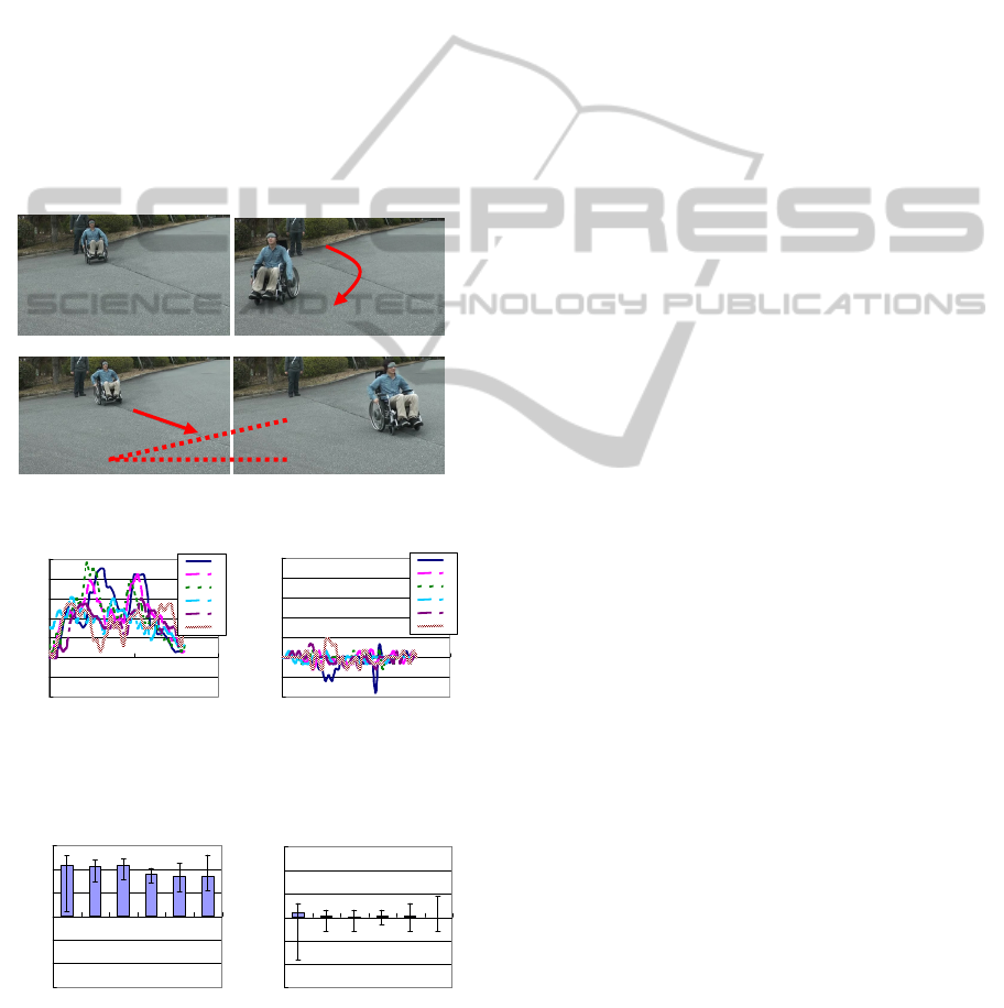
Fig. 10 shows estimated results by our proposed
system in case (3) to (6) and Fig.11 shows the
estimated row motion in case (4). In all cases, our
system can estimates the turning radius with 12%
error maximum and its accuracy is enough for
practical use. The estimated results in case (3) are
more accurate than the result in case (4). Because in
case (4), the subjects turn at (B) with 0.6m/s and it is
difficult for them to trace the trajectory accurately.
Furthermore, the subjects operate the right wheel
with the complex motion. From Fig.11(b), the
subject does not row the right wheel, however, he
coordinates the wheel velocity. Therefore, our
system misjudges the velocity of the right wheel and
in this case, estimated velocity is larger than its
actual velocity.
0
0.5
1
1.5
Case3 (R=1m) Case4 (R=1m) Case5 (R=0.5m) Case6 (R=0.5m)
Estimated Radius [m]
Figure 10: Estimated results in case (3) to (6).
The estimated results in case (5) and (6), there is
same tendency in case (3) and (4). In both cases, the
radius is 0.5m and the estimated results in case (5)
are more accurate than the result in case (6). The
disturbance of the estimated results in case (6) is
large because for realizing the reference radius
(0.5m), the subject should fix the right wheel and it
causes the complex motion at (B) point.
The estimated error by left-handed subjects and
right-handed subjects are almost same. However,
left-handed subjects turn at about 0.57m/s and right-
handed subjects turn about 0.52m/s in case (4). This
may mean right turn motion is easy for left-handed
person and in our future work, we should discuss a
dominant hand of the wheelchair user.
0
0.2
0.4
0.6
0.8
1
1.2
01234
Time [sec]
Velocity [m/sec]
Wheel Velocity
Estimation
0
0.2
0.4
0.6
0.8
1
1.2
01234
Time [sec]
Velocity [m/sec]
(a) Left wheel (b) Right wheel
Figure 11: Estimated row motion at right direction in case
(4). In the right wheel, our system detects there is no row
motion by the subject.
4.2.2 Running Test on the Slope
In this experiment, we test the performance of our
system in a typical high-risk situation to a
wheelchair user. The subject goes straight using a
wheelchair on a test load, which has 8deg inclination,
with our assistance scheme. Furthermore, for
verifying its effectiveness, the subjects do this
experiment without our system. In each case, six
subjects who are healthy young people test our
ADrivingAssistanceSystemforaManualWheelchairusingServoBrakes
265
prototype with an eye mask for removing the
influences by visual information.
As the result, the user can go straight with our
system as Fig.12(b). On the other hand, without our
assistance system, it is difficult to go straight by the
inclination as Fig.12(a). Fig.13 shows the difference
between the velocities of right and left wheel during
the experiment. When the difference is zero, the
wheelchair goes straight and when the difference is
the positive value, the wheelchair turns to the right
direction (the gravity direction) as Fig.12(a). From
Fig.13, the wheelchair goes straight with our
assistance. Fig.14 shows the average value of Fig.13.
In Fig.14(b), the maximum velocity difference is
almost same and we can verify that our controller
controls the wheels to realize the straight direction.
From these results, we can verify our system can
assist to fit the trajectory which its user wants.
(a) Without assistance
(b) With assistance
Figure 12: Test run on the slope (Subject A).
-0.2
-0.1
0
0.1
0.2
0.3
0.4
0.5
0510
Time [sec]
Velocity [m/sec]
A
B
C
D
E
F
-0.2
-0.1
0
0.1
0.2
0.3
0.4
0.5
0510
Time [sec]
Velocity [m/sec]
A
B
C
D
E
F
(a) Without assistance (b) With assistance
Figure 13: The velocity difference between a right and a
left wheel. Positive value means the wheelchair turns to
the right direction (The gravity direction).
-0.3
-0.2
-0.1
0
0.1
0.2
0.3
ABCDE F
Subject
Velocivt [m/sec]
-0.3
-0.2
-0.1
0
0.1
0.2
0.3
ABCDE F
Subject
Velocivt [m/sec]
(a) Without assistance (b) With assistance
Figure 14: The average value of the difference between
the velocities of a right and a left wheel. Positive value
means the wheelchair turns to the right direction (The
gravity direction).
5 CONCLUSIONS
In this paper, we develop a novel assistance control
for a passive-type wheelchair for healthy users who
have enough upper body strength. For realizing the
assistive wheel control, we develop the estimation
scheme for the user’s intention and our system
controls its wheels based on the estimated results.
Using our system, the user can move with the
wheelchair easily to the direction he wants.
In our future work, we will improve the user’s
motion estimation scheme. In the experiments in
section 4.2.1, the errors of the estimated trajectory
tend to be large when the subject changes the motion
rapidly. From our experiments, these motions are
characteristic and we will classify them considering
with the character of the wheelchair movement
during these motions.
ACKNOWLEDGEMENTS
This work is supported in part by Kawanishi
Memorial ShinMaywa Education Foundation.
REFERENCES
National Consumer Affairs Center of Japan, 2002.
Considering the safety of self-propelled manual
wheelchairs, In NCAC News, Vol.14, No.3, pp.4.
Japan Institute of Construction Engineering, 2008. A
Sidewalk guideline for smooth mobility, 2nd edition,
ISBN: 4802893922. (in Japanese)
Yamaha Motor Co., Ltd., 2012. JW
II, http://www.yamaha-motor.jp/wheelchair/unit/jw2/
(Available at Feb., 2013)
D. P. Miller and M. G. Slack, 1995. Design and Testing of
a Low-Cost Robotic Wheelchair Prototype, In
Autonomous Robots, Vol.2, pp.77-88.
N. I. Katevas, N. M. Sgouros, S. G. Tzafestas, G.
Papakonstantinou, P. Beattie, J. M. Bishop, P.
Tsanakas and D. Koutsouris, 1997. The Autonomous
Mobile Robot SENARIO: A Sensor-Aided Intelligent
Navigation System for Powered Wheelchairs, In IEEE
Robotics and Automation Magazine, Vol.4, No.4,
pp.60-70.
Y. Murakami, Y. Kuno, N. Shimada and Y. Shirai, 2001.
Collision avoidance by observing pedestrian’s faces
for intelligent wheelchairs, In Proc. of IEEE/RSJ Int.
Conf. on Intelligent Robots and Systems, pp.2018-
2023.
A. Goswani, M. A. Peshkin and J. Colgate, 1990. Passive
robotics: An exploration of mechanical computation,
In Proc. of IEEE Int. Conf. on Robotics and
Automation, pp.279-284.
8[de
g
]
ICINCO2013-10thInternationalConferenceonInformaticsinControl,AutomationandRobotics
266

A. J. Rentschler, R. A. Cooper, B. Blaschm and M. L.
Boninger, 2003. Intelligent walkers for the elderly:
Performance and safety testing of VA-PAMAID
robotic walker, In J. of Rehabilitation Research and
Development, Vol.40, No.3, pp.423-432.
Y. Hirata, A. Hara and K. Kosuge, 2007. Motion Control
of Passive Intelligent Walker Using Servo Brakes, In
IEEE Trans. on Robotics, Vol.23, No.5, pp.981-990.
S. Katsura and K. Ohnishi, 2004. Human Cooperative
Wheelchair for Haptic Interaction Based on Dual
Compliance Control, In IEEE Trans. on Industrial
Electronics, Vol.51, No.1, pp.221-228.
K. Sakai, T. Yasuda and K. Tanaka, 2010. Power assist
effects of a new type assist unit in a one hand drive
wheelchair with a triple ring, In Proc. of the IEEE/RSJ
Int. Conf. on Intelligent Robots and Systems, pp.6040-
6045.
Y. Takahashi, S. Ogawai and S. Machida, 2000. Step
climbing using power assist wheel chair robot with
inverse pendulum control, In Proc. IEEE Int. Conf. on
Robotics and Automation, pp.1360-1365.
T. Flash and N. Hogan, 1985. The coordination of arm
movements: an experimentally confirmed
mathematical model, In J. of Neurosicence, Vol.5,
No.7, pp.1688-1703.
H. Seki and S. Tadakura, 2004. Minimum Jerk Control of
Power Assisting Robot based on Human Arm
Behavior Characteristics, In Proc. of IEEE Int. Conf.
on Systems, Man and Cybernetics, pp.722-727.
ADrivingAssistanceSystemforaManualWheelchairusingServoBrakes
267
