
Robust Pictorial Structures for X-ray Animal Skeleton Tracking
Manuel Amthor, Daniel Haase and Joachim Denzler
Computer Vision Group, Friedrich Schiller University of Jena, Jena, Germany
Keywords:
Landmark Tracking, Pictorial Structures, X-ray Videography, Animal Locomotion Analysis.
Abstract:
The detailed understanding of animals in locomotion is a relevant field of research in biology, biomechanics
and robotics. To examine the locomotor system of birds in vivo and in a surgically non-invasive manner,
high-speed X-ray acquisition is the state of the art. For a biological evaluation, it is crucial to locate rele-
vant anatomical structures of the locomotor system. There is an urgent need for automating this task, as vast
amounts of data exist and a manual annotation is extremely time-consuming. We present a biologically moti-
vated skeleton model tracking framework based on a pictorial structure approach which is extended by robust
sub-template matching. This combination makes it possible to deal with severe self-occlusions and challeng-
ing ambiguities. As opposed to model-driven methods which require a substantial amount of labeled training
samples, our approach is entirely data-driven and can easily handle unseen cases. Thus, it is well suited for
large scale biological applications at a minimum of manual interaction. We validate the performance of our
approach based on 24 real-world X-ray locomotion datasets, and achieve results which are comparable to
established methods while clearly outperforming more general approaches.
1 INTRODUCTION
The in-depth understanding of animal locomotion is
an ongoing field of research with relevant applica-
tions in biology (Fischer and Lilje, 2011; Stoessel and
Fischer, 2012), biomechanics (Brainerd et al., 2010;
Nyakatura et al., 2012), and robotics, and includes the
development of mathematical models for locomotion,
obtaining a detailed understanding of evolution or de-
veloping walking robots. Especially avian bipedal
locomotion represents a suitable testbed for detailed
studies due to the large variety of existing species with
different properties such as body size, mass, limb pro-
portions, as well as walking speed and behavior. To
examine the locomotor system of birds in vivo and in
a surgically non-invasive manner, high-speed X-ray
acquisition is the state of the art. As the animal to
be analyzed is usually placed on a treadmill, X-ray
videography provides an unbiased and highly detailed
insight into locomotion characteristics. A typical X-
ray recording setup and the resulting data is exemplar-
ily shown in Fig. 1 and described in detail in (Stoessel
and Fischer, 2012). To allow for highly accurate stud-
ies and analyses, recordings are generally performed
at a high spatial and temporal resolution—in our case
1536 × 1024 pixels at a frame rate of 1 kHz.
This huge amount of data, on the other hand, has a
big drawback at the same time, as the biological eval-
(a) (b)
Figure 1: (a) X-ray recording procedure during locomotion
showing a quail (A) on a treadmill (C) within the X-ray
acquisition system (B). The corresponding acquired data
frame is shown in (b).
uation heavily relies on finding anatomical landmarks
such as hip joints, knee joints, or the feet in each
frame of a recorded sequence. Until today, the au-
tomated localization of those landmarks is still in its
infancy and often has to be performed by human ex-
perts, as self-occlusions of the locomotor system dras-
tically complicate this task. In (Gatesy et al., 2010),
for instance, a 3D skeleton model is fitted manually to
X-ray scans of animals. However, for biological and
biomechanical purposes, large-scale studies including
thousands of sequences are highly desirable but are
only feasible if a time-consuming manual interaction
is avoided.
In this paper, our goal is to overcome limitations
of recent approaches for X-ray tracking in animal lo-
comotion scenarios. In particular, our focus is to pro-
351
Amthor M., Haase D. and Denzler J..
Robust Pictorial Structures for X-ray Animal Skeleton Tracking.
DOI: 10.5220/0004693403510359
In Proceedings of the 9th International Conference on Computer Vision Theory and Applications (VISAPP-2014), pages 351-359
ISBN: 978-989-758-009-3
Copyright
c
2014 SCITEPRESS (Science and Technology Publications, Lda.)

vide a novel data-driven tracking approach which uses
global information while being robust to local occlu-
sions and does not rely on any training data. Thus, a
fully automated application to large amounts of data
is possible at a minimum of user interaction.
In Sect. 2, we give an overview of related work
and motivate our approach. Sect. 3 briefly presents
the methods which form the basis for our extended
tracking method, while our proposed robust tracking
approach is discussed in Sect. 4. The evaluation of
our approach on real-world datasets is given Sect. 5.
2 RELATED WORK AND
MOTIVATION
For the challenging problem of landmark tracking
in X-ray locomotion scenarios, Active Appearance
Model (AAM) (Cootes et al., 1998; Edwards et al.,
1998; Cootes et al., 2001; Matthews and Baker, 2004)
based approaches have successfully been applied in
several variations in recent years (Haase et al., 2011;
Haase and Denzler, 2013). One substantial practi-
cal drawback for the application to large amounts
of recorded data, however, is that AAMs need to be
trained on labeled example data (Haase and Denzler,
2011a). Furthermore, as for instance described in
(Gross et al., 2005), trained AAMs do not general-
ize well to unseen cases. In our scenario, this in-
cludes changes in locomotion behavior or birds of
different morphology. Therefore, AAMs are in gen-
eral only applicable for the particular locomotion se-
quence they were trained on. Our goal in this paper is
to overcome these practically relevant shortcomings
for X-ray locomotor tracking by using a solely data-
driven approach without any need of training data.
One possibility for entirely data-driven tracking
are standard local approaches such as optical flow or
template matching. In (Amthor et al., 2012), how-
ever, it is shown that not only these standard meth-
ods, but also an occlusion-robust extension of tem-
plate matching fails to track all landmarks due to local
ambiguities and disturbances. Based on these find-
ings, the data-driven method to be employed must be
global, i.e. the locomotor system must be modeled as
a whole.
A prominent method which allows data-driven
modeling of articulated objects is the concept of
pictorial structures (Felzenszwalb and Huttenlocher,
2005; Felzenszwalb and Huttenlocher, 2000; Fischler
and Elschlager, 1973), a form of deformable part-
based models (Felzenszwalb et al., 2010). Depend-
ing on the type of appearance model, no training is
necessary (Felzenszwalb and Huttenlocher, 2000), al-
though more complex variations exist which rely on
training data (Andriluka et al., 2009; Zuffi et al.,
2012; Pishchulin et al., 2013). Due to frequent self-
occlusions of relevant anatomical parts during loco-
motion, however, standard pictorial structures without
any form of occlusion handling are likely to fail in our
X-ray scenario. Therefore, in this work we aim to ex-
tend global pictorial structure models (Felzenszwalb
and Huttenlocher, 2000) with robust local matching
approaches (Amthor et al., 2012) to combine the ad-
vantages of global modeling and local occlusion ro-
bustness while still avoiding the need of training data.
3 BACKGROUND
In the following, a brief overview of the two main
approaches which form the base of our robust part-
based skeleton tracking method are presented, namely
sub-template matching and pictorial structures.
3.1 Sub-template Matching
The basic idea of standard template tracking is to ex-
tract a template T
T
T in the first image of a sequence
I
I
I
1
, . . . , I
I
I
L
and to recover the best matching template
configuration such as position (x, y), orientation θ, or
scale s in subsequent frames. This procedure is based
on a particular matching function f
T
T
T
I
I
I
,
(x, y, θ, s)
which determines how well template T
T
T matches im-
age I
I
I given the template configuration (x, y, θ, s). A
typical choice for f is based on the cross correlation
coefficient, which can efficiently be computed using
the frequency domain. The optimal transformation
( ˆx, ˆy,
ˆ
θ, ˆs) of a template T
T
T with respect to an image
I
I
I is given by
( ˆx, ˆy,
ˆ
θ, ˆs) = argmax
x,y,θ,s
f
T
T
T
I
I
I, (x, y, θ, s)
. (1)
One major disadvantage of standard template
matching is its failure in the case of occlusions
(Amthor et al., 2012), as even partial disturbances
in the search image I
I
I can drastically bias the tem-
plate matching results. The main idea of sub-template
matching (Jurie and Dhome, 2002; Ishikawa et al.,
2002) is to overcome this problem by exploiting the
fact that non-occluded parts of an image can still be
used to estimate the correct template transformation
when considering them individually. As suggested
in (Jurie and Dhome, 2002; Ishikawa et al., 2002)
this approach can be implemented by dividing the en-
tire template T
T
T into K sub-templates S
S
S
1
, . . . , S
S
S
K
and
determining the score function for each of them in-
dependently. The main challenge then is to merge
VISAPP2014-InternationalConferenceonComputerVisionTheoryandApplications
352

T
S
1
S
2
S
3
S
4
I
f
S
1
I, (x, y)
f
S
2
I, (x, y)
f
S
3
I, (x, y)
f
S
4
I, (x, y)
f
T
I, (x, y)
(a)
(b)
(c)
Figure 2: Sub-template matching example: (a) Original
template T
T
T showing an X-ray recording of a bird’s leg.
The template is split into four sub-templates S
S
S
1
, . . . , S
S
S
4
.
(b) Search image I
I
I with partial occlusion. (c) Individual
sub-template scores f
S
S
S
1
(I
I
I, (x, y)), . . . , f
S
S
S
4
(I
I
I, (x, y)) and av-
eraged score f
T
T
T
(I
I
I, (x, y)). Rotation and scale were omitted
in this example for the sake of clarity. The matching re-
sults for the non-occluded sub-templates S
S
S
1
, S
S
S
2
, S
S
S
4
are con-
sistent, while S
S
S
3
provides erroneous estimates caused by oc-
clusions. The final template score f
T
T
T
(I
I
I, (x, y)) in the right-
most column, however, shows that the biased matching of
S
S
S
3
is averaged out and a correct estimation for the entire
template is obtained.
the matching results of all sub-templates into one fi-
nal estimation for the entire template. In both (Ju-
rie and Dhome, 2002) and (Ishikawa et al., 2002),
this task is solved by making a hard decision for
each sub-template, i.e. each sub-template votes for
exactly one possible transformation. In contrast,
(Amthor et al., 2012) use a soft approach for sub-
template fusion which is motivated by three funda-
mental observations for occlusions in the given X-
ray scenario: (i) non-occluded sub-templates pro-
vide correct matching results, (ii) partially occluded
sub-templates might still provide a peak at the cor-
rect position in the pose space, and (iii) full oc-
clusions of sub-templates provide random matching
results. As a consequence, the fusion of all sub-
templates is performed by averaging their particular
scores f
S
S
S
1
I
I
I, (x, y, θ, s)
, . . . , f
S
S
S
K
I
I
I, (x, y, θ, s)
in the
pose space, i.e.
( ˆx, ˆy,
ˆ
θ, ˆs) = argmax
x,y,θ,s
f
T
T
T
I
I
I, (x, y, θ, s)
(2)
with
f
T
T
T
I
I
I, (x, y, θ, s)
=
1
K
K
∑
k=1
f
S
S
S
k
I
I
I, (x, y, θ, s)
. (3)
An example of this soft sub-template matching
procedure is shown in Fig. 2 for the case of the X-ray
scenario at hand. In Fig. 2(a), the original template
T
T
T including its division into sub-templates S
S
S
1
, . . . , S
S
S
4
is depicted. Fig. 2(b) shows a scenario in which
the original template is partially occluded by another
anatomical structure. The resulting matching scores
f
S
S
S
1
I
I
I, (x, y)
, . . . , f
S
S
S
4
I
I
I, (x, y)
are shown in the left
column of Fig. 2(c), but only template translation
(x, y) is considered for the sake of simplicity. It can
be seen that the non-occluded sub-templates S
S
S
1
, S
S
S
2
, S
S
S
4
have correct matching results, while S
S
S
3
is occluded
and does not match correctly. The final template score
f
T
T
T
I
I
I, (x, y)
is given in the right column of Fig. 2(c)
and shows that the erroneous result of the occluded
sub-template is averaged out.
3.2 Pictorial Structures
Pictorial Structures (PS) (Felzenszwalb and Hutten-
locher, 2000; Felzenszwalb and Huttenlocher, 2005;
Fischler and Elschlager, 1973) are an instance of de-
formable part-based models, i.e. an object is repre-
sented by connected rigid sub-components. In the
case of pictorial structures, the parts are connected
by spring-like connections, and the appearance of
each part can be modeled in a general manner, al-
lowing for intensity features as well as for more com-
plex feature representations (Felzenszwalb and Hut-
tenlocher, 2000). The connections between parts of a
pictorial structures model are represented by a graph
G = (V, E), where the vertices V = {v
1
, . . . , v
N
} cor-
respond to the N model parts and the edges E ⊆
V × V specify pairwise connections between those
parts. While in general the structure of G can be ar-
bitrary, in the following we assume a tree structure as
this allows for an efficient optimization of the model
(Felzenszwalb and Huttenlocher, 2000).
Each instance of a given pictorial structures
model is fully characterized by the configuration l
l
l =
(l
l
l
1
, . . . , l
l
l
N
), where l
l
l
n
are the positional parameters
such as position, orientation, and scale of part v
n
.
Given the part configuration l
l
l
n
, the matching qual-
ity of part v
n
with respect to an image I
I
I is denoted by
g
n
(I
I
I, l
l
l
n
). For the case of intensity features, g
n
(I
I
I, l
l
l
n
)
can easily be assessed via template matching. Ad-
ditionally, for each pair (v
n
1
, v
n
2
) of connected parts,
h
n
1
,n
2
(l
l
l
n
1
, l
l
l
n
2
) measures how likely the relative posi-
tioning of parts v
n
1
and v
n
2
is for a given model. The
optimal configuration
ˆ
l
l
l of a pictorial structures model
for a search image I
I
I is then defined by
ˆ
l
l
l = argmax
l
l
l=(l
l
l
1
,...,l
l
l
N
)
∑
v
n
∈V
g
n
(I
I
I, l
l
l
n
) + (4)
∑
(v
n
1
,v
n
2
)∈E
h
n
1
,n
2
(l
l
l
n
1
, l
l
l
n
2
)
.
As shown in (Felzenszwalb and Huttenlocher, 2000),
the solution of this equation is equivalent to the max-
imum a posteriori (MAP) estimate and can efficiently
be computed using dynamic programming.
RobustPictorialStructuresforX-rayAnimalSkeletonTracking
353

hip joint
pelvis
femur
tibiotarsus
tarsometatarsus
phalanges
(x
n
,y
n
)
Θ
n
S
n,k
knee joint
heel joint
foot joint
Figure 3: Schematic representation of the relationship be-
tween the anatomical structure of a bird (Nyakatura et al.,
2012) and our part-based model approach (example show-
ing one leg of a jackdaw). On the left hand, the division
into sub-templates S
S
S
n,k
of a single part and the correspond-
ing configuration l
l
l
n
is shown.
4 ROBUST PICTORIAL
STRUCTURES
In the following, our occlusion-robust extension of
standard pictorial structures is presented in detail.
While our approach is generic and can be applied
to any kind of data standard pictorial structures are
suited for, we focus on the X-ray animal skeleton
tracking scenario as example application. Firstly, in
Subsect. 4.1, we describe the extended pictorial struc-
ture framework. In Subsect. 4.2, optimization tech-
niques for our extended model are presented.
4.1 Model Definition
Our basic model is identical to original pictorial struc-
tures (Felzenszwalb and Huttenlocher, 2000) as de-
fined in Subsect. 3.2, i.e. the object to be tracked is di-
vided into N parts whose connections are represented
by a graph G = (V, E). For a given model config-
uration l
l
l, the matching quality of a given pictorial
structure can be assessed via Eq. 4. For our biolog-
ical skeleton tracking application, the model has a
tree structure originating at the pelvis, while the re-
maining parts cover the two legs, with a single bone
per part. In this specific application, there is no need
for spring-like connections between individual model
parts used in (Felzenszwalb and Huttenlocher, 2000).
Instead, we use revolute joints similar to anatomical
joints, which simplifies Eq. 4 to
ˆ
l
l
l = argmax
l
l
l=(l
l
l
1
,...,l
l
l
N
)
∑
v
n
∈V
g
n
(I
I
I, l
l
l
n
). (5)
Note, however, that this simplification is not essential
for the extension presented in the following.
To include robust sub-template tracking into the
pictorial structures model defined above, we choose
the matching function g
n
to be based on tem-
plate matching as in (Felzenszwalb and Huttenlocher,
2000). This step allows us to easily replace g
n
with
the robust sub-template-based version f
n
(cf. Eq. 3),
i.e. the matching quality of each part v
n
with regard to
a given image I
I
I is assessed on a sub-template basis.
As a result, we can insert the sub-template matching
formulation from Eq. 3 into Eq. 5 and obtain
ˆ
l
l
l = argmax
l
l
l=(l
l
l
1
,...,l
l
l
N
)
∑
v
n
∈V
f
n
(I
I
I, l
l
l
n
)
= argmax
l
l
l=(l
l
l
1
,...,l
l
l
N
)
∑
v
n
∈V
K
n
∑
k=1
f
S
S
S
n,k
I
I
I, l
l
l
n
, (6)
where K
n
is the number of sub-templates of part v
n
,
S
S
S
n,k
is the k
th
sub-template of v
n
, and f
S
S
S
n,k
I
I
I, l
l
l
n
determines how well this sub-template matches the
search image I
I
I for a given configuration l
l
l
n
of v
n
.
With this formulation, the optimal model parameters
ˆ
l
l
l = (
ˆ
l
l
l
1
, . . . ,
ˆ
l
l
l
N
) are specified, for which the pictorial
structure best matches the given image I
I
I while be-
ing robust to local occlusions of the individual model
parts.
4.2 Optimal Model Fitting
To fit the extended pictorial structure model to a given
image I
I
I, several methods can be applied. The na
¨
ıve
way of a direct search—i.e. testing all reasonable pa-
rameter combinations of the model—is not of practi-
cal use, as it has a complexity which is exponential in
the number of model parts N.
In (Felzenszwalb and Huttenlocher, 2000) it was
shown that the paradigm of dynamic programming
(DP) can be used to solve the original pictorial struc-
tures formulation. In the following, we show that this
property still holds for our robust extension by pre-
senting an optimal DP algorithm for Eq. 6. Following
(Cormen et al., 2001), the main steps of DP in our
scenario are (i) the recursive definition of an optimal
solution, and (ii) the construction of an optimal solu-
tion, both of which will be described below.
Recursive Definition. We assume that the part con-
nection graph G has a tree structure with root node
VISAPP2014-InternationalConferenceonComputerVisionTheoryandApplications
354

v
n
root
. To reformulate the optimal solution, we de-
fine the function F
n
I
I
I, (x, y)
which for every possi-
ble position (x, y) of part v
n
gives the best matching
quality of the entire sub-model consisting of v
n
and
all of its children. As schematically shown in Fig. 3,
each part v
n
determines the starting position (x
0
, y
0
)
for each of its child parts, and consequently the opti-
mal parameters for the sub-model containing v
n
and
all of its children depend on the matching quality of
v
n
itself and the matching quality of all child parts of
v
n
. For any leaf node v
n
leaf
, however, no child parts
are present, and the optimal parameters only depend
on the matching quality of v
n
leaf
and the starting point
(x
0
, y
0
) defined by the parent part of v
n
leaf
. Thus, the
optimal solution for the full model can be formulated
recursively in a bottom-up fashion by starting with all
leave nodes v
n
leaf
, for which we have
F
n
leaf
I
I
I, (x, y)
= max
θ,s
f
n
leaf
I
I
I, (x, y, θ, s)
. (7)
The optimal matching results of non-leaf parts can
then be defined recursively by
F
n
I
I
I, (x, y)
= max
θ,s
f
n
I
I
I, (x, y, θ, s)
+
∑
v
m
∈ch(v
n
)
F
m
I
I
I, (x
0
, y
0
)
, (8)
where ch(v
n
) denotes the set of all child nodes of v
n
and (x
0
, y
0
) is the starting position of all child nodes of
v
n
and is entirely determined by the configuration of
v
n
. To be able to recover the optimal values of θ and
s in a later step, we additionally define the function
Q
n
I
I
I, (x, y)
as the argmax equivalent of Eq. 8, i.e.
Q
n
I
I
I, (x, y)
= argmax
θ,s
f
n
I
I
I, (x, y, θ, s)
+ (9)
∑
v
m
∈ch(n)
F
m
I
I
I, (x
0
, y
0
)
.
In terms of the recursive definition given in Eq. 8, the
globally optimal matching score F
global
for the entire
model is given by
F
global
= max
x,y
F
n
root
I
I
I, (x, y)
. (10)
Note that for above scheme the memoization tech-
nique should be used to avoid redundant calculations
by re-using previously computed values.
Construction of Optimal Solution. Due to the
bottom-up recursive formulation of the optimization
problem, the solution can now be constructed in a top-
down manner starting with v
n
root
. Based on Eq. 10, the
globally optimal position ( ˆx
n
root
, ˆy
n
root
) of v
n
root
can be
found via
( ˆx
n
root
, ˆy
n
root
) = argmax
x,y
F
n
root
I
I
I, (x, y)
. (11)
The remaining configuration parameters of v
n
root
, i.e.
ˆ
θ
n
root
and ˆs
n
root
can then be obtained from Q
n
root
via
(
ˆ
θ
n
root
, ˆs
n
root
) = Q
n
root
I
I
I, ( ˆx
n
root
, ˆy
n
root
)
. (12)
On the basis of l
l
l
n
root
= ( ˆx
n
root
, ˆy
n
root
,
ˆ
θ
n
root
, ˆs
n
root
), the
position ( ˆx
n
ch
, ˆy
n
ch
) of each child node v
n
ch
∈ ch(v
n
root
)
of v
n
root
can be calculated. These values, in turn, can
then be used to look up
ˆ
θ
n
ch
and ˆs
n
ch
for each child
node using Q
n
ch
I
I
I, ( ˆx
n
ch
, ˆy
n
ch
)
. The reconstructed
optimal configuration l
l
l
n
ch
= ( ˆx
n
ch
, ˆy
n
ch
,
ˆ
θ
n
ch
, ˆs
n
ch
) can
now be used to determine the optimal starting point
for the child nodes of v
n
ch
itself—this process is re-
peated until a leaf node is reached. Once all leaf nodes
have been processed, the full globally optimal model
configuration
ˆ
l
l
l = (
ˆ
l
l
l
1
, . . . ,
ˆ
l
l
l
N
) is determined.
5 EXPERIMENTS AND RESULTS
In the following, we present evaluations of our pro-
posed method which are based on a wide variety of
real-world X-ray bird locomotion datasets. We use
a total of 24 individual locomotion sequences which
comprise quails, a bantam chicken, jackdaws, tina-
mous, and lapwings. All sequences were recorded
for zoological and biomechanical studies presented in
(Stoessel and Fischer, 2012, quails, jackdaws, tina-
mous), (Nyakatura et al., 2012, lapwing), and (Haase
and Denzler, 2011b, bantam, one quail). All datasets
were acquired at a frame rate of 1000 frames per sec-
ond and at a resolution of 1536×1024 pixels. Ground
truth landmarks were provided by biological experts
for at least every 10
th
frame of a sequence. In total
the data used for the evaluations contains more than
33,000 frames and 150,000 manual landmark annota-
tions. An overview of the examined datasets is pre-
sented in Table 1.
Because the recorded X-ray images also con-
tain non-animal objects (i.e. background) such as the
treadmill, the background information was automati-
cally removed from all images prior to the evaluation
using the method suggested in (Haase et al., 2013).
The qualitative evaluation is based on the Euclidean
distance between the tracking results and the corre-
sponding ground truth landmark positions.
We compared our method to original pictorial
structures (Felzenszwalb and Huttenlocher, 2000) and
to established methods for X-ray locomotion analysis,
namely single bone sub-template matching (Amthor
RobustPictorialStructuresforX-rayAnimalSkeletonTracking
355
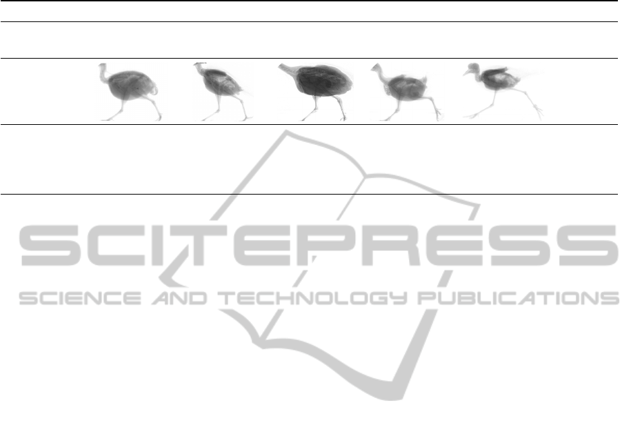
Table 1: Overview of the 24 real-world bird locomotion datasets used for experimental evaluation. The datasets were recorded
during the studies presented in (Stoessel and Fischer, 2012, quails, jackdaws, tinamous), (Nyakatura et al., 2012, lapwing),
and (Haase and Denzler, 2011b, bantam, one quail).
SPECIES
TOTAL
QUAIL
(Coturnix
coturnix)
JACKDAW
(Corvus
monedula)
TINAMOU
(Eudromia
elegans)
BANTAM
(Gallus
gallus)
LAPWING
(Vanellus
vanellus)
5
EXAMPLE
IMAGES
INDIVIDUALS/
SEQUENCES
5/9
3/6 2/6 1/1 1/2 12/24
FRAMES
13,841 9,080 6,070
796
3,528 33,315
GROUND-
TRUTH
LANDMARKS
49,652 20,761 70,002 2,160 7,500 150,075
et al., 2012), standard AAMs (Haase and Denzler,
2011a), and augmented AAMs (Haase and Denzler,
2013). The underlying part model—used for stan-
dard pictorial structures as well as for our method—
comprises 8 parts as shown in Fig. 5 and was con-
structed based on the anatomical structures pelvis, fe-
mur, tibiotarsus, and tarsometatarsus. The root is
located at the pelvis and contains both legs as child
parts. For each sequence, we initialize the part-model
by using one manually annotated frame. Note that for
the application at hand, this initial frame is chosen to
feature as few occlusions as possible, but occlusions
can not be avoided entirely. However, we apply no
special treatment for the initialization process and let
our algorithm handle the occlusions. In subsequent
frames, the initial model configuration is predicted by
a Kalman filter framework. The search space between
two frames was set to 35 × 35 pixels for translation,
±5
◦
for rotation and 2% for scale. For the other meth-
ods, the same parameter settings as suggested in the
original papers were used. In addition to quantitative
results (cf. Fig. 4), qualitative results are provided in
Fig. 5.
5.1 Comparison to Standard Pictorial
Structures
As mentioned in the previous sections, general tem-
plate matching used for pictorial structures can not
deal with severe occlusions occurring in the X-ray
datasets. To verify this assertion, we tested standard
pictorial structures (Felzenszwalb and Huttenlocher,
2000) and compared the results to our final approach.
To ensure a fair comparison, both our method and pic-
torial structures use the identical framework and only
differ in the template matching method.
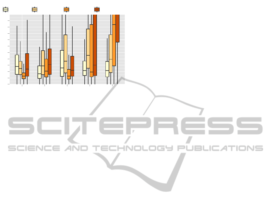
Fig. 4 shows the quantitative tracking results for
all 24 datasets by landmark groups. As can be seen,
tracking median errors can be reduced substantially
by our approach for almost all landmark groups, espe-
cially for the knee landmarks. Here, the error of 20–
25 pixels is decreased to 10–15 pixels. The improve-
ment of tracking performance becomes even more
distinct when considering the upper quartile errors.
For standard pictorial structures, these errors range
between 45 and 80 pixels for knee, heel, and foot
joints. In contrast, our approach does not exceed the
limit of 25 pixels for all landmarks. Hip landmarks,
however, show slightly larger errors compared to the
standard pictorial structures. Summing up, however,
we can state that our presented approach is clearly
more robust and achieves a higher accuracy than stan-
dard pictorial structures.
5.2 Comparison to Single Bone
Tracking
The tracking framework presented in (Amthor et al.,
2012) was designed to reliably determine the motion
of outer torso landmarks via the tracking of single
bones.
Again, the results for all available datasets are pre-
sented in Fig. 4. As can be seen, the performance of
the single bone method in the case of the foot land-
marks is slightly better than the performance of our
approach. This can be explained by the fact that the
single bone method was especially designed for track-
ing the tarsometatarsi and the heel and foot land-
marks. Thus, it is to be expected that for these land-
mark groups the single bone technique is superior to
the combined skeleton model tracker, as no further
context has to be considered. In the case of the hip
landmarks, the single bone approach provides better
results on average. This behavior is a bit surpris-
ing at first, since severe ambiguities should disturb
the tracking results without global knowledge about
VISAPP2014-InternationalConferenceonComputerVisionTheoryandApplications
356
Approach
Euclidean Error [px]
0
5
10
15
20
25
30
35
40
45
50
Ours AAAM STM PS AAM
Landmark Category
Hip Joints Knee Joints Heel Joints Foot Joints
Figure 4: Quantitative evaluation of our approach compared
to pictorial structures (PS) (Felzenszwalb and Huttenlocher,
2000), single bone sub-template matching (STM) (Amthor
et al., 2012), standard active appearance models (AAM)
(Haase and Denzler, 2011a), and augmented Active Ap-
pearance Models (AAAM) (Haase and Denzler, 2013). Our
presented approach clearly outperforms PS and AAM and
slightly improves established methods for X-ray locomo-
tion while avoiding the need of training data.
the remaining anatomical structures. However, land-
marks of both hips are very close to each other and
confusions about the actual leg are unlikely to cause
large tracking errors. Thus, substantial errors should
occur for the single bone tracker at the knee land-
marks if ambiguities are resolved incorrectly consid-
ering the femur or the tibiotarsus which can be con-
firmed considering Fig. 4. Here the median error is
improved by 5 pixels while the upper quartile error is
improved by even 20 pixels. This advantage of our
approach is an important improvement of the single
bone tracker, as an exact distinction of the knee land-
marks is crucial for biological applications.
5.3 Comparison to AAMs
As discussed in Sect. 2, AAMs are well-studied for
the given X-ray locomotion domain. To evaluate our
approach, a comparison to standard AAMs (Haase
and Denzler, 2011a; Haase et al., 2011) as well as a
comparison to augmented AAMs (Haase and Denzler,
2013) is conducted on all 24 available datasets.
The tracking results for all 24 datasets are shown
in Fig. 4. The worst results for outer-torso landmarks
are obtained by standard AAMs, which is caused
by non-linear shape activities and non-discriminative
texture information of the lower leg landmarks. As
augmented AAMs were designed to overcome these
drawbacks of standard AAMs, results of the former
are more consistent and have a median error of merely
10–15 pixels for all landmarks.
Our approach, however, provides worse results
for the hip landmarks for reasons discussed in Sub-
sect. 5.1. Errors for the lower leg landmarks, on
the other hand, are slightly smaller. Considering the
third quartile, our approach shows an improvement
of 10 pixels for the knee and heel joints compared
to augmented AAMs. Based on the fact that our
method only has to be initialized for the first frame
while AAMs require a substantial amount of anno-
tated training images, we can state that our approach
is more suited for the application to large amounts of
data.
5.4 Runtimes
The presented combined skeleton model tracking
framework was solely implemented in C/C++ using
the OpenCV library v2.4. The experiments were
performed on an Intel
R
Core
TM
2 Duo CPU E8400
standard desktop computer @3.00 GHz. The track-
ing speed obtained in our experiments was about 0.5
frames per second on average. For one frame, the
computation is performed for all landmarks of the en-
tire locomotor system, i.e. hip, knee, heel, and foot
landmarks of both legs. Similar to (Amthor et al.,
2012), the computation times heavily depend on the
number of used sub-patches. Hence, it is possible
to decrease computational effort by reducing tracking
reliability. In our scenario, accuracy is much more im-
portant than real time tracking—thus, the parameters
were selected accordingly.
6 CONCLUSIONS AND FURTHER
WORK
We have presented a robust, fully data-driven ap-
proach for the combined locomotor system tracking
in X-ray videography of bird locomotion. By the fu-
sion of robust single bone tracking and pictorial struc-
ture models, we are able to reliably track most of the
landmarks even in cases of severe occlusions and con-
sequential occurring ambiguities. The main benefit of
our approach is the capability to only need one labeled
frame to train the model, whereas model-driven ap-
proaches such as AAMs, deformable part models and
sample based methods require a substantial amount
of training samples. Furthermore, even unseen cases
can be handled reliably, in contrast to existing model-
driven methods. Based on exhaustive experiments we
showed that our combined approach is comparable to
established methods of the X-ray locomotion analysis
scenario, while non-specialized methods were clearly
outperformed.
RobustPictorialStructuresforX-rayAnimalSkeletonTracking
357
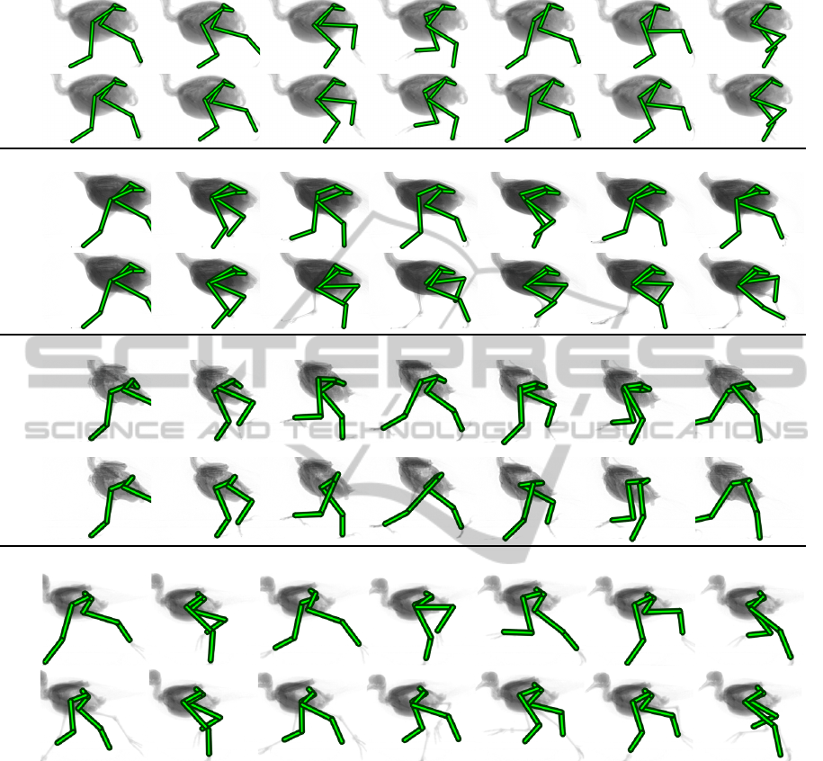
Quail
OursAAAM
Tinamou
OursPS
Jackdaw
OursSTM
Lapwing
Ours
AAM
Figure 5: Qualitative evaluation of our approach compared to results obtained by pictorial structures (PS) (Felzenszwalb and
Huttenlocher, 2000), single bone sub-template matching (STM) (Amthor et al., 2012), standard Active Appearance Models
(AAM) (Haase and Denzler, 2011a), and augmented Active Appearance Models (AAAM) (Haase and Denzler, 2013).
An interesting point for future work would is the
extension to a 3D model using further camera views,
both X-ray as well as visible light cameras.
ACKNOWLEDGEMENTS
The authors would like to thank Alexander St
¨
oßel
from the Department of Human Evolution at the
Max-Planck-Institute for Evolutionary Anthropology
in Leipzig, Germany for providing the quail, jackdaw,
and tinamou datasets. Furthermore we would like to
thank John Nyakatura from the Institute of Systematic
Zoology and Evolutionary Biology with Phyletic Mu-
seum at the Friedrich Schiller University of Jena, Ger-
many for providing the bantam and lapwing datasets,
as well as one additional quail dataset.
This research was supported by grant DE 735/8-1
of the German Research Foundation (DFG).
REFERENCES
Amthor, M., Haase, D., and Denzler, J. (2012). Fast and ro-
VISAPP2014-InternationalConferenceonComputerVisionTheoryandApplications
358

bust landmark tracking in x-ray locomotion sequences
containing severe occlusions. In VMV, pages 15–22.
Andriluka, M., Roth, S., and Schiele, B. (2009). Pictorial
structures revisited: People detection and articulated
pose estimation. In CVPR, pages 1014–1021.
Brainerd, E. L., Baier, D. B., Gatesy, S. M., Hedrick,
T. L., Metzger, K. A., Gilbert, S. L., and Crisco, J. J.
(2010). X-ray reconstruction of moving morphology
(XROMM): Precision, accuracy and applications in
comparative biomechanics research. J. Exp. Zool. A,
313A(5):262–279.
Cootes, T. F., Edwards, G. J., and Taylor, C. J. (1998).
Active appearance models. In Burkhardt, H. and
Neumann, B., editors, Proceedings of the 5th Euro-
pean Conference on Computer Vision, volume 1407
of LNCS, pages 484–498. Springer.
Cootes, T. F., Edwards, G. J., and Taylor, C. J. (2001). Ac-
tive appearance models. PAMI, 23(6):681–685.
Cormen, T. H., Leiserson, C. E., Rivest, R. L., and Stein, C.
(2001). Introduction to Algorithms. The MIT Press
and McGraw-Hill Book Company, 2 edition.
Edwards, G. J., Cootes, T. F., and Taylor, C. J. (1998).
Face recognition using active appearance models. In
ECCV, volume 1407, pages 581–595.
Felzenszwalb, P. F., Girshick, R. B., McAllester, D. A.,
and Ramanan, D. (2010). Object detection with
discriminatively trained part-based models. TPAMI,
32(9):1627–1645.
Felzenszwalb, P. F. and Huttenlocher, D. P. (2000). Effi-
cient matching of pictorial structures. In CVPR, pages
2066–2075.
Felzenszwalb, P. F. and Huttenlocher, D. P. (2005). Pictorial
structures for object recognition. IJCV, 61(1):55–79.
Fischer, M. and Lilje, K. (2011). Dogs in Motion. VDH.
Fischler, M. A. and Elschlager, R. A. (1973). The repre-
sentation and matching of pictorial structures. IEEE
Transactions on Computers, 100(1):67–92.
Gatesy, S., Baier, D., Jenkins, F., and Dial, K. (2010). Sci-
entific rotoscoping: a morphology-based method of
3-d motion analysis and visualization. Journal of Ex-
perimental Zoology Part A: Ecological Genetics and
Physiology, 313(5):244–261.
Gross, R., Matthews, I., and Baker, S. (2005). Generic vs.
person specific active appearance models. Image and
Vision Computing, 23(12):1080–1093.
Haase, D., Andrada, E., Nyakatura, J. A., Kilbourne, B. M.,
and Denzler, J. (2013). Automated approximation of
center of mass position in x-ray sequences of animal
locomotion. J. Biomech., 46(12):2082–2086.
Haase, D. and Denzler, J. (2011a). Anatomical landmark
tracking for the analysis of animal locomotion in x-
ray videos using active appearance models. In SCIA,
pages 604–615.
Haase, D. and Denzler, J. (2011b). Comparative evalu-
ation of human and active appearance model based
tracking performance of anatomical landmarks in lo-
comotion analysis. In Proceedings of the 8th Open
German-Russian Workshop Pattern Recognition and
Image Understanding (OGRW-8-2011), pages 96–99.
Haase, D. and Denzler, J. (2013). 2d and 3d analysis of ani-
mal locomotion from biplanar x-ray videos using aug-
mented active appearance models. EURASIP Journal
on Image and Video Processing, 45:1–13.
Haase, D., Nyakatura, J. A., and Denzler, J. (2011). Multi-
view active appearance models for the x-ray based
analysis of avian bipedal locomotion. In DAGM,
pages 11–20.
Ishikawa, T., Matthews, I., and Baker, S. (2002). Efficient
image alignment with outlier rejection. Technical Re-
port CMU-RI-TR-02-27, Carnegie Mellon University
Robotics Institute.
Jurie, F. and Dhome, M. (2002). Real time robust template
matching. In BMVC.
Matthews, I. and Baker, S. (2004). Active appearance mod-
els revisited. IJCV, 60(2):135–164.
Nyakatura, J., Andrada, E., Grimm, N., Weise, H., and Fis-
cher, M. (2012). Kinematics and center of mass me-
chanics during terrestrial locomotion in northern lap-
wings (Vanellus vanellus, charadriformes). J. Exp.
Zool. A, 317:580–594.
Pishchulin, L., Andriluka, M., Gehler, P., and Schiele, B.
(2013). Poselet conditioned pictorial structures. In
CVPR, pages 588–595.
Stoessel, A. and Fischer, M. S. (2012). Comparative intral-
imb coordination in avian bipedal locomotion. The
Journal of Experimental Biology, 215:4055–4069.
Zuffi, S., Freifeld, O., and Black, M. J. (2012). From pic-
torial structures to deformable structures. In CVPR,
pages 3546–3553.
RobustPictorialStructuresforX-rayAnimalSkeletonTracking
359
