
Electromagnetic Emission of an Optical-to-BroadR-Reach Converter
Dennis Degueldre, Thomas Waas and Markus Kucera
Computer Science and Mathematics, OTH-Regensburg, Prfeninger Strasse, Regensburg, Germany
Keywords:
BroadR-Reach, EMC, Media Converter.
Abstract:
The automotive solution for Ethernet is BroadR-Reach, which cannot be found as a common Ethernet-interface
in the consumer industry. Hence a media converter from IEEE 802.3 Ethernet to BroadR-Reach is needed to
debug and test the communication of automotive devices under test (DUT). If the functionality of a BroadR-
Reach connection has to be tested for electromagnetic compatibility (EMC), a BroadR-Reach to optical media
converter is needed, which has to comply to the same EMC test specifications as the DUT. This research
explains the internal structure of a media converter and defines a test setup for copper bound emission test of
BroadR-Reach. By using a standardized stripline measurement like it is common for electromagnetic emission
test, it could be shown, that the tested Technica/Tinytron media converter can safely be used inside an EMC
chamber.
1 INTRODUCTION
Current automotive bus systems are not able to ful-
fil bandwidth demands of future automotive applica-
tions. A promising alternative solution is the use of
switched Ethernet in a vehicle. Ethernet provides high
data rates and it is possible to create different topolo-
gies within a switched Ethernet network. One solu-
tion is the BroadR-Reach technology which enables
a data rate of 100 Mbit/s over unshielded twisted pair
cables. This adapted physical layer for automotive
use makes Ethernet more cost-effective to reduced
wiring effort, reduced shielding effort, and reduced
connector cost (Bruckmeier, 2010).
The OPEN (One Pair Ethernet Network) Alliance
(OPEN Alliance, 3 05) is enabling a wide scale adop-
tion of Ethernet-based automotive connectivity. The
main goal is to establish industry standards for Eth-
ernet connectivity over an unshielded single twisted
pair cable. This alliance was founded in November
2011 and is supported by the vehicle industry, suppli-
ers and chip manufacturers. The OPEN Alliance is a
central point where open questions with Ethernet for
in-vehicle use are discussed and solutions are devel-
oped.
One of the open questions is how to qualify the DUTs
inside of an electromagnetic test chamber. This is an
electromagnetic shielded chamber where the emission
and the immunity of Electronic Control Units (ECU)
can be tested under realistic conditions. Therefore all
the network and control lines are connected to a coun-
terpart inside or outside of the chamber to communi-
cate with an residual bus simulation or control real
actors. Since an copper based connection in or out
of the chamber would influence the EMC measure-
ments, all connections to the outside of the chamber
have to be optical. This avoids distortion of the mea-
sured data while having an eye on electromagnetic
emission. This is the field of application for optical
Ethernet-to-BroadR-Reach media converters.
2 GOAL OF THIS PAPER
This paper gives a look in the inside of an BroadR-
Reach media converter and explains how a conversion
between optical Ethernet and BroadR-Reach is done
to understand which stages in the conversion can in-
fluence the quality of the signal. To guarantee that the
media converter itself does not add any distortions to
the whole system under test, it is measured separately
under the same conditions and requirements to qual-
ify its electromagnetic compatibility. The goal is to
verify, that the EMC limits - in this paper the limits
from BMW Group Standard 95002(BMW Group, 4
10) - are not exceeded.
131
Degueldre D., Waas T. and Kucera M..
Electromagnetic Emission of an Optical-to-BroadR-Reach Converter.
DOI: 10.5220/0004711401310135
In Proceedings of the 4th International Conference on Pervasive and Embedded Computing and Communication Systems (PECCS-2014), pages
131-135
ISBN: 978-989-758-000-0
Copyright
c
2014 SCITEPRESS (Science and Technology Publications, Lda.)

3 RELATED WORK
Broadcom is the inventor and the first chip manu-
facturer of BroadR-Reach with unshielded 2-wire ca-
bling technology (Broadcom, 3 05). There are no
public investigations available about the electromag-
netic compatibility of their technology. Several EMI
(Electromagnetic Interference) and EMC (Electro-
magnetic Compatibility) measurements were done by
the automotive OEMs and first tier suppliers with the
two wire Ethernet approach under automotive condi-
tions (Verdon and Tazebay, 3 09) (Strobl, 0 25). The
results have shown that the technology has proven its
capabilities for data communication in vehicles. The
BroadR-Reach standard is completed by the OPEN
Alliance, where several compliance and test specifi-
cations are defined. The goal of those tests is the rat-
ification of the standard but not of the built up prod-
ucts. The signal quality of the products is influenced
by the layout, the used filter topologies, shielding and
the connectors used. Therefore tests have to be made
for each new product. Especially in case of a media
converter for in EMC test chamber use the neutrality
has to be ensured to avoid distortion while measuring.
With focus on the two port converters there are
three commercial media converters on the market.
One is an 100BASE-TX to BroadR-Reach ”Back-
to-Back” media converter from Continental Automo-
tive GmbH. This converter was the first on the mar-
ket and was developed for internal laboratory- and
demonstrator use. It is available at Continental Engi-
neering Services (Continental Engineering Services,
3 07). An enhanced, electromagnetic compatible ver-
sion is currently in development. The second and
the third are media converters from Technica Engi-
neering/tinytron. A 100BASE-TX and one optical
Ethernet-to-BroadR-Reach converter (Technica Engi-
neering, 3 07). Especially the optical version was
designed to be used in an EMC test chamber and is
evaluated within this research. This makes this de-
vice the only commercial media converter which was
designed for in EMC chamber use.
4 FUNDAMENTALS
4.1 BroadR-Reach
BroadR-Reach is an IEEE 802.3 Ethernet based tech-
nology which allows to send data with a data rate
of 100 Mbit/s over an unshielded twisted pair of ca-
bles. It was invented to provide a high data rate con-
nection for existing old office buildings which are
not equipped with Cat.5e cables, but rather two wire
phone cables.
BroadR-Reach defines a physical layer which uses a
different coding scheme than IEEE 802.3. So in dif-
ference to 100BASE-TX which uses two pairs of ca-
bles, BroadR-Reach uses only one. On top of that it
was optimized to fulfil automotive EMC and EMI re-
quirements. Therefore, it uses a three stage pulse am-
plitude modulation (PAM-3) with a fundamental fre-
quency of 33.3 MHz. This technology is available as
a single physical layer transceiver (PHY) or as bridg-
ing IC with several integrated standard and BroadR-
Reach interfaces. As typical for an Ethernet PHY it
supports the standard interfaces to the MAC (Media
Access Control) Layer via Media Independent Inter-
face (MII), Gigabit MII (GMII) or Serial GMII (SG-
MII) which can be directly connected to a small form-
factor pluggable (SFP) interface.
4.2 Small Form-factor Pluggable
Interface
The description SFP is used for a hot-pluggable and
swappable device that contains a transceiver as well
as the interface connector. A SFP module consists of
a PHY with SGMII interface and the necessary sup-
ply voltage regulators for the PHYs sub-voltages. The
SFP port was intended to be a modular transceiver
for optical interfaces with different wavelength like
1000BASE-SX, 1000BASE-LX or for 1000BASE-T.
But today there are also implementations with a re-
verse compatibility to 10/100BASE-TX.
4.3 Generalized Structure of a Media
Converter
Simple media converters consist of two PHYs which
are connected with each other over MII. So data can
be converted from one PHY over MII to another PHY.
This hardware configuration is called Back-to-Back-
converter and can be used for every Ethernet-based
communication where the data rate of the first and
the second PHY is equal. Otherwise the slower PHY
would not be able to transport the higher amount of
data and discard data packets.
5 STRUCTURE OF THE
TECHNICA / TINYTRON
MEDIA CONVERTER
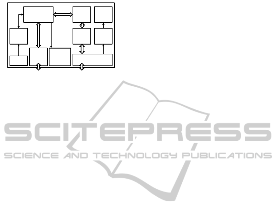
Figure 1 shows the block diagram of the Tech-
nica/tinytron BroadR-Reach-to-optical Ethernet me-
dia converter. These blocks are influencing the qual-
PECCS2014-InternationalConferenceonPervasiveandEmbeddedComputingandCommunicationSystems
132
PHY
(BCM54810S)
SFP
Con.
Power
CMC
Linear
power
supply
Signal
filter
Signal
CMC
Switch
MDC
MDIO
BR/PWR Con.
SGMII
BR
Signal
Indicators
µC
BroadR-
Reach
Figure 1: Block diagram of a Technica/tinytron optical
Ethernet-to-BroadR-Reach media converter.
ity of the BroadR-Reach signal and are explained in
the following. Arrows which are double headed show
a bidirectional information flow. The thick arrows
represent the flow of the information which is con-
verted from one medium to another. The location of
the blocks resembles to the layout of the circuit board.
The converter has two main connectors. One for the
digital SGMII connection to the SFP module and the
other as a lockable Tyco connector for the analog
BroadR-Reach and the power supply. To avoid dis-
tortion the power line is filtered with a common mode
choke (CMC) and the supply voltage is divided to the
necessary sub voltages 3.3 and 1.2 V by linear regula-
tors. This spares filtering of switched power supplies.
The analog and the digital parts are well separated
from each other. Like the power line the BroadR-
Reach signal is lead through a CMC and then filtered
with a multi-stage LC-filter. Although the dimension-
ing of the filter components and the selection of the
CMC is significant for the signal integrity, it is still
under development and requires an Non Disclosure
Agreement (NDA) from Broadcom, thus not part of
this research. After the signal is processed by the
PHY, in this case a BCM54810S with internal GMII
to SGMII converter, the SGMII is connected to the
SFP Plug to interconnect for example with the PHY
in a SFP Module with LC Connector for optical data
transmission. A simple microcontroller initializes the
BroadR-Reach PHY and reads out two dual in line
package (DIP) switches. The DIPs are used for con-
figuration of common transmission parameters since
autonegotiation is not used in the car. One is the se-
lection which side is the clock source (master) or sink
(slave). The other choses if the the output power is
in half or full out mode. More about that can be
read in the data sheet of the PHY (Broadcom, 3 05).
Two LEDs show the link state and the activity of the
BroadR-Reach connection. Link and activity of the
SFP can be seen on some versions of the transceiver.
6 MEASUREMENT SETUP
6.1 Test Environment and Preset
All measurements were made in an automotive certi-
fied EMC test chamber which is calibrated weekly.
Since the described media converter is used to test
and qualify a DUT, the converter itself has to ful-
fil the same requirements to electromagnetic copper
bound emission. Therefore, the emission has to be
qualified with the same requirements as the tested
DUT. This EMC requirements can vary between the
projects and their client. One of these specifications
is the BMW group standard for electromagnetic com-
patibility GS 95002 (BMW Group, 4 10) and was cho-
sen because of its representativity. This standard de-
scribes several measurement setups, their fields of ap-
plication, preferences and limit lines.
It was chosen to evaluate the emission with the
stripline antenna and a measurement receiver. In this
method the DUT, in this case only the data line, is
placed under a stripline antenna which is connected
to a measurement receiver. This receiver interprets
the signal. This signal is then read out by a soft-
ware which presets the receiver, triggers the mea-
surement and logs the results. Table 1 shows the
used receiver model and measurement settings de-
fined from suggestions in GS 95002. All measure-
ments were made with the Rhode & Schwarz ESC30
in Fast Fourier Transformation (FFT) mode. The de-
tectors average and peak were set which built their
result over the dwell time. The frequencies start at fs-
tart and are stepped with fstep until fstop is reached.
The IF-bandwidth of the used receiver internal input
bandpass-filter is IF-BW.
6.2 Measurement Setup
The Hardware of the test setup consists of two
BroadR-Reach nodes. A block diagram of the test
environment can be seen in figure 2. Node A (left)
and B (right) are realized with an Technica/tinytron
media converter as explained in section 5. In this
setup node A is set to master and node B to slave.
Otherwise there would be no active link between the
nodes. A and B are configured to full output power.
Both nodes were connected with a ”Dacar 609 FLR-
CUAGY 2x0.18 AX” cable from Leoni.
The nodes were supplied from outside of the chamber.
This power supply line is filtered over an EMC filter
from the outside to the inside of the chamber to avoid
distortions and connected to an artificial network in-
side of the chamber to simulate in-vehicle behavior.
Since optical communication has no electromagnetic
ElectromagneticEmissionofanOptical-to-BroadR-ReachConverter
133
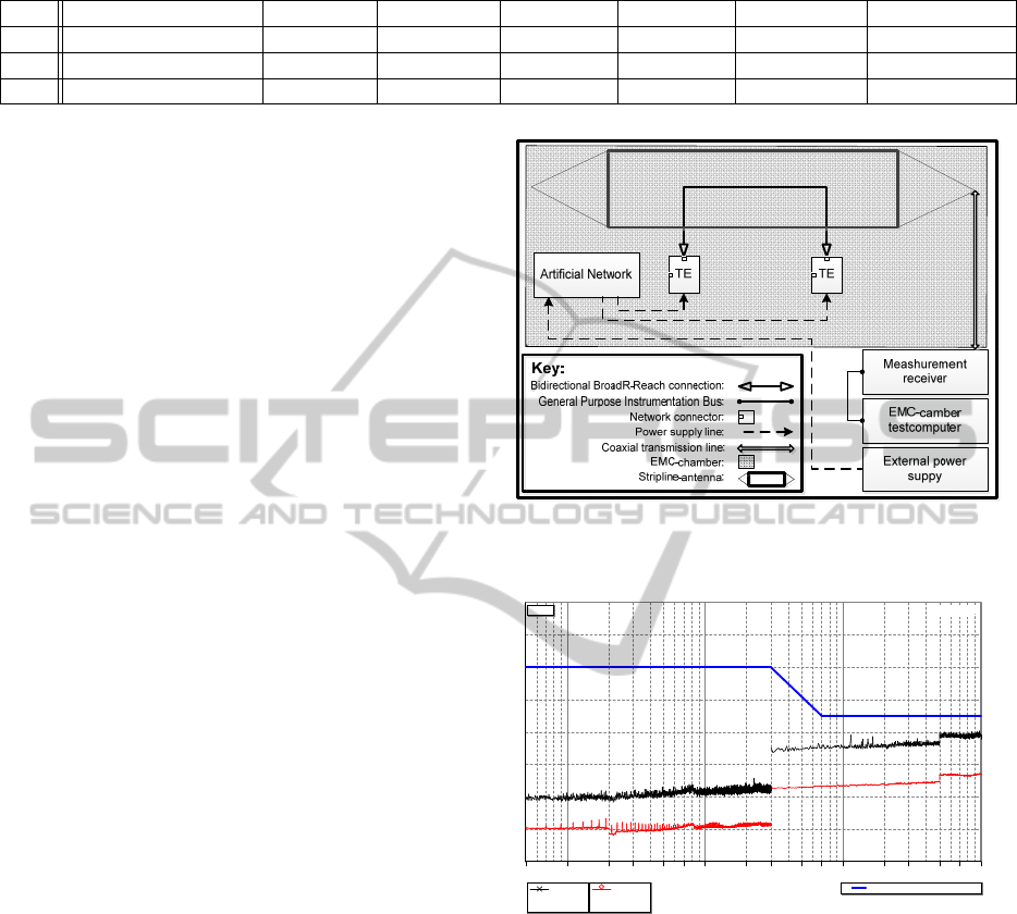
Table 1: Measurement receiver settings from table 9 in GS 95002.
No. Receiver Detectors fstart [Hz] fstop [Hz] fstep [Hz] If-BW [Hz] dwell time [s]
1 FFT ESCS30, 9kHz Pk, Av 500 k 2 M 3.1 k 9 k 200 m
2 FFT ESCS30 Pk, Av 2 M 30 M 3.1 k 9 k 200 m
3 FFT ESCS30 Pk, Av 30 M 1 G 49 k 12 k 100 m
emission, the SFP module is plugged in but not con-
nected with optical fibers.
After the measurement setup was completely built up
and wired inside of the chamber, the media convert-
ers were plugged out from power while the external
power supply was still on and a baseline measurement
was made. This ensures correct working of the power
input filters and gives a feedback if the receivers are
working correctly. Additionally it gives a statement
about the noise floor which helps to interpret the fol-
lowing measurement. This baseline of the media con-
verter noise floor was measured with the settings from
table 1 and can be seen in figure 3. The blue line
(starts at at 30 dbu V) is the limit line suggested by
GS 95002. The black (starts at -10 dbu V) and the
red line (Start at -19 dbu V) are the detector results
for peak and average. It can be seen, that the graph
is running parallel without any high spikes. The dis-
continuity can be explained with the different receiver
settings and the resulting measurement range of the
receiver.
After the noise floor measurement showed no exter-
nal influence of the environment, the converters were
supplied with power which makes them exchange idle
packets. After a uptime of two minutes the measure-
ment was started. Two follow-up measurements did
not show a difference thus the first results are used.
The result can be seen in figure 4 and is explained in
section 6.4.
6.3 Test Setup
• The connection speed between node A an node B
is 100 Mbit/s while using full duplex mode.
• While there is no data transmission between node
A and node B the PHYs will send idle codes,
which are a sequence of logical ones. Because
there is no difference between sending data or idle
codes, the signal on the physical layer would be
similar.
• The power requirements of the DUT are 8 to 16 V
DC with a power consumption of 2 W. Hence the
internal 3.3 V and 1.2 V are generated by linear
regulators, the supply voltage was set to 10 V to
keep the heat dissipation low.
Figure 2: Blockdiagram of the test environment. Two Tech-
nica/tinytron media converter are connectet with each other
to to interchange Idle-Codes.
Measurement: 13.03.2013 14:21:43
Continental Automotive GmbH / EMC-Laboratory Regensburg
Radiated Emissions / Development Test Result. Not for Sign-Off / TS2
EUT: ; HW: ; SW: ; DUT #
Manufacturer: Continental Automotive GmbH
Setup: Stripline-setup (2 x LISN)
Performers: Mr. Ndounokon; Mr. Eglmeier, Mr. Degueldre
Operating mode: idle code
Test plan: BMW BDC EMV Testplan Version 04
Comment:
" Noise Floor Measurement"
-No- -Receiver- -Detector(s)- -fstart [Hz]- -fstop [Hz]- -fstep [Hz]- -IF-BW [Hz]- -dwell time- -Transducer-
1 FFT ESCS30, 9kHz Pk Av 500k 2M 3,1k 9k 200ms [none]
2 FFT ESCS30 Pk Av 2M 30M 3,1k 9k 200ms [none]
3 FFT ESCS30 Pk Av 30M 1G 49k 120k 100ms [none]
-30
-20
-10
0
10
20
30
40
50
500k 1G [Hz]1M
2M 3M 5M 7M
10M
20M 30M 50M 70M
100M
200M 300M 500M 700M
GS 95002 SL PK 1
Peak
-10,1 dBµV
f= 502,6 kHz
Average
-19,3 dBµV
f= 502,6 kHz
Peaks at acceptance limit
Limit1 Limit2 Limit3 Limit4
No. Freq [Hz] Peak Avg CISPR-QP - Type
p nb
- - -
File: D:\-=MAP=-\WISES\EMV-Messungen\TS2_RE Stripline\mes\BDC-BroadR_130313S2sAap00.mes
[dBµV]
Figure 3: Baseline noise floor meashurement. Blue: Limit
line from GS 95002; Black: Peak detector result; Red: Av-
erage detector result.
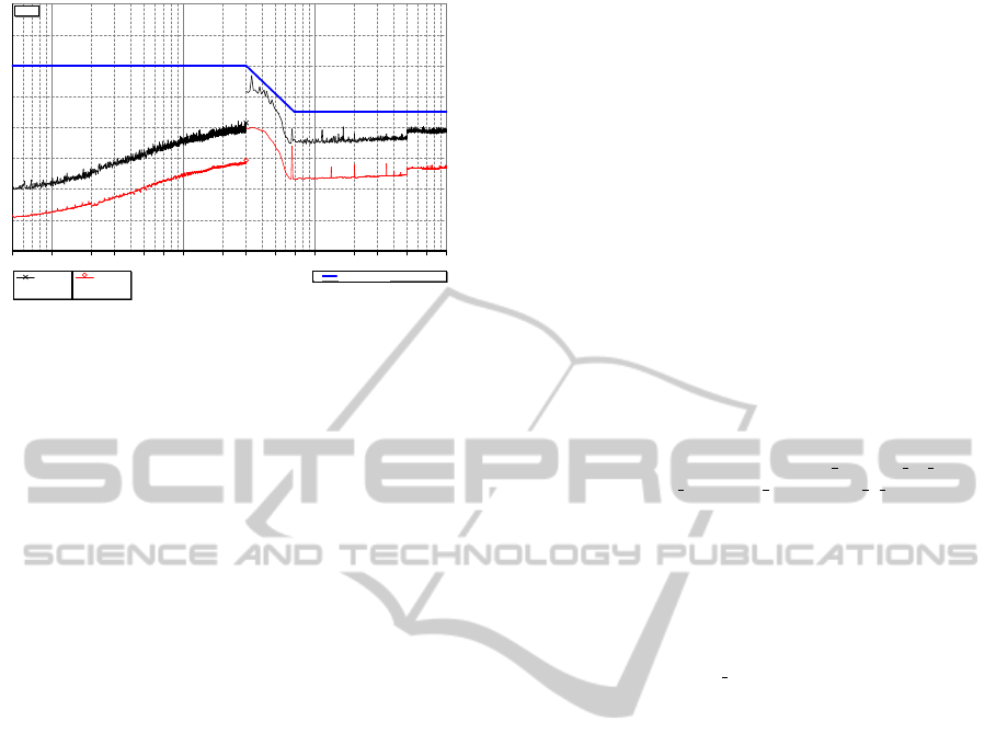
6.4 Results
Figure 4 shows the final result of the measurements.
Like in figure 3 the average and the peak emissions for
the dedicated frequencies can be seen. This time with
running media converters configured as explained in
section 6.2. With regard to the noise level in figure
3, the emission is increasing steadily from 500 kHz
to 30 MHz, where it begins to reach the fundamen-
tal frequency 33,3 MHz, mentioned in section 4. This
is the range of frequencies where the BroadR-Reach
signal filter has its lowest attenuation to let the signal
PECCS2014-InternationalConferenceonPervasiveandEmbeddedComputingandCommunicationSystems
134
Measurement: 13.03.2013 16:19:44
Continental Automotive GmbH / EMC-Laboratory Regensburg
Radiated Emissions / Development Test Result. Not for Sign-Off / TS2
EUT: Techniker Converter Link; HW: ; SW: EMV Link; DUT #
Manufacturer: Continental Automotive GmbH
Setup: Stripline-setup (2 x LISN)
Performers: Mr. Ndounokon; Mr. Eglmeier, Mr. Degueldre
Operating mode: EQI Messung
Test plan: BMW BDC EMV Testplan Version 04
Comment: 10V Vbat ohne Battery; ein BR-Reach und ein optical ethernet
-No- -Receiver- -Detector(s)- -fstart [Hz]- -fstop [Hz]- -fstep [Hz]- -IF-BW [Hz]- -dwell time- -Transducer-
1 FFT ESCS30, 9kHz Pk Av 500k 2M 3,1k 9k 200ms [none]
2 FFT ESCS30 Pk Av 2M 30M 3,1k 9k 200ms [none]
3 FFT ESCS30 Pk Av 30M 1G 49k 120k 100ms [none]
-30
-20
-10
0
10
20
30
40
50
500k 1G [Hz]1M
2M 3M 5M 7M
10M
20M 30M 50M 70M
100M
200M 300M 500M 700M
GS 95002 SL PK 1
Peak
11,5 dBµV
f= 30 MHz
Average
-1,3 dBµV
f= 30 MHz
Peaks at acceptance limit
Limit1 Limit2 Limit3 Limit4
No. Freq [Hz] Peak Avg CISPR-QP - Type
p nb
- - -
3 33,153M 26,8 10 - - BB 28,1 - - -
3 37,567M 23,2 9,2 - - BB 25,7 - - -
3 40,202M 21,4 9,1 - - BB 25,1 - - -
3 40,518M 22,1 8,8 - - BB 24,6 - - -
3 41,518M 20 8,5 - - BB 23,9 - - -
3 42,567M 21,7 7,9 - - BB 23,7 - - -
3 43,567M 19,8 7,3 - - BB 23 - - -
3 46,518M 19 5,6 - - BB 22 - - -
3 47,567M 17,8 5,3 - - BB 21,7 - - -
File: D:\-=MAP=-\WISES\EMV-Messungen\TS2_RE Stripline\mes\BDC-BroadR_130313S2sAap02.mes
[dBµV]
Figure 4: Result of the emission measurement. Blue: Limit
line from GS 95002; Black: Peak detector result; Red: Av-
erage detector result.
pass. The frequencies over 70 MHz follow exactly the
noise floor measurement what lets assume that the fil-
ter cuts of everything from here. Over the whole mea-
surement there was no exceed of the limit line. Thus
the signal of the Technica/tinytron media converter is
GS 95002 conform with regard to copper bound emis-
sion.
7 SUMMARY AND
CONCLUSIONS
In this paper a test setup was built up to measure
the copper bound emission of the BroadR-Reach con-
nection between two identical media converters from
Technica/tinytron. The measurement receiver settings
and the limit lines were taken from the BMW Group
Standard 95002.
The results in figures 3 and 4 show that there was no
limit line exceeded during the tests. That makes the
Technica/tinytron media converters GS 95002 confor-
mant in case of copper bound emissions. Addition-
ally there is no difference between the noise level
and measurements at frequencies higher than 70 MHz
which is an indicator, that the signal filter does cut off
the internal frequencies of the converter reliably.
That leads to the conclusion, that the Tech-
nica/tinytron media converters itself do not add any
distortions to the test setup and can be used for inside
EMC chamber use. But the measured emissions are
relatively close to the limit line at about 40 MHz. A
change in the cable, connector or in the filter topol-
ogy, for example when node A and B are different,
eg node B is a DUT, could cause a signal reflection.
Thus an exceedance of the limit lines could be pos-
sible. Hence a further investigation has to be made
when the filter values or topologies are changed in
the setup. Optical-to-BroadR-reach media converters
with matching filters to the DUT will be important for
every future evaluation of ECUs.
The research leading to these results was supported
by Regionale Wettbewerbsfaehigkeit und Beschaef-
tigung, Bayern, 2007-2013 (EFRE) as part of the
SECBIT project (http://www.secbit.de)
REFERENCES
BMW Group (2004-10). BMW Group Standard 95002.
Broadcom (2013-05). BroadR-Reach Phyiscal Layer.
http:// www.broadcom.com/products/Physical-Layer/
BroadR-Reach-PHYs.
Bruckmeier, R. (2010). Ethernet for Automotive Applica-
tions. Freescale Technology Forum, Orlando.
Continental Engineering Services (2013-07). Conti-
nental Engineering Services. http://www.conti-
engineering.com/www/engineering services de en/
themes/ electric electronic architecture 1 en.html.
OPEN Alliance (2013-05). One Pair Ethernet.
http://www.opensig.org.
Strobl, M. (2012-10-25). Electromagnetic emissions mea-
surements and powerline communication improve-
ments.
Technica Engineering (2013-07). Technica Engi-
neering media converters. http://www.technica-
engineering.de/?page id=1701.
Verdon, A. and Tazebay, M. (2013-09). Broadr-reach archi-
tecture.
ElectromagneticEmissionofanOptical-to-BroadR-ReachConverter
135
