
Compensation of the Antenna Polarization Misalignment in the RSSI
Estimation
D. Polese, L. Pazzini, A. Minotti, L. Maiolo and A. Pecora
Consiglio Nazionale delle Ricerche - Istituto per la Microelettronica e Microsistemi (CNR-IMM),
Via del Fosso del Cavaliere 100, 00133, Roma, Italy
Keywords: Wireless Sensor Network, ZigBee, RSSI, Polarization Angle, Accelerometer, Inclinometer Sensor, Indoor
Localization.
Abstract: The diffusion of wireless sensor networks has allowed the development of a plethora of indoor localization
algorithms based on these technologies. Also if several radio signal features have been exploited in order to
estimate the position, the Received Signal Strength (RSS) is probably the most used. RSS depends, in
addition to the distance, also on multipath transmission, barriers and non-idealities of antenna. Differences
between ideal and real omnidirectional transmission patterns or polarization angle misalignment can
strongly affect the RSS value impairing the following localization algorithm.
In this paper, an algorithm to compensate the dependence of the RSS on the angle among the antennas is
proposed and tested. The experimental results prove the goodness of the approach and the possibility of
using this algorithm to minimize the dependence of RSS from the tilting angle among the nodes of a
localization sensor network.
1 INTRODUCTION
In recent years, the study of localization problems
have gained both commercial and academic interest.
Indeed, the direct use of a navigation system is today
a daily experience using smartphones, tablets and
car navigation systems.
Localize an object or a person means to link
them to a point on a map. In order to perform this
connection the distances of the object from reference
points have to be known. The localization
algorithms can be distinguished in outdoor and
indoor localization if the localized object or person
is mapped outside or inside a building respectively
(Franceschini et al., 2009, Curran et al., 2011).
The outdoor localizations are generally based on
satellite technologies: the most famous is probably
the Global Positioning System (GPS) (Hofmann-
Wellenhof et al., 1993) developed by the United
States Department of Defense, but also other
countries have developed similar technologies. For
example, European Union has recently started to
realize its own positioning system called GALILEO
again based on satellite signals (Hein et al., 2000).
Unfortunately the satellite technologies are limited
to free space, since satellite signals cannot generally
cross building walls. However, beside the satellite
technologies, in the last years, thanks to the
increasing spread of smartphones, diverse
applications based on mobile phone signals have
become accessible.
Indoor localization is generally based on radio
wireless technologies, even if localization system
based on Infrared and Ultrasound technologies have
been also developed (Randell et al., 2001).
However, also if different radio signal features or
technologies can be used, and different
environments can be taken into consideration,
triangulation methods are almost the only way to
estimate the object position. In particular, the
triangulation algorithms can be classified in
lateration and angulation algorithms (Hightower et
al. 2001). Lateration algorithms use the distances
among the object and at least three non-collinear
reference anchors to evaluate the relative position.
On the other hand, angulation algorithms use three
angle measurements performed on two anchors at a
known distance to obtain an estimation of the
relative position of the object. The angles have to be
measured in respect to the same reference, for
example the magnetic North. Generally, angulation
algorithms need more complex hardware than
263
Polese D., Pazzini L., Minotti A., Maiolo L. and Pecora A..
Compensation of the Antenna Polarization Misalignment in the RSSI Estimation.
DOI: 10.5220/0004810202630267
In Proceedings of the 3rd International Conference on Sensor Networks (SENSORNETS-2014), pages 263-267
ISBN: 978-989-758-001-7
Copyright
c
2014 SCITEPRESS (Science and Technology Publications, Lda.)

lateration ones to measure the angle of seeing
between anchors and nodes, for example an array of
antennas. Lateration algorithms, instead, need
simpler hardware to evaluate the distance among the
nodes, since it can be based on propagation time
and/or signal strength. In particular, Time of Arrival
(TOA), Time Difference of Arrival (TDOA) and
Received Signal Strength (RSS) are well known
signal parameters used in indoor localization (Liu et
al., 2007, Patwari et al., 2005). Among these,
methods based on the RSS value have gained
growing interest, since RSS is probably the most
accessible transmission parameter that can be used
to estimate the distance between two nodes.
Furthermore, to measure the RSS, the more recent
RF transceivers have an integrated module that
estimates the RSS, the Received Signal Strength
Indication (RSSI). ZigBee protocol 802.15.4-2012
uses RSSI as indication data standardizing also the
RSSI measurement (IEEE 802.15.4f™-2012).
Moreover, its large use is also justified by the simple
equation that connect RSSI with distance (Aamodt,
2011):
10
10 log
R
SSI n d A
(1)
Where n is the signal propagation constant, d is the
distance between sender and receiver and A is the
RSSI at a distance of one meter. n and A are two
parameters that depend on the medium and also by
the angle between the antennas. The easy use of
RSSI value in indoor environment is traded off with
several error factors as multipath, presence of
barriers between source and receiving antenna, angle
among the antennas.
Even if omnidiretional antennas are used, little
changing of angle between the antennas could give
large variation of the RSSI value and then larger
error on the measurement of the distance. These
variations are produced by the not ideality of the
omnidiretional antennas and by the misalignment of
polarization angle.
Previous works have shown the importance of
these problems in the power transmission. In
particular, Wadhwa et al. (Wadhwa et al., 2009)
have deeply investigated how the polarization
misalignment reduces the power transmission of a
wireless sensor network and they propose an
algorithm to estimate the relative antenna orientation
and find the low power transmission path. Whereas,
Huang (Huang, 2009) has shown that it is possible to
improve the localization performance also in
presence of antenna polarization losses with a better
estimation of the parameter n and A of equation 1.
Instead of reducing the effects of the polarization
losses in the RSSI estimation, in this paper, we
estimate the tilting angle between a static anchor
antenna and a moving antenna by means of an
accelerometer and then we use it to correct the
measured RSSI value. In this way, improving the
accuracy on the RSSI measurements it is possible to
improve also the accuracy on the anchor to mobile
node distance measurements (see equation 1), thus
enhancing the localization algorithms based on
lateration of RSSI signals.
The remainder of this paper is organized as
follows: in section 2 the algorithm of compensation
is presented. In section 3 the experimental set-up and
the results are shown. Finally, section 4 concludes
the paper.
2 RSSI LOSS COMPENSATION
The transmitted power between a transmit and
receive antenna depends also on the polarization
direction and spatial orientation. In particular,
misalignment polarization angle between antennas is
a well-known power loss factor that, for linearly
polarized antenna, can be easily estimated. Indeed,
knowing the relative misalignment angle between
the antennas (
, the polarization mismatch loss can
be evaluate using the following equation (Kishk,
2009) :
_ 20 log(cos )[ ]
R
SSI LOSS dBm
(2)
Therefore, the real RSSI, i.e. the RSSI that should be
measured without misalignment error can be
estimated using the following relation:
_
EM
R
SSI RSSI RSSI LOSS
(3)
where
E
R
SSI
is the effective RSSI and
M
R
SSI
is the
measured RSSI. It is also important to point out that
the RSSI_LOSS value is always negative.
In order to estimate the polarization angle
between two antennas an inclinometer can be used.
In presence of movements where the acceleration is
much lesser than gravity acceleration, accelerometer
can be used as an inclinometer sensor (Luczak et al.,
2006). Inclinometer sensors based on accelerometers
use the known direction of the gravity acceleration
and the direction of the current gravity acceleration
in its local reference system to estimate the tilting
angle. Using this sensor it is possible to evaluate the
tilting angle respect the vertical axis.
Figure 1 shows a schematic representation of the
accelerometer, the three axis are highlighted by the
reference system.
SENSORNETS2014-InternationalConferenceonSensorNetworks
264
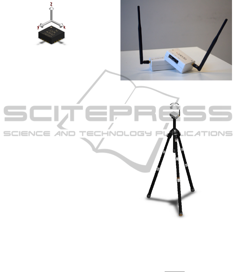
Figure 1: In figure a tri-axial accelerometer is shown.
Placing an inclinometer on a mobile antenna is
possible to estimate the orientation of the antenna
respect to the vertical, thus evaluating the angle
between the vertical axis and the antenna axis.
Furthermore, knowing also the anchor antenna
orientation respect to the vertical it is possible to
estimate the relative orientation of the antennas.
3 EXPERIMENTAL RESULTS
In order to verify the algorithm, two commercial
wireless sensor nodes Z1 Zolertia are used (Zolertia
Z1). Each node is equipped with an external
omnidirectional pigtail antenna (see figure 2). In this
configuration, one wireless node is used as an
anchor node, while, the other wireless node is used
as a moving node.
Several measurements of the RSSI have been
performed at different distances and several tilting
angles. During the measurements the mobile node is
firmly bound to the head of a tripod that can be
easily tilted in each direction (see Figure 3). At the
same time the anchor node continuously acquires the
data packets sent from the mobile node. The data
packet has a payload composed by the three axial
components of the acceleration. The RSSI value is
measured by the anchor node according to CC2420
specification (CC2420). Each measurement is
performed tilting continuously several times the
mobile node around two perpendicular directions as
figure 3 shows. Finally, acceleration and RSSI
values are sent to PC in order to perform the
following compensation algorithm.
The effective RSSI value is calculated using the
equation 2, but limiting the maximum loss value to
AM
RSSI RSSI
in order to take into consideration
the non ideality of the system, i.e. the transmitted
power between two orthogonal linearly polarized
antennas is not zero. For each distance three
repetitions are performed.
In order to evaluate the goodness of the
compensation,
the standard deviation of the raw and
Figure 2: The two wireless sensor nodes equipped with an
external antenna.
Figure 3: The figure shows the mote firmly bound on the
head of the tripod. The two arrows show the two
orthogonal rotations performed during the measurements.
corrected RSSI are compared. Moreover, the
improving of the RSSI estimation is evaluated by
means of the following standard deviation ratio:
Σ
σ
σ
(3)
Greater ratio means a better precision of the
measurements. Table 1 shows, for each distance, the
mean and standard deviation of the measured and
corrected RSSI. In particular, the parameter shows
that using the compensation algorithm it is possible
to increase the precision of the RSSI estimation i.e.
to reduce the standard deviation of the
measurements.
CompensationoftheAntennaPolarizationMisalignmentintheRSSIEstimation
265
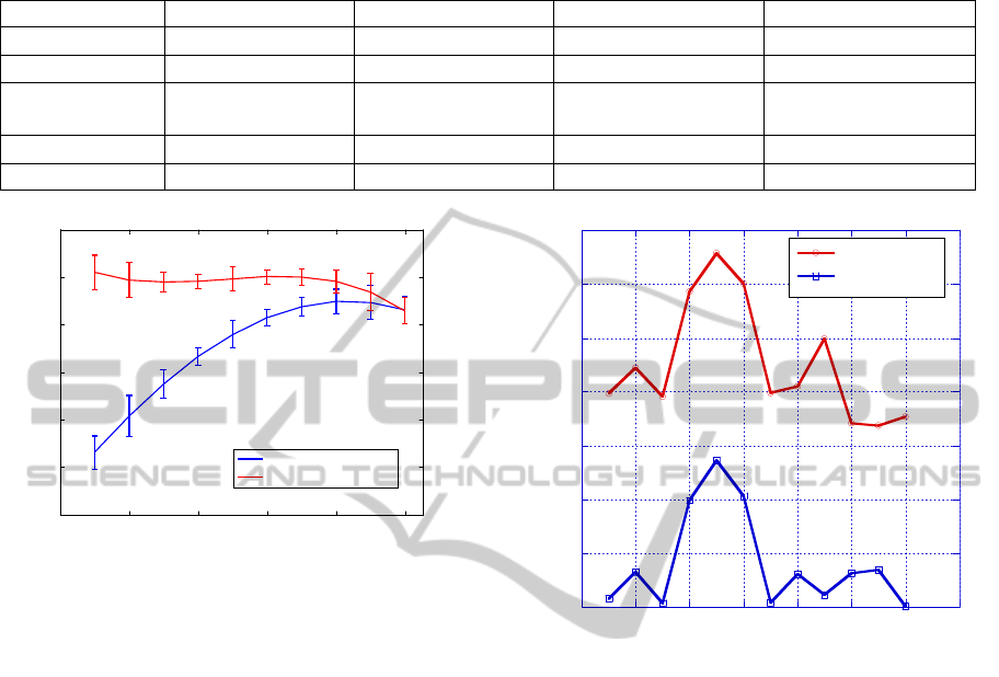
Table 1: In this table the mean values and standard deviation of the RSSI for several distances measurements are reported.
RSSI
M
is the measured RSSI value, RSSI
E
is the effective RSSI. μ(·) is the mean and σ(·) is the standard deviation. For each
distance, the standard deviations among the different measurement repetitions are also reported.
Distance [m] 1 2 4 6
RSSI
M
)[dBm]
2.5931 0.0918 3.9685 0.9025 10.3634 0.2591 13.9524 0.2384
RSSI
M
)[dBm]
5.8428 0.3043 7.0881 0.1037 5.3859 0.3793 4.8319 0.5009
RSSI
E
)[dBm]
6.4558 0.1994 0.0826
0.9147
5.9072 0.6053 10.0582 0.1136
RSSI
E
)[dBm]
4.5586 0.4693 5.4023 0.2295 5.2761 0.2435 4.1028 0.6833
Σ
1.2817 1.3121 1.0208 1.1777
Figure 4: In the figure the mean profile of the measured
RSSI is compared with the mean profile of the
compensated RSSI during several tilting. The measured
RSSI changes with the cosine of the tilting angle whereas
the compensated RSSI is almost unchanged.
Figure 4 shows an example of a RSSI measurement
when the mobile node is tilted several times. The
measured RSSI changes with the cosine tilting angle
whereas the compensated RSSI is almost unchanged,
this means that the algorithm is able to reduce the
losses due to the antenna misalignment error.
Figure 5 shows another evidence of better
evaluation of the RSSI using the proposed
algorithm. In this figure, the accuracy of the
estimated RSSI value is evaluated sketching the
differences among the RSSI.
measured when the polarization effect is negligible
(cos( ) 0.99)
, thereafter called RSSI aligned (
A
RSSI
), and the mean value of the corrected and
raw RSSI.
A
RSSI
can be considered the correct
RSSI value, since it is the RSSI value measured
when the antennas are aligned. The average values
of the RSSI corrected and raw are performed on the
whole set of the acquired values during the
measurement. In particular, the RSSI is evaluated in
an almost continuous range of angle values between
approximately 0 to rad.
0
1
2
3
4
5
6
7
02468101214
|RSSI
A
- RSSI
M
|
|RSSI
A
- RSSI
E
|
RSSI error [dBm]
Measure number
Figure 5: Absolute difference between the RSSI measured
with zero angle of tilting and the mean value of the RSSI
measured and corrected for all the rotations. Correcting
the RSSI it is possible to reduce the mean error in the
RSSI evaluation of almost 2 times.
Values near to zero of the previous difference
(
) mean that the compensation
algorithm is able to correctly counterbalance the
power loss effect depending on the antenna
misalignment. It is worth of noting that this
difference is always lesser than the difference with
the raw values (
AM
RSSI RSSI
). Moreover, for the
most part of the measurements this difference is
lesser than one dBm whereas uncorrected difference
is always greater than three dBm. These results
suggest that this algorithm can potentially minimize
the antenna misalignment errors.
4 CONCLUSIONS
In conclusion, a simple algorithm to reduce the
effect of the tilting angle between antennas has been
0 0.2 0.4 0.6 0.8 1
-15
-10
-5
0
5
10
15
Cosine of tilting angle
RSSI [dBm]
Measured RSSI
Compensated RSSI
SENSORNETS2014-InternationalConferenceonSensorNetworks
266

shown. A common accelerometer utilized as tilting
sensor is exploited to estimate the RSSI loss that is
used to correct the measured RSSI. In this way, the
proposed algorithm can evaluate the misalignment
angle between two antennas in order to compensate
the transmission losses.
The algorithm has been tested using two
commercial Wireless Sensor Nodes and the results
have shown that it is able to reduce the dependence
on the tilting angle of the RSSI at least by a factor 2.
ACKNOWLEDGEMENTS
This research was partially supported by the
Flagship Project "Factory of the Future"
FACTOTHUMS of the National Research Council.
REFERENCES
Franceschini, F., Galetto, M., Maisano, D., &
Mastrogiacomo, L. (2009). A review of localization
algorithms for distributed wireless sensor networks in
manufacturing. International Journal of Computer
Integrated Manufacturing, 22(7), 698-716.
Curran, K., Furey, E., Lunney, T., Santos, J., Woods, D.,
& McCaughey, A. (2011). An evaluation of indoor
location determination technologies. Journal of
Location Based Services, 5(2), 61-78.
Hofmann-Wellenhof, B., Lichtenegger, H., & Collins, J.
(1993). Global Positioning System. Theory and
Practice. J. Springer, Wien (Austria), 1993, 347 p.,
ISBN 3-211-82477-4, ISBN 0-387-82477-4 (USA)., 1.
Hein, Günter W. "From GPS and GLONASS via EGNOS
to Galileo–Positioning and Navigation in the Third
Millennium." GPS Solutions 3.4 (2000): 39-47.
Randell, C., & Muller, H. (2001, January). Low cost
indoor positioning system. In Ubicomp 2001:
Ubiquitous Computing (pp. 42-48). Springer Berlin
Heidelberg.
Hightower, J., & Borriello, G. (2001). Location sensing
techniques. IEEE Computer, 34(8), 57-66.
Liu, H., Darabi, H., Banerjee, P., & Liu, J. (2007). Survey
of wireless indoor positioning techniques and systems.
Systems, Man, and Cybernetics, Part C: Applications
and Reviews, IEEE Transactions on, 37(6), 1067-
1080.
Patwari, N., Ash, J. N., Kyperountas, S., Hero III, A. O.,
Moses, R. L., & Correal, N. S. (2005). Locating the
nodes: cooperative localization in wireless sensor
networks. Signal Processing Magazine, IEEE, 22(4),
54-69.
IEEE 802.15.4f™-2012 - IEEE Standard for Local and
metropolitan area networks-- Part 15.4: Low-Rate
Wireless Personal Area Networks (LR-WPANs)
Amendment 2: Active Radio Frequency Identification
(RFID) System Physical Layer (PHY.
Aamodt, K., (2011) Chipcon Products from Texas
Instruments, Application Note AN042 (Rev. 1.0).
Wadhwa, M., Song, M., Rali, V., & Shetty, S. (2009,
August). The impact of antenna orientation on
wireless sensor network performance. In Computer
Science and Information Technology, 2009. ICCSIT
2009. 2nd IEEE International Conference on (pp. 143-
147). IEEE.
Huang, X. (2009, February). Antenna polarization as
complementarities on RSSI based location
identification. In Wireless Pervasive Computing,
2009. ISWPC 2009. 4th International Symposium on
(pp. 1-5). IEEE.
Kishk, A. A. (2009). Fundamentals of Antennas. Antennas
for Base Stations in Wireless Communications.
Luczak, S., Oleksiuk, W., & Bodnicki, M. (2006). Sensing
tilt with MEMS accelerometers. Sensors Journal,
IEEE, 6(6), 1669-1675.
Zolertia Z1 http://www.zolertia.com/products/z1.
CC2420 (2013) 2.4 GHz IEEE 802.15.4 / ZigBee - ready
RF Transceiver, SWRS041c datasheet, http://
www.ti.com/general/docs/lit/getliterature.tsp?genericP
artNumber=cc2420&fileType=pdf.
CompensationoftheAntennaPolarizationMisalignmentintheRSSIEstimation
267
