
Designing CAx-process Chains
Model and Modeling Language for CAx-Process Chain Methodology
Pascal Schug and Alexandr Kotlov
Fraunhofer Institute of Production Technology IPT, RWTH Aachen University, Steinbachstraße 17, Aachen, Germany
Keywords: CAx, Process, Chain, Model, DSL.
Abstract: Product development and production processes are supported by software systems during the development
and planning phases. The usage of these software tools during or prior to and post the different process steps
is called CAx-processes. The combination of these CAx-processes form process chains, also known as
CAx-process chains (CAx-PCs), which mirror the production processes virtually. The content of this paper
introduces a solution for designing the software chains in conformity to the methodology for evaluation,
analysis and optimization of CAx-PCs. The solution includes the definition of DSL expressing the model
for CAx-PCs and the software prototype “CAx-process chain designer” for deriving the alternatives of
CAx-PCs from the expressed model.
1 INTRODUCTION
Typically, product development starts with a
conceptual idea and ends up as a final product.
However, the path between the conceptual idea and
the final product is complex because of the several
obstacles such as product complexity, manufacturing
technology constraints as well as the time and
resource limits. Therefore, the problem of the
increasing complexity of products was addressed by
various computer aided technologies also known as
CAx-technologies.
CAx-technologies mirror the traditional and
general product development. According to Werner
Dankwort’s paper (Werner Dankwort, 2004),
product development consists of three main phases:
creative, conceptual and engineering phase. These
phases are supported by different information
systems. Usually, these information systems are
called CAx-systems. CAx is an umbrella term for
computer aided processes and systems and their
respective technologies. For instance, CAD stands
for computer aided design and CAM for computer
aided manufacturing. In addition, different
simulation software systems are involved in product
development. As a result, CAx-technologies offer
advantages such as reduced expenses, resources and
time. This is caused by a virtual representation of
processes within the product life cycle, which allows
a quick and simple detection of deviations and errors
within processes. The implementation of CAx-
technologies is one of the factors that helps to
decrease the necessary time and costs of iterations in
the development, planning and optimizing phases.
(Brecher, 2006)
Hence, the deployment of CAx-based product
development is especially suitable in the case of
complex products and processes. This induces
companies to use a variety of specialized software
systems before and during the production.
1.1 CAx-process Chains
The CAx-based production includes many virtual
processes during the product life cycle phases,
which form a CAx-process chain (CAx-PC)
(Bullinger, 2008). A simplified case of a CAx-PC
for turbine blade production is illustrated in
Figure 1. The CAx-process chain starts with
designing of the turbine blade in CAD tools. This
CAD model is transferred to the process preparation
software which includes manufacturing and
verification tools (CAM). CAM tools create
toolpaths based on component geometry for milling,
which are represented in machine independent NC-
Code. Afterwards these toolpaths are verified by
various software tools with different analysis
focuses. The NC-Code is transfered to NC-Programs
for specific machines within the post processing
step. Finally, these specified NC-Programs are
724
Schug P. and Kotlov A..
Designing CAx-process Chains - Model and Modeling Language for CAx-Process Chain Methodology.
DOI: 10.5220/0005054507240733
In Proceedings of the 11th International Conference on Informatics in Control, Automation and Robotics (ICINCO-2014), pages 724-733
ISBN: 978-989-758-040-6
Copyright
c
2014 SCITEPRESS (Science and Technology Publications, Lda.)
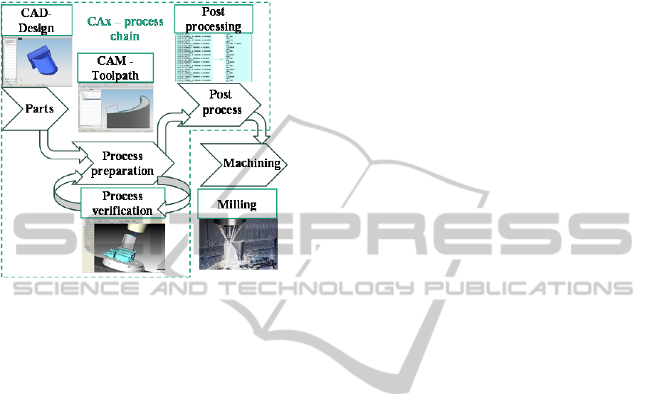
interpreted by the machine control as actual physical
movements of machine tools. This example
illustrates a trivial case of deployment of CAx-
technologies in production.
Figure 1: CAx-process chain, adapted from (Minoufekr,
2013).
When CAx-processes are combined to one process
chain, gaps between the process steps and systems
occur. These gaps among other factors hinder the
necessary information for establishing a robust
process chain. (Brecher, 2006).
In order to establish a robust process chain, a
methodology is introduced to capture the CAx-PCs
(Schug, 2014). This methodology offers solutions
for deriving an optimized process chain by creating
alternatives for the existing process chain. Due to the
specific nature of the CAx-PC evaluation, analysis
and optimization methodology (CAx-PC
methodology), a suitable implementation is needed.
This paper presents the CAx-PC methodology
and it’s corresponding implementation. This
involves the development of a software application
and a model to design CAx-PCs according to the
methodology.
2 BACKGROUND
This section discusses the methodology for
capturing CAx-PCs. According to this methodology,
the software requirements for a software application
designing CAx-PCs are derived.
2.1 Capturing CAx-process Chain
For data tranfer between different software systems,
suitable interfaces need to be defined, which tranfer
all necessary information between the systems. An
interface in this case is the connection between
software which defines and guarantees combination
ability (Ludewig, 2007). Most of the information
losses can be found and fixed at the data level.
(Klocke, 2004)
Because of the individual combination of
different CAx-tools for each process a complete data
transfer via interfaces is not always guaranteed.
Different data formats or software settings and
requirements are the reason for the loss of data and a
main problem within the CAx-PC. During the data
transfer between systems a number of irreversable
conversions take place, such as the loss of tolerances
or dependencies, which hinder a continuous data
flow (Brecher, 2006). For example, information loss
may occur during the data exchange between
different CAD systems which use diverse data
formats to represent parts. Even neutral data formats
like STEP (Standard for the exchange of product
model data) do not transfer all the needed
manufacturing information (Sääski, 2005).
The CAx-PC methodology captures the current
state of the CAx-PCs which represents the CAx-PCs
during the various phases of the manufacturing
process. It is also extended by a metric based
approach for calculating different evaluation criteria,
which are used to evaluate the entire process chain.
Therefore, different process types are defined and
represented by their individual process
characteristics. For example, a CAD-process has
characteristics such as evaluation criteria (duration,
cost, quality, resource efficiancy), or other
characteristics that describe the process such as
interface definitions, software information or input
and output information. The CAx-processes are
connected by data flows. Each CAx-process has
CAx-products as outputs. In case of a CAD-process,
the product has specialized characteristics such as
geometry, file structure or additional information of
the CAD-model. Within the metrics, these different
characteristics and the related values are used for the
evaluation criteria such as costs, time, quality, and
resource efficiency of the processes and the process
chain. The customized weighting of these criteria
enables the methodology to react on the changing
requirements or boundary conditions in the CAx-PC.
Based on the captured state of the CAx-PC an
additional analysis of the process chain takes place.
This analysis considers the processes as well as the
DesigningCAx-processChains-ModelandModelingLanguageforCAx-ProcessChainMethodology
725
overall CAx-process chain. The analysis operates on
the captured characteristics and the values via
metrics that calculate the evaluation criteria of each
process as well as the entire process chain. During
this analysis phase, optimization potentials within
the CAx-PC are categorized into potentials which
are related to software, interfaces, organization,
strategy and non-standard processes.
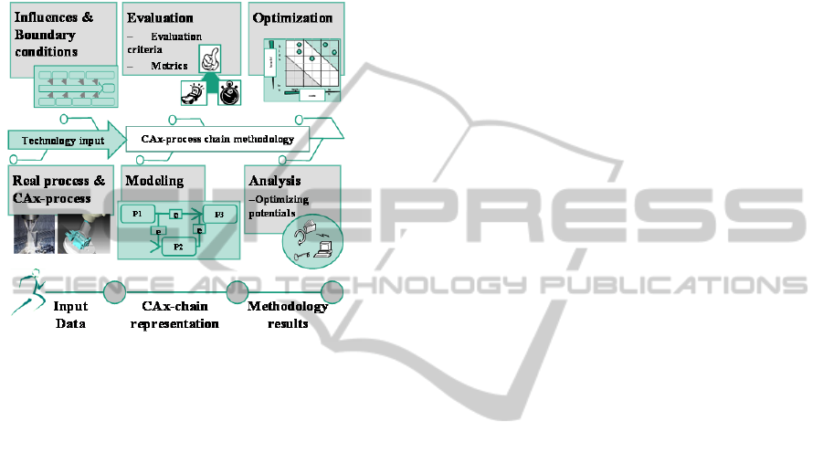
Figure 2: CAx-PC methodology (Schug, 2014).
The optimization potential depends on the occurring
conflicts within the chain and the possible outcome
of using alternative processes or process chains.
Based on this categorization and on the evaluation,
the optimization steps are derived.
This methodology is pictured in Figure 2.
Boundary conditions and influences are company
preferences which depend on the existing real
processes and the CAx-processes such as time and
cost demands as well as fixed conditions such as
installed machines or software systems. This
information is used as an input for the methodology
during analysis. As a result of this methodology,
opitmizing potentials can be identified and selected
based on a Cost-Benefit analysis.
2.2 Software Requirements
To utilize the methodology, a software application
(tool) is needed for designing CAx-PCs. For this,
software requirements are established which capture
the essence of the methodology.
According to Wiegers, well defined requirements
provide the foundation for quality software
(Wiegers, 2000). To ensure that, Wiegers describes
ten requirement traps and the solutions to avoid
these traps. In this description, three levels of
requirements are offered. The top level contains
business requirements which represent high-level
objectives of organizations or required systems or
products. The second level deals with user
requirements. The final third level includes specific
software functional requirements which are derived
from the use cases and describe specific software
behaviors. The functional and nonfunctional
requirements form the software requirements
specification. Based on these notions and the
methodology, the software requirements are defined
for the tool that designs CAx-PCs.
In our case, the business requirement states that a
tool is required for designing CAx-process chains
according to the methodology. With such tool, the
user, who is a CAx-expert, is able to derive an
optimized process chain by designing alternatives of
process chain. The tool has several user
requirements which derive respective functional
requirements from the usage scenarios or use cases.
The first usage scenario states the user must be
able to design CAx-PCs with the tool. This produces
the first functional requirement that claims that the
tool has to scheme the chains by drawing,
manipulating and editing the CAx-processes within
the designed process chains.
According to the second usage scenario, the user
must perform the evaluation of designed process
chains with the software application. Therefore, the
second functional requirement is calculation, which
implies that the tool has to implement calculations of
the process data to estimate the evaluation criteria
such as costs, time, quality and resource efficiency
of the CAx-PCs. Based on the evaluation criteria,
additional metrics for calculating the process related
characteristics provide an evaluation of the entire
process chain.
The last usage scenario states that the user must
locate optimization potentials within the process
chains. Thus, the third functional requirement is
process analysis, which according to the
methodology, implies that process chains have to be
analyzed for optimization potentials based on
different categories. Also, they have to be compared
with alternative process chains. Therefore, the third
functional requirement claims that the tool has to
compare and analyze processes within the process
chains to identify optimization potentials. Feedback
is the last functional requirement which implies that
the tool has to notify the user about changes of
optimization potentials within the designed process.
To recapitulate, the following software requirements
for the tool designing CAx-PCs have to be applied:
Scheme chains: the tool has to plan the chains
ICINCO2014-11thInternationalConferenceonInformaticsinControl,AutomationandRobotics
726
by drawing, manipulating and editing the
CAx-processes within the designed process
chains;
Calculation: the tool has to implement
calculations of the process data to estimate the
evaluation criteria;
Process analysis: the tool has to compare and
analyze the processes within the process
chains to identify the optimization potentials;
Feedback: the tool has to notify the user
about the changes of the optimization
potentials within the designed process chains.
In practice, there exist several diagramming
tools, which can be considered for designing process
chains. Therefore, we will review some existing
tools in the following section.
2.3 Existing Tools
CAx-experts use various tools to capture process
chains. This section reviews existing tools which
could be used to design process chains. Previously,
software requirements for the tool designing CAx-
PCs were discussed. These software requirements
will be used as comparison criteria to identify an
appropriate tool for designing CAx-PCs according to
the introduced methodology. The comparison
criteria include calculation, process analysis and
feedback. The functional requirement “Scheme
chains” is excluded from the comparison criteria.
Because all reviewing tools are capable to scheme
the chains by drawing, manipulating and editing the
CAx-processes within the designed process chains.
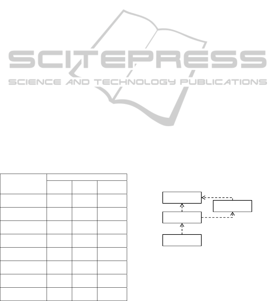
Table 1: Overview of tools.
Tool
Functional requirements
Calcu-
lation
Process
analysis
Feedback
Visual Paradigm
(visual-paradigm.com)
not
explicit
yes,
manual
no
MS Visio
(office.microsoft.com)
not
explicit
yes,
manual
no
Aixperanto
(wzl.rwth-aachen.de)
not
explicit
yes,
manual
no
Activiti
(activiti.org)
no
yes with
reports
no
ARIS Express
(activiti.org)
no yes no
ADONIS
(boc-group.com)
yes yes no
MagicDraw
(nomagic.com)
no yes no
Umodel
(altova.com)
no
not
explicit
no
Table 1 provides examples of several diagramming
and modeling tools and shows how the different
requirements are fulfilled in regard to the CAx-PC
methodology. The demonstrated tools in Table 1
satisfy some functional requirements for designing
CAx-PCs according to the introduced methodology.
As indicated in Table 1, all tools lack feedback.
Besides, only half of the tools are able to implement
calculations with the process data, and the majority
depends on the external tools. Hence, an alternative
tool needs to be developed to satisfy the software
requirements. The first prototype of an alternative
tool will be introduced in the following section 4.2
“CAx-process chain designer”.
For the realization of the tool, a model driven
engineering approach is applied. Thus, a model for
CAx-PCs has to be developed, before implementing
the tool.
2.4 Model Driven Engineering
Model Driven Engineering (MDE) is an approach in
software development. MDE provides an abstract
way to hide the complexity of software by using
models. The core of MDE is a model, which eases
the understanding, specification and maintenance of
complex systems (Hutchinson, 2011).
Bézivin describes relations between a system and
a model in the basic notations of MDE as
demonstrated in Figure 3. According to this
description, a system can be represented by a model.
This system itself conforms to a metamodel and is
expressed by a modeling language (Bézivin, 2005).
Based on these notations, it is possible to identify
key elements such as system, model, metamodel and
modeling language, which are used to obtain the
model for CAx-PCs.
Figure 3: Basic notations, adapted from (Bézivin, 2005).
In the case under consideration, a model for CAx-
PCs will be used as a basis for designing CAx-PC
alternatives for further iterative analyses and
optimization steps.The system that has to be
modeled is CAx-PCs. Additionally, other elements
of the basic notations such as model, metamodel and
conforms to
System
Model
Metamodel
Modeling
language
represented by
represented by
conforms to
DesigningCAx-processChains-ModelandModelingLanguageforCAx-ProcessChainMethodology
727

modeling language need to be defined.
3 RESEARCH AREA
In order to obtain a model for CAx-PCs, the
definition of a metamodel is needed. This section
addresses questions to CAx-PC modeling and
describes solutions for the metamodel and modeling
language.
3.1 Problem Definition and Research
Questions
The implementation of the CAx-PC methodology
requires a development of a software application.
The MDE approach is applied to realize the software
application for designing CAx-PCs. This approach
requires a model for CAx-PCs. The definition of a
model includes the definition of a metamodel and a
modeling languge. In order to model CAx-PCs, the
following steps have to be fulfilled.
Firstly, the model for CAx-PCs has to be
specified.
Secondly, entities and relationships of CAx-PCs
have to be defined in a respective metamodel.
Lastly, the modeling language which expresses
the model needs to be defined.
The following section will describe these steps.
3.2 CAx-process Chain Modeling
In the case under consideration, the purpose of the
modeling is evaluation and analysis of CAx-PCs
according to the CAx-PC methodology. Therefore,
the CAx-PC methodology has to be analyzed to
obtain the necessary information for the definition of
the metamodel and the modeling language.
This section describes the essential concepts for
modeling (section 3.2.1) as well as the metamodel
for CAx-PCs (section 3.2.2) and the modeling
languages (section 3.2.3). A CAx-PC modeling
language will be introduced in (section 3.2.4).
3.2.1 Concepts
To specify the model, the CAx-PC methodology
needs to be taken into account (Schug, 2014).
According to the methodology, a state of the
CAx-PCs has to include technological, evaluative
and analytical information not only for each process
but also for the whole chain. In addition, the
methodology offers structual information for the
CAx-PCs. Based on this information, CAx-PC
definitions are identified as following:
CAx-PC: The CAx-PC unites the CAx-processes
by the data flows which exchange technological
information. In terms of graphs notation, the
processes and data flows are represented by the
nodes and edges.
CAx-process: Each CAx-process has several
individual characteristics depending on the process
type. These characteristics include technical process-
related requirements and attributes for the evaluation
and analysis steps. The process-related requirements
describe for example, interface definitions, software
information or input and output information. The
attributes reflect the evaluation criteria, optimization
potentials and process description. In addition, each
CAx-process produces and consumes CAx-products.
CAx-product: The process type dictates the
characteristics of the CAx-product which are
attributes for the evaluation and product-related
requirements that include the information about the
product which represents the produced output during
a process.
Evaluation step: The evaluation is applied on
the individual processes by calculating different
evaluation criteria such as duration, cost, quality,
and resource efficiency. These evaluation criteria
provide an evaluation of the entire process chain.
Analysis step: The analysis is applied on the
entire CAx-process chain. In this step, the
optimizing potentials are identified as occurring
conflicts within the chain which are related to
software, interfaces, organization, strategy and non-
standard processes.
Optimization step: Based on the information
from the evaluation and analysis steps, the
optimization of CAx-process chains is possible by
designing alternative process chains.
These CAx-process chain definitions specify the
information which has to be represented in the
model.
3.2.2 Metamodel
Based on the obtained information from CAx-PC
definitions, it is possible to identify what has to be
represented by the metamodel. In general, the
metamodel describes entities and relations of a
domain. A metamodel, applied to the system, yields
a model of the system (Bézivin, 2005). Thus, the
metamodel is a basis for the model and modeling
language. Figure 5 illustrates the metamodel for
CAx-PCs. Several entities are identified in this
metamodel such as process, product, attribute and
requirement. A process chain might contain many
ICINCO2014-11thInternationalConferenceonInformaticsinControl,AutomationandRobotics
728
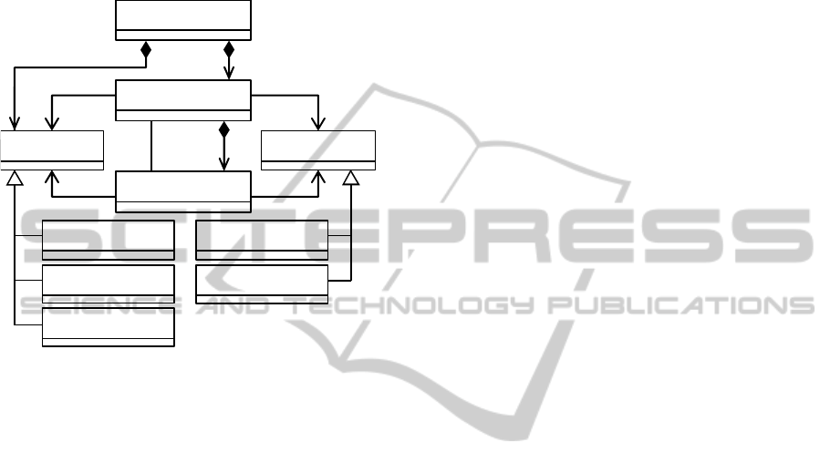
processes and attributes. Besides, each individual
process has many attributes and requirements.
Moreover, each process contains products which are
related to the processes as inputs or outputs. The
requirements can be broadly classified into two
classes i.e. process-related and product-related
requirements.
Figure 5: Metamodel.
The attributes are general, evaluative and analytical
attributes which are necessary for the evaluation and
analysis of process chains.
This metamodel provides definitions for the
modeling languages which expresses the model for
CAx-PCs.
3.2.3 Modeling Language
In order to express the model for CAx-PCs, a
modeling language has to be utilized. For this, it is
necessary to select or define a modeling language to
express the metamodel. Modeling languages are
divided into general-purpose languages (GPL) and
domain-specific languages (DSL).
An example of GPL is Unified Modeling
Language (UML) that is used for general and broad
modeling (OMG, 2005). The notations of UML such
as classes, associations and relations are used for the
description of metamodels. For example, the
metamodel for CAx-PCs in Figure 5 is expressed by
such notations.
DSL is used for domain specific modeling. One
definition of DSL is given in the book about
domain-specific languages by Martin Fowler
(Fowler, 2010). The definition states “Domain-
specific language (noun): a computer programming
language of limited expressiveness focused on a
particular domain”. Further, the author claims that
the basic idea of DSL is to target a particular aspect
or kind of problem in the domain. In the case under
consideration, the problem in the domain is the
modeling of CAx-process chains in conformity with
the methodology. According to Fowler (Fowler,
2008), the DSLs have two main forms such as the
external and internal (embedded). The internal DSLs
are based on the host languages. They use the host
languages in specific ways which resemble some
form of application programming interfaces (APIs).
As per Fowler, the programming languages such as
Ruby, Java and C# are examples of internal DSLs.
Another form of DSLs is the external which has its
own syntax and requires an parser to process such
external DSLs. The examples of the external DSLs
are XML configurations, CSS, Regular Expressions
and domain specific modeling languages (DSMLs).
In order to define modeling language, a couple of
assumptions have to be considered in conformity
with the methodology.
The first assumption is that the model must be
specific. This implies that the model must take into
account the context of CAx-PCs. This includes data
flow of the process steps in the corresponding CAx-
PCs based on information such as CAD data, NC
Programs or analysis data. For example, the CAD-
process contains many part design parameters. These
parameters include many attributes and requirements
such as information regarding the part geometry,
color, physical properties, manufacturing etc
(Feldhusen, 2013). Consequentially, the modeling
language expressing the model should be specific to
these kinds of contexts within the CAx-PC. The
GPL such as UML or UML-based Business Process
Model and Notation (OMG, 2011) can express
various domians. This implies that such languages
are not specific to the domain of CAx-process chain
methodology. As for the DSLs, the definition of
DSL indicates that a DSL is specific to the
respective domain. Therefore, a DSL for modeling
of CAx-PCs will be devoted only to the domain of
CAx-PC methodology.
The second assumption is the level of abstraction
between the problem domain and solution domain.
On one hand, the modeling language should be
abstract from the complexities of the software
application. On the other hand, the model expressed
by the modeling language should be easily
integrated into the software application which will
used to derive CAx-PC alternatives from the model.
In his work, Jackson describes the differences
between the domain idea and the program code. He
concludes that each aspect has different experts,
input 0..*
0..* output
0..*
Chain
Process
Product
1..*
*
Requirement
General Process-related
Evaluative Product-related
Analytical
Attribute
0..*
0..*
0..*
1..*
DesigningCAx-processChains-ModelandModelingLanguageforCAx-ProcessChainMethodology
729
ways of thinking and languages for the domain
description (Jackson, 1995). As a result, the domain
idea is interpreted several times. Kelly S. et al.
explain the transition of the domain idea to the
finished product in domain-specific modeling
(Kelly, 2000). The Figure 6 illustrates the possible
bridges from the problem (domain idea) to the
solution (a finished product or software application).
Figure 6: Moving from the problem domain to solution
domain, adapted from (Kelly, 2000).
In the domain specific modeling, a domain model
does not require mapping of the problem because the
solution for the problem is expressed by respective
DSL that uses the problem domain terms. This raises
the level of abstraction and narrows the abstraction
gap between the problem domain and the solution
domain. In comparison, a model expressed by GPL
such as UML requires, solving of the problem in the
domain terms first and then mapping the solution to
the model. Still, the domain model expressed by
DSL requires generation of code or reuse of existing
components. However, the generation of code is a
tedious task. Fortunally, this can be done with the
help of tools for DSL definition which will be
discussed in the section 4 “Implementation”.
As discussed above, a DSL offers benefits such
as a higher abstraction and usage of domain
concepts. These benefits provide the advantages in
the quality of the model by involving the domain
experts in the communication with the actual domain
model in their language. Kosar et al. conducted the
empirical study to compare GPLs and DSLs. The
results of the study proves the advantages and
superiority of DSLs over GPLs in the cognitive
dimensions such as closeness of mappings,
diffuseness, error-proneness, role-expressiveness,
and viscosity (Kosar, 2010).
Based on this, a DSL will be used for expressing
the model for CAx-PC. Therefore, a DSL for CAx-
PCs must be defined.
3.2.4 CAx-process Chains Modeling
Language
Fowler provides guidelines for the definition of a
new DSL (Fowler, 2005). The first step is to define
abstract syntax which is a scheme of abstract
representations. The next step is to define editing
environments for the language. The last step is to
define semantics for the language by defining a
generator to interpret abstract representations
(Fowler, 2005). Based on this, we recall the basic
notations from section 3.2.1 “Concepts” to update
basic notations as it illustrated in Figure 7.
Figure 7: Modeling with DSL, based on (Bézivin, 2005).
According to this updated description, a CAx-PC
can be represented by a model. The model conforms
to a metamodel which defines an abstract syntax of
DSL. The abstract syntax describes concepts and
relationships of a model independently from any
representations. The abstract and concrete syntaxes
of DSL express the model. The concrete syntax of a
DSL can be specific, textual or graphical. The
meaning of concepts and relationships is defined in
the semantics of a DSL which is used for a code
generator that interprets representations of DSL. The
listing below describes the model for CAx-PCs
which is expressed by the CAx-PCs modeling
language.
Chain - CAx {
Process – CAD {
Attribute.Evaluative: "Duration"
Attribute.Analytical: "Potential"
Requirement: "I/O format" {...}
Input: CAD
Output: CAD, CAM
Product - CADmodel{
Requirement: "model type"{...}
}
}
}
map to
UML
Code
map to code,
implement
Assembler
Problem
Solution
solve problem in domain terms
UML
model
Domain
model
generate
calls
Components
map to code,
implement
generate,
generate
code
Abstraction gap
add bodies
no
map
defined by
expresses
CAx-process
chain
Model
Metamodel
DSL
represented by
conforms to
Abstract
syntax
Concrete
syntax
Semantics
ICINCO2014-11thInternationalConferenceonInformaticsinControl,AutomationandRobotics
730

This modeling language is an external DSL
which expresses the model that conforms to the
metamodel for CAx-PCs. In this model, the CAx-PC
contains a CAD process with attributes,
requirements, inputs, outputs and the product of the
process. Note that this is not a complete model for
CAx-PCs. Nonetheless, the model is expressed by
the language which is comprehensible by CAx-PC
methodology experts. Furthermore, the model will
be changed, extended and aligned to the scope of
CAx-PC modeling.
4 IMPLEMENTATION
As was settled in previous section 3, CAx-PC
modeling language will be used to obtain the model
for CAx-PCs. The abstract syntax of DSL was
defined in the first step of DSL definition. In order
to finish this definition, the editing environments
and language semantics must be provided. Thus, this
section describes some tools which are used for the
definition of DSLs. Moreover, the software
architecture and the user interface of “CAx-process
chain designer” are discussed in this section for
further software development.
4.1 DSL Definition
The language workbenches are described in the
additional work by Fowler (Fowler, 2005). Usually,
a language workbench is equipped with an editing
environment for the language where a DSL is
manipulated. There are several projects dealing with
language workbenches which are used for the DSL
definition. For example, Microsoft offers Visual
Studio DSL Tools (Cook, 2007). Other projects are
Graphical Modeling Framework based on Eclipse
Modeling Framework (Steinberg, 2009) and Xtext
framework which is the part of Open Architecture
Ware (Efftinge, 2006). Also, MetaEdit+ Workbench
is used for designing of modeling languages
(Tolvanen, 2003).
Since, the metamodel is established, any of these
projects can define a new DSL. Moreover, these
projects offer functionalities for abstract syntax and
semantics definition. As a result, CAx-PC modeling
language can be implemented by any mentioned
project. By itself, the model does not evaluate and
analyze CAx-PCs. For this, the model has to be
integrated into the prototypical tool “CAx-process
chain designer” which will be able to design,
evaluate and analyze the CAx-PC alternatives. This
is achieved by defining an interpretator or a code
generator in the language workbench that transforms
the model into program code and configuration files.
4.2 CAx-process Chain Designer
In order to utilize the model for CAx-PCs, the
“CAx-process chain designer” (the system) has to be
developed. Accordingly, the software requirements,
which were defined in section 2.2, have to be
applied in the system development. Additionally, the
quality requirements or non-functional requirements
(NFRs) have to be added to the final software
requirements specification. NFRs affect the software
architecture and graphical user interface (GUI) of
the software.
A multitude of factors such as the technical
environment, architect’s experience and the business
goal influence the software architecture (Bass,
2003). In addition, the NFRs have influence on the
software architecture for the prototypical
implementation of the system. Applying FURPS+
system for classifying requirements (Grady, 1992)
(Eeles, 2005), extensibility and usability of the
system are required for the “CAx-process chain
designer”.
Primarily, the system has to be extensible to
changes in and additions to the model for CAx-PCs.
This implies that the software system is modifiable
at run time. Commonly, XML based configuration
files are suited for this requirement.
Furthermore, the usability has to ensure a user-
friendly interface for the system. To assure this, the
development will use the iterative design approach
with the ten usability heuristics for user interface
design (Nielsen, 2005).
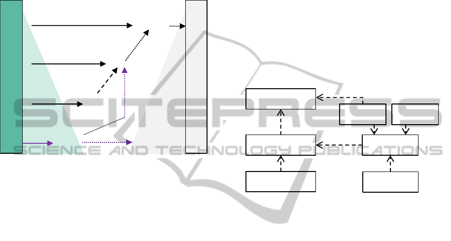
Based on NFRs, the architecture of the system is
designed by using the Model-View-Controller
design pattern (MVC) (Deacon, 2009). This pattern
was described in the first time by Reenskaug
(Reenskaug, 1979). In this design pattern, the model
represents knowledge which can consist of
application data, logic or business rules. In addition,
the model is represented or visualized by the view.
The controller manipulates the model state and
notifies the view which provides the link between
the user and the systems. This pattern can potentially
fulfill the software requirements for the architecture
and GUI of the system. The clear separation of
model data from the elements of GUI allows
implementing the extensible system. Moreover, the
elements of user interface can be modified and
improved apart from the model. Figure 8 displays
DesigningCAx-processChains-ModelandModelingLanguageforCAx-ProcessChainMethodology
731
the architecture for the “CAx-process chain
designer”.
Figure 8: Architecture.
In this case, the model consists from the nodes and
edges which contain information about CAx-PC
(chain data). The model notifies the view through
the controller about any changes in chain data. The
model is initiated by the generated XML
configuration files and program code. The chain data
is stored in the model and external data storages.
User Interface elements display the state of the
model. The controller translates the user actions into
commands which change the state of the model and
view’s perception of the model. The user interface
includes the main elements such as a canvas,
dynamic menus, process control elements and a
property panels to display detailed information about
the processes.
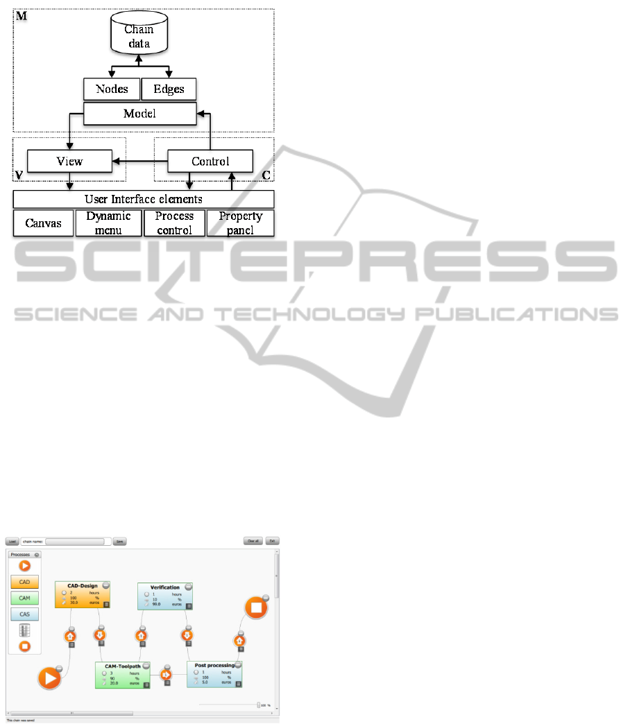
Figure 9: The prototypical GUI for CAx-process chain
designer.
These elements form the GUI of “CAx-process
chain designer”. The first prototype of GUI is
illustrated in Figure 9. This implementation of
“CAx-process chain designer” is prototypical.
Currently, the prototype is capable of visualizing
and manipulating the CAx-PC model. After several
iterative development cycles the research prototype
will analyse and evaluate CAx-PCs for designing the
alternatives of CAx-PC.
5 CONCLUSIONS
This paper introduces a solution for designing CAx-
PC in conformity to the CAx-PC methodology for
evaluation, analysis and optimization of CAx-PC.
The solution includes the definition of DSL,
expressing the model and the tool for deriving the
alternatives of process chains from the model. The
CAx-PC methodology is based on the knowledge
that has been extracted throughout different use
cases within the turbo machinery and automotive
industries. Further use cases from other industry
sectors might lead to extensions of the methodology
as well as the redefinition of the model, metamodel
and modeling language.However, the presented
solution requires a detailed description of DSL
definition. Therefore, the future work will be
concentrated on the DSL definition. Also, the GUI
of the “CAx-process chain designer” will be
iteratively adapted to software requirements.
REFERENCES
Bass, Len and Clements, Paul and Kazman, Rick (ed.),
2003, Software architecture in practice, Addison-
Wesley Professional.
Bézivin, J., 2005, ‘On the unification power of models’,
Software & Systems Modeling, Springer(4(2)), 171–
188.
Brecher, C., Vitr, M. & Wolf, J., 2006, ‘Closed-loop
CAPP/CAM/CNC process chain based on STEPand
STEP-NC inspection tasks’, International Journal of
Computer Integrated Manufacturing 19(6), 570–580.
Bullinger, H. J., et al. (eds.), 2008, Handbuch
Unternehmensorganisation: Strategien, Planung,
Umsetzung, 3rd edn., Springer Berlin, Berlin.
Cook, S. (ed.), 2007, Domain-specific development with
Visual Studio DSL tools, Addison-Wesley, Upper
Saddle River, NJ.
Deacon J., 2009, ‘Model-view-controller (mvc)
architecture’ 2009, from http://www. jdl. co.
uk/briefings/MVC. pdf.
Eeles P., 2005, Capturing architectural requirements,
from http://ibm.com/developerworks/rational/library.
Efftinge S., Völter M., 2006, ‘oAW xText: A framework
for textual DSLs’, Workshop on Modeling Symposium
at Eclipse Summit 32.
ICINCO2014-11thInternationalConferenceonInformaticsinControl,AutomationandRobotics
732

Feldhusen, J. & Grote, K.-H., 2013, ‘Pahl/Beitz
Konstruktionslehre: Methoden und Anwendung
erfolgreicher Produktentwicklung’, Pahl/Beitz
Konstruktionslehre 2013.
Fowler, M., 2008, Domain-specific languages, from
http://martinfowler.com/bliki/DomainSpecificLanguag
e.html.
Fowler, M., 2005, ‘Language workbenches: The killer-app
for domain specific languages’ 2005.
Fowler, M., 2010, Domain-specific languages, Pearson
Education.
Grady, R. B., 1992, Practical software metrics for project
management and process improvement, Prentice Hall,
Englewood Cliffs, NJ.
Hutchinson, J., Rouncefield, M. & Whittle, J., 2011,
‘Model-driven engineering practices in industry’, in R.
N. Taylor, H. Gall, & N. Medvidović (eds.),
Proceeding of the 33rd international conference,
Waikiki, Honolulu, HI, USA, pp. 633–642.
Jackson, M., 1995, ‘Requirements and specifications: a
lexicon of software practice, principles and
prejudices’, Addison Wesley, Wokingham 1995.
Kelly, S., & Tolvanen, J. P., 2000, ‘International
Workshop on Model Engineering: Visual domain-
specific modeling: Benefits and experiences of using
metaCASE tools’, ECOOP 2000.
Klocke, F. & Straube, A.M., 2004, ‘Virtual Process
Engineering – An approach to integrate VR, FEM, and
simulation tools in the manufacturing chain’,
Mécanique & Industries 5(2), 199–205.
Kosar, T., Oliveira, N., Mernik, M., Pereira, V.,
Crepinsek, M., Da, C. & Henriques, R., 2010,
‘Comparing general-purpose and domain-specific
languages: An empirical study’, Computer Science
and Information Systems 7(2), 247–264.
Ludewig, J. & Lichter, H., 2007, Software Engineering:
Grundlagen, Menschen, Prozesse, Techniken, 1st edn.,
Dpunkt-Verl., Heidelberg.
Minoufekr, M.; Glasmacher, L. & Adams, O. (2013),
Macroscopic Simulation of Multi-axis Machining
Processes., in Jean-Louis Ferrier; Oleg Yu. Gusikhin;
Kurosh Madani & Jurek Z. Sasiadek, ed., 'ICINCO (2)'
, SciTePress, , pp. 505-516 .
Nielsen, J., 2005, ‘Ten usability heuristics’ 2005.
OMG, 2005, Unified Modeling Language (UML), from
http://www.omg.org/spec/UML/2.0.
OMG, 2011, Business Process Model and Notation
(BPMN), from http://www.omg.org/spec/BPMN/2.0.
Reenskaug, Trygve Mikjel H, 1979, ‘The original MVC
reports’ 1979.
Sääski J., Salonen T. and Jukka P., 2005, ‘Integration of
CAD, CAM and NC with Step-NC’, VTT 2005.
Schug P., Glasmacher L., Klocke F., 2014, ‘Modeling und
Evaluation of CAx-Process chains’, Innovations of
Sustainable Production for Green Mobility, 3rd
International Chemnitz Manufacturing Colloquium
ICMC 2014(1), 872–891.
Steinberg, D. (ed.), 2009, EMF: Eclipse Modeling
Framework, 2nd edn., Addison-Wesley, Upper Saddle
River, NJ.
Taylor, R. N., Gall, H. & Medvidović, N. (eds.), 2011,
Proceeding of the 33rd international conference.
Tolvanen, J.-P. & Rossi, M., 2003, ‘MetaEdit+: defining
and using domain-specific modeling languages and
code generators’, Companion of the 18th annual ACM
SIGPLAN conference on Object-oriented
programming, systems, languages, and applications
2003, 92.
Werner Dankwort, C., Weidlich, R., Guenther, B. &
Blaurock, J. E., 2004, ‘Engineers' CAx education—it's
not only CAD’, Computer-Aided Design 36(14),
1439–1450.
Wiegers, K. E., 2000, ‘Karl Wiegers describes 10
requirements traps to avoid’, Software Testing &
Quality Engineering 2(1).
DesigningCAx-processChains-ModelandModelingLanguageforCAx-ProcessChainMethodology
733
