
WLAN Interface for a Wireless EEG System
E. Velarde-Reyes and F. Martin-Gonzalez
Cuban Neuroscience Center, Havana, Cuba
Keywords: WLAN, Interface, Wireless, EEG, Holter.
Abstract: A WLAN interface for a Wireless EEG System is presented in this paper. Selection of broadcasting band,
available hardware, and connection algorithm to use are discussed before making a choice. Two alternatives
were explored: Wireless EEG Device (Holter) and its Server communicate with each other within the same
physical network, and from a complex network like the Internet. Results of experimental tests carried out on
the prototype demonstrate the functionality of the implemented interface.
1 INTRODUCTION
Electroencephalography (EEG) studies are
increasingly important in numerous applications,
from clinical diagnosis of different brain pathologies
to research on cognitive processes and to the
development of brain-computer interfaces and
neurofeedback. In some of these applications long-
lasting recordings are required and desk
electroencephalographs with personal computer
(PC) wired interfaces as USB, are not the best
solution since they restrict patient movements. Such
is the case of study and diagnosis of epilepsy whose
studies can last up to three continuous days. This
has brought attention to the need of developing
wireless interfaces in order to add telemetry
capability to EEG recorders.
Other requirement for EEG long-lasting recordings
is the portability of the recorder. Portable devices
with telemetry capability and possibility to record
medical data in an ambulatory way may receive the
generic name of Holter monitors. Holter monitor,
the PC where the doctors process EEG studies
(Server) and the possible communications
infrastructure conform a Wireless EEG System
(WES).
Moreover, WLAN is the protocol commonly used in
PC-based wireless networks. Some hospitals use
this telecommunication technology in automation of
processes. Doctors can immediately access medical
records and patients’ special medication by means of
this technology (Goldman, 2008). If our WES
supports WLAN, we can guarantee monitoring of
patients at all times and in all places in the hospital,
by adapting into existing WLANs or installing new
ones. This makes WLAN a very convenient option.
The aim of this paper is to describe the design and
implementation of a WLAN interface for a Wireless
EEG System.
2 DESIGNING THE WLAN
INTERFACE
2.1 Broadcasting Band
In order to ensure its compatibility with installed
systems, broadcasting band of our WES must be
recognized as a license-free band in the majority of
countries around the world. Therefore, we selected
the frequency band between 2400–2483.5 MHz.
This band is frequently used by numerous devices
such as microwave ovens, wireless phones, RFID
units, and wireless local area networks (WLANs),
causing a potential source of strong interference
between devices within a domestic or hospital
environment. There exist various techniques for
decreasing the interference impact. The advantages
of the selected broadcasting band include the short
length of antennas, the existence of relatively cheap
radio frequency transceivers and certified modules
that work in the band, the universal acceptance of
the band, and the better propagation characteristics
over other world-wide accepted bands such as 5727–
5875 MHz.
89
Velarde-Reyes E. and Martin-Gonzalez F..
WLAN Interface for a Wireless EEG System.
DOI: 10.5220/0005067900890093
In Proceedings of the 2nd International Congress on Neurotechnology, Electronics and Informatics (NEUROTECHNIX-2014), pages 89-93
ISBN: 978-989-758-056-7
Copyright
c
2014 SCITEPRESS (Science and Technology Publications, Lda.)

2.2 Bit Rate Demands of the WES
In EEG recording is recommended a sampling rate
of at least 200 Hz and a resolution of 12 bits. Even
so, higher sampling rates and resolutions are
preferable.
An EEG Holter monitor which could record data of
40 channels in simultaneous mode using a sampling
rate of 400 Hz and coding the samples with 24 bits
needs a data throughput of 384 kbps. That data
throughput is achievable in any WLAN network as
discussed later on.
2.3 WLAN Standard
One of the fundamental advantages of WLAN over
other standards is the ability to connect to a local
area network (LAN) using a wireless Access Point
(AP), which allows patient monitoring in a most
extense area and the development of future
applications of telemedicine.
WLAN or IEEE 802.11 is a family of specifications.
Among them, IEEE 802.11b and IEEE 802.11g are
the most ubiquitous, and is very convenient that our
WLAN interface supports them both. Both
specifications of the WLAN work in the 2400–
2483.5 MHz band and implement modulation
techniques against interferences, as DSSS, FHSS
and OFDM (Proakis, 2008). Also, WLAN allows
retransmission in case of occurring errors in
transmission or reception and supports throughputs
from 1 to 54 Mbps in the case of IEEE 802.11b and
IEEE 802.11g specifications.
2.4 WLAN Interface Implementation
Our WLAN Interface must be integrated, in its more
simplified form by: one antenna for the transmission
and reception of RF signals, one RF transceiver and
one base band modulator with an 802.11 MAC
Layer implementation.
In the short term, among the options to develop a
WLAN Interface using integrated circuits and to
acquire a certified WLAN integrated module, the
most economic one is the second. There exist
WLAN integrated modules having a
firmware/hardware implementation of a TCP/IP
(transmission control protocol/internet protocol)
stack, that results essential for an adequate
communication into a LAN network.
In summary it is very important that the selected
WLAN integrated module has the following
characteristics: low power consumption (Holter
monitor necessarily works with battery) and a proper
implementation of a TCP/IP stack.
3 WES MERGED IN THE
COMMUNICATIONS
INFRASTRUCTURE
Our Wireless EEG System could face two situations
using WLAN standard:
1. The Server is in the same physical network.
2. The Server is in an infrastructure network.
Our WES must be authenticated and associated in a
WLAN for transmitting data, it is an unavoidable
requirement. The WLAN can be an infrastructure or
ad hoc network. In the first case, authentication and
association processes are executed by Holter
monitor and an AP, while in the second case the
processes are executed by Holter monitor and a
WLAN module embedded in a PC. Authentication
and association are indispensable conditions for a
successful data interchange, but it is also necessary
to know the destination and source internet protocol
(IP) addresses and to possess a suitable TCP/IP
stack. Moreover, source and destination devices
must implement a network layer protocol for IP
address dynamic assignation (e.g., Dynamic Host
Configuration Protocol, DHCP). Since WLAN is a
network-oriented standard, it would be convenient
for our WES to include some protocols of the
transport layer (e.g., TCP and UDP). There are
some IEEE 802.11 embedded modules that, besides
physically implementing the communication,
incorporate a complete stack of TCP/IP protocols.
In accordance with the type of situation, our
Wireless EEG System must employ a different
technique or algorithm in order to connect to its
server.
3.1 The Server Is in the Same Physical
Network
In the case that Server is in the same physical
network of the Holter monitor (Client from now on),
it is appropriate that they implement a connection
algorithm that resolves the Server’s IP address and
enables medical data transmission through a
transport layer protocol. This algorithm must ensure
connectivity and good performance in any network
topology. It is convenient that it be simple, with low
program processing times, and therefore easy for
programmable devices to implement.
NEUROTECHNIX2014-InternationalCongressonNeurotechnology,ElectronicsandInformatics
90

We propose a new version of algorithm presented in
Velarde-Reyes et al (2008). This algorithm (Figure
1) ensures a fast and reliable data interchange and
has four stages: annunciation, acceptation, TCP
connection establishment and reconnection. In the
annunciation stage, the Client must begin the
communication as soon as it has been authenticated
and associated in a WLAN. Communication is
initiated by the transmission of a command sequence
that travels within UDP datagrams addressed to the
broadcast address and to a specific registered port.
Commands consist in annunciation’s indicatives that
will reach all hosts inside the same physical
network. Inside annunciation’s indicatives are the
Client IP address and the registered port opened by
the Client. Annunciation’s indicatives are
repetitively transmitted until the Client receives the
Server’s acceptation commands. The application
running on the Server opens its specific registered
port and receives the annunciation’s indicatives. As
soon as the Server obtains that information, it
permits data transmission to the Client. This new
stage is known as acceptation, and it is executed by
the Server in automatic or manual (by the Server’s
user) form. The Server can simultaneously allow
various Clients to pass to the next stage:
Acceptation.
Acceptation is accomplished by sending commands
to the Client IP address. These commands travel in
UDP datagrams and consist in acceptation’s
indicatives that contain the Server IP address and the
TCP port opened for the next connection.
After the acceptation stage is TCP connection
establishment. In this stage, the Server opens the
TCP registered port indicated in the acceptation
command. Then it starts a passive opening and
waits for a TCP connection establishment. After the
TCP connection establishment stage, the Server send
to Client a TCP Connection Established Indicator
(“Go”) every 3 seconds announcing that it is
prepared to receive all the data sent by the Client.
Client must response to that indicator with a “Go”
ack in case that it is not transmitting medical data.
If Client could not receive “Go” Indicators, it will
initiate the reconnection stage, establishing again a
TCP Connection with previous Server. Also, if
Server could not receive data or “Go” acks, it will
initiate too the reconnection stage, waiting for a TCP
connection establishment by its open TCP port.
3.2 The Server Is in an Infrastructure
Network
In this section we named Infrastructure Network to
the networks that connect different network devices
which are located in different physical networks. In
this case, data travels through different network
nodes (switches, routers, bridges, or others). A
group of interconnected LANs and WANs (wide
area networks) that conforms to the Internet
infrastructure are examples of an Infrastructure
Network.
Our Client could not connect to its Server in this
kind of network using the algorithm proposed in the
previous section. The difficulty is that the broadcast
UDP messages cannot travel out of its physical
networks because most routers in their default state
do not have that configuration. Therefore, it is
indispensable to use a new connection mode in order
to establish a TCP connection between our Client
and its Server when they are in different physical
networks.
The new proposed connection mode is by means of
the use of the Domain Name System (DNS) protocol
services. DNS is a mechanism that implements a
machine name hierarchy for computers, services, or
any resource connected to any network. It associates
several information with domain names assigned to
each of the resources in the network. Its most
important function is to translate domain names
meaningfully to humans into the numerical
addresses associated with networking equipment (or
any resource) for the purpose of locating and
addressing these devices worldwide.
DNS uses a hierarchical naming scheme known as
domain names. A domain name consists of a
sequence of subnames separated by a delimiter
character, the period. Thus, the domain name
electron.cneuro.edu contains three subnames:
electron, cneuro, and edu. Any subname in a domain
name is also called a domain. In the above example
the lowest level domain is electron.cneuro.edu, (the
domain name for the Electronic Design Department
at the Cuban Neuroscience Center), the second level
domain is cneuro.edu (the domain name for the
Cuban Neuroscience Center), and the top level
domain is edu (the domain name for educational
institutions). DNS protocol makes it possible to
assign domain names to users or groups (e.g.,
Internet users) in a meaningful way, independent of
each user’s physical location. Because of this,
Internet contact information can remain consistent
and constant even if the current Internet routing
arrangements change.
Using the DNS protocol, our Client can establish a
TCP connection with its Server if the Server has a
domain name (e.g., epilepticserver.electron.edu.cu).
It will not matter if the Server IP address is unknown
WLANInterfaceforaWirelessEEGSystem
91
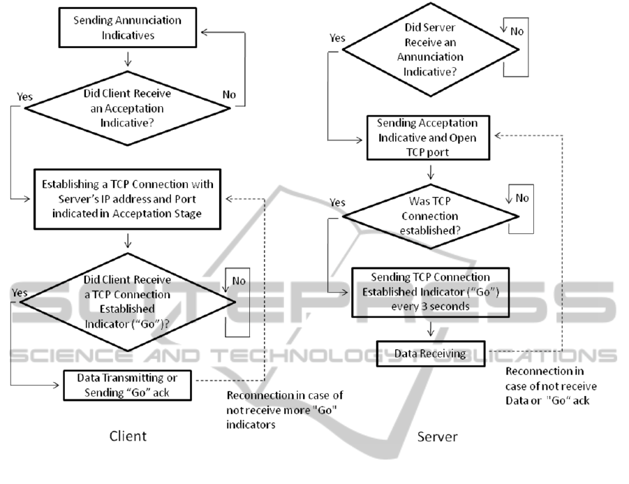
Figure 1: Connection Algorithm.
to it. To use the DNS protocol our Client must
implement a complete stack of TCP/IP protocols.
4 INTERFACE VALIDATION
For validating the wireless communication interface
we built a prototype integrated by an OWS451
module from ConnectBlue and a microcontroller.
The broadcasting power selected for the module was
+17 dBm. The microcontroller was used for
executing the tasks assigned to the Client in the
connection algorithm. A PC was used as Server.
Two experiments were selected for modelling the
two principal scenarios that could face a WES in its
same physical network. They were:
Experiment 1 consisted of broadcasting data
inside a room from a fixed position using
multipath trajectories. This situation modelled
a hospital room scenario due to the geometry of
the room and the materials of the walls and
furniture (Schäfer et al, 2005).
Experiment 2 consisted of broadcasting data
inside a corridor using line of sight (LOS)
trajectories. The corridor selected is similar to
other modern hospital corridors, with similar
dimensions and materials (Schäfer et al, 2005).
In both experiments the Packet Error Rate (PER)
was measured and the faults in the connection
algorithm were counted. In Velarde-Reyes et al
(2008) are depicted in detail the two experiments.
4.1 Considerations about the
Experimental Results
The experimental results show that the proposed
connection algorithm guarantees the WES
communication and it works satisfactorily in multi-
path and LOS trajectories.
5 CONCLUSIONS
The main result of this work was the description of
the design and implementation of a WLAN interface
for a Wireless EEG System.
NEUROTECHNIX2014-InternationalCongressonNeurotechnology,ElectronicsandInformatics
92

REFERENCES
Goldman, J., 2008. Wireless Hospital: Orlando Regional
Healthcare. In Wi-Fi Planet, March 13, 2008, accessed
30 April 2014, <http://www.wi-fiplanet.com/columns/
article.php/3734011> .
Proakis, J., 2008. Digital Communications, Mc Graw -
Hill. New York, 5
nd
edition.
Velarde-Reyes, E., Marante-Rizo, F., Morgalo-Santos, B,
Garrote-Jorge, J., and Martin-Gonzalez, F., 2010.
Wireless communication interface for EEG/PSG
Holter monitor. In Journal of Medical Engineering &
Technology, vol. 34, pp. 172-177, April 2010.
Schäfer, T., Maurer, J., Hagen, J., and Wiesbeck, W..
2005. Experimental Characterization of Radio Wave
Propagation in Hospitals. In IEEE Transactions on
Electromagnetic Compatibility, vol. 47, pp. 304-311,
May 2005.
WLANInterfaceforaWirelessEEGSystem
93
