
BLINDTRACK: Guiding System for Visually Impaired
Locating System for Running on a Track
Ferdinand Kemeth
1
, Sven Hafenecker
1
,
´
Agnes Jakab
2
,
M
´
at
´
e Varga
2
, Tam
´
as Csielka
2
and Sylvie Couronn
´
e
1
1
Fraunhofer Institute for Integrated Circuits, Nuremberg, Germany
2
Ateknea Solutions, Budapest, Hungary
Keywords:
Real-time Locating System, Angle of Arrival, Round-trip Time, Visually Impaired Runners, Guiding System.
Abstract:
Visually impaired people need to renounce several social activities what the sighted people can enjoy. In this
paper we refer to the project BLINDTRACK which has the major goal to develop a guidance system. A
real-time locating system (RTLS) based on radio signals guides the runners with the highest level of safety
by estimating the angle of arrival (AoA) and round-trip time (RTT). First results show the position accuracy
of the proposed locating system with real-world data. BLINDTRACK provides an enormous freedom for
the visually impaired runners in compare to the other solutions: Sighted and blind runners will have the
opportunity to perform sport together without another person’s assistance.
1 INTRODUCTION
In recent years the EU and all its member countries
have committed themselves to create a barrier-free
Europe. There are still many obstacles preventing
people with disabilities from fully exercising their
fundamental rights including their Union citizenship
rights and restricting their participation in society on
an equal basis compared with non-disabled people.
Those rights include the right to free movement, to
choose where and how to live, and to have full access
to cultural, recreational, and sports activities. Regard-
ing sports, particular running activities, visually im-
paired do not have equal possibilities.
The most common way of running is the so-called
guided running in that blind runners train and race
with a sighted runner with the help of a tether (Amer-
ican Foundation for the Blind, 2014). With the
BLINDTRACK project the Consortium aims to raise
the level of accessibility of visually impaired to sport
to reflect the need for an effective assistive technol-
ogy which would facilitate the well-being of visually
impaired while decreasing their exclusion from sport
and leisure activities. The proposed system helps vi-
sually impaired people integrate to the community
with increasing confidence, better health condition
and higher tolerance level of sighted people.
The aim of BLINDTRACK project is to develop
a running facility embedded to a 400 m athletic track
for visually impaired people to run without another
person’s assistance. BLINDTRACK will be able to
bring significant changes in training opportunities for
visually impaired. The objective is to increase the
number of blind and partially sighted athletes with
the creation of a tailored infrastructural facility that
can be the first step to train without sighted volun-
teers. Although BLINDTRACK focuses on visually
impaired users, the system provides online available
training results to the sighted people: This enhances
the market opportunities and further development for
small and medium enterprises (SME).
In this paper we focus on the project’s locating
part as follows: Section 2 provides an overview for
the proposed system and the project organization.
Section 3 gives basics on the used locating techniques
and Section 4 shows the locating performance of the
system under development. The last section summa-
rizes the paper together with the next steps.
(European Commission, 2010) (United Nations,
2007) (England Athletics Limited, 2012) (United
States Association of Blind Athletes, 2014) (Com-
petitor.com, 2014)
183
Kemeth F., Hafenecker S., Jakab Á., Varga M., Csielka T. and Couronné S..
BLINDTRACK: Guiding System for Visually Impaired - Locating System for Running on a Track.
DOI: 10.5220/0005143001830189
In Proceedings of the 2nd International Congress on Sports Sciences Research and Technology Support (icSPORTS-2014), pages 183-189
ISBN: 978-989-758-057-4
Copyright
c
2014 SCITEPRESS (Science and Technology Publications, Lda.)

2 BLINDTRACK OVERVIEW
The BLINDTRACK system structure is intended to
built up three main components:
• the BlackFIR (Fraunhofer IIS, 2012) unit which is
a high precision locating system,
• the belt unit which is a vibro tactile belt and
• a Central Control Unit (CCU).
2.1 System Description
The BlackFIR has the responsibility to locate the ath-
letes on the track in real time, while the belt unit co-
ordinates the athletes with vibrations while running
and helps them to avoid the obstacles and the colli-
sion situations. The CCU predicts and calculates the
different trajectories for each athlete and also filters
and singles out the right commands to be sent.
Figure 1 shows the general architecture of the
complete BLINDTRACK system. It is necessary to
create an own local BLINDTRACK network on the
athletic field, which is completely separated from the
local area network. This separation ensures to keep
the BLINDTRACK server safe, prevents the unde-
sired system overloads and shutdowns and makes the
operation fast and continuous. The server has a Linux
operating system and a runtime environment to fulfil
the controlling tasks that includes the calculation of
the trajectories, the selection and transfer of the com-
mands. The CCU has also a client side, where one or
more computers can connect to the BLINDTRACK
server as client device. The client computer has a
graphical user interface (GUI), which helps the oper-
ator who is the supervisor of the athletic field and the
runners. The GUI is also responsible for the adminis-
trative issues and the statistical data display. All these
tasks are not required real time conditions therefore
they are detached from the BLINDTRACK server.
The communication protocol between the mod-
ules is based on novel wireless technologies where
the high speed and reliability are crucial parameters.
The communication with the belt unit will be imple-
mented by Wi-Fi access points that provide easy and
fast information transmission, and prevents the inter-
ference with the BlackFIR locating system. The belt
consists of a driver module and an actuator part. The
driver module is responsible for the communication
towards the CCU and for the control of the belt ac-
tuators. This module also contains a power supply
unit, which drives the complete belt and a compass
module which determinates the relative orientation of
each actuator to the north. The firmware of the belt
has the responsibility for the translation of the rela-
tive to north commands to the actuator. This can min-
imize the intensity of wireless communication in the
BLINDTRACK system.
BlackFIR is an innovative radio frequency (RF)
based locating system, which is able to operate in
real time and detects the exact position of each run-
ner on the track. The BlackFIR system consists of
several antenna units, mobile transponders carried by
athletes and a central unit. The communication be-
tween the antenna units and the central unit occurs via
Ethernet. The mobile transponder comprises a special
transceiver chip to locate and identify the athletes.
Figure 1: General system architecture of the BLIND-
TRACK.
2.2 Project Organization
BLINDTRACK project management structure was
designed and agreed by the consortium members to
ensure an effective and straightforward project man-
agement mechanism. The main principles were to
set up and maintain an organisational structure that
ensures the highest level technical and financial im-
plementation of the project and the efficient exploita-
tion of the project results and effective decision mak-
ing structure. The partners represent several Euro-
pean countries such as Germany (PPS and Fraun-
hofer IIS), Hungary (Ateknea Solutions, BSK, IN-
FOALAP), the Netherlands (Elitac), Norway (Adap-
tor), Spain (Eneso, IBV) and their professional expe-
riences cover all the neccessary fields that are needed
to conclude in a successful project result by the end
of 2015. A more detailed partner description is found
in the Appendix.
3 ADAPTED LOCATING SYSTEM
The BlackFIR system developed at Fraunhofer IIS
consists of four mounted receiver units, upto 30 mo-
bile units (transponders) and a central computing unit.
icSPORTS2014-InternationalCongressonSportSciencesResearchandTechnologySupport
184
The communication between the receiver units and
the central unit occurs via Ethernet. For identifica-
tion and locating the nanoLOC transceiver chip (Nan-
otron Technologies GmbH, 2007) is used. The in-
frastructure measures the angle of arrival (AoA) and
the round-trip time (RTT) using RF signals generated
by the mobile units in the 2.4 GHz ISM frequency
band. Using these two locating techniques every re-
ceiver unit estimates the direction and distance of ac-
tive transponders and sends the results to a central
unit, where the position is determined by combining
all available locating information.
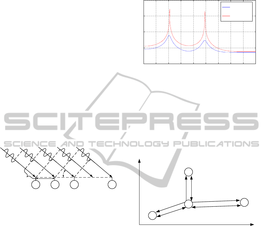
3.1 Basics of AoA
Adaptive antenna arrays allow estimating the angle of
arrival of a received signal (Tuncer et al., 2009). The
received signal source has to be in a far field condi-
tion. Far field condition results in signal propagation,
which is nearly flat. Figure 2 shows the phase alter-
ation on different channels of an antenna array.
...
d
ϴ
ant.1
Δ ψ
ant.2 ant.3 ant.n
Figure 2: Received far field signal at the antenna array.
To estimate the angle of arrival, different high res-
olution algorithms like Multiple Signal Classification
(MUSIC), estimation of signal parameters via rota-
tional invariance techniques (ESPRIT) or the Min-
imum Variance Cappon-Beamformer (Tuncer et al.,
2009) can be applied. These algorithms use the co-
variance of the different received signals to estimate
the angle of arrival. BlackFIR uses a MUSIC al-
gorithm with an additional forward backward spatial
smoothing (FBSS) which improves robustness against
multipath non-line-of-sight (NLOS) signals. The re-
sult of the MUSIC algorithm is an angle spectra like
shown in Figure 3; the maxima of the spectra show the
estimated angle of arrival. The resulting peaks of the
MUSIC spectra get narrower with an additional pre-
processed FBSS. Inherent with this, an improvement
of multipath-robustness against NLOS-signals is also
realized.
3.2 Basics of RTT
The measurement of distances between a tag (”X”)
and given receiver positions (”1”, ”2” and ”3”) allows
0 20 40 60 80 100 120 140 160 180
10
−2
10
0
10
2
10
4
10
6
Angle of Arrival [degree]
P MUSIC
P MUSIC
P MUSIC fbss
Figure 3: MUSIC (power) with and without forward back-
ward spatial smoothing.
the calculation of the tag position, as shown in Fig-
ure 4. BlackFIR uses the nanoLOC transceiver chip
to implement round-trip time (RTT) (Std 802.15.4a,
2007) based distances. The distance is measured by
a so called two way ranging procedure. In this pro-
cedure time of flight (TOF) is measured by anchor to
tag response time and vice versa. This gives the op-
portunity to compensate differences in the frequency
reference of the tag and the anchor.
t1
t3
t2
X
1
2
3
x
y
2x t2
2x t1
2x t3
Figure 4: RTT-based calculation of position.
Another well-known method to measure distances
is to calculate time of arrival (TOA) or time differ-
ence of arrival (TDOA). For TOA it is necessary to
have synchronisation between receiver and transmit-
ter which is often not possible in an adequate way.
Due to that TDOA is a possibility, where only the in-
frastructure is synchronized such as in satellite based
global positioning systems (GPS). Using TDOA does
not require an extra reply signal which lowers the
channel usage and minimizes the measurement time.
However RTT requires no synchronisation techniques
between the receiver units, what influences the system
infrastructures as well as increasing the cost.
3.3 Infrastructure Setup
The BlackFIR locating system consists of a receiver
unit estimating the AoA and the RTT. In order to cal-
BLINDTRACK:GuidingSystemforVisuallyImpaired-LocatingSystemforRunningonaTrack
185
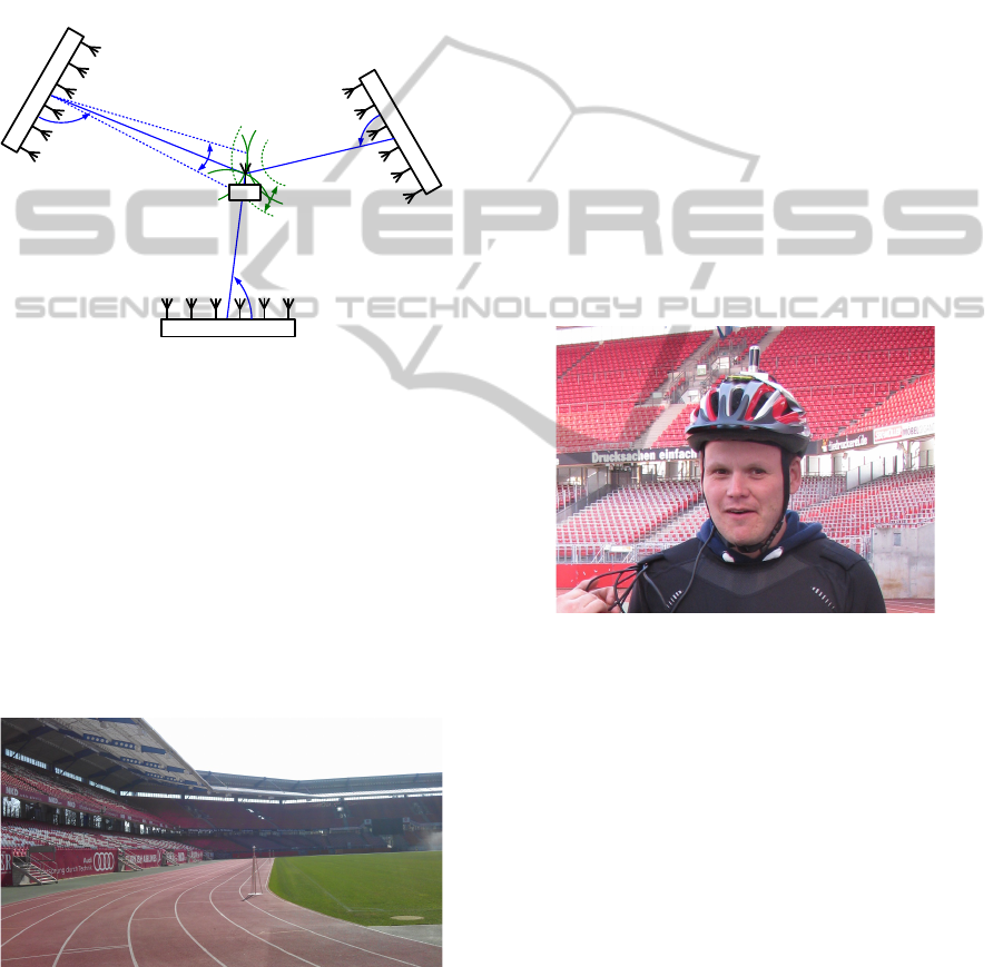
culate a two-dimensional position, it is necessary to
use at least one of these receiver units. In practice
the data is affected by multipath effects, fading and
noise based error. To improve the estimates, more
units are used at one scenario in a time duplex sequen-
tial measurement procedure as shown in Figure 5. All
available sensor data are collected and combined by a
central server were the position is then calculated by
either a Kalman filter (Kalman, 1960) or particle filter
(Sanjeev et al., 2002) based algorithms.
angle 3
AOA / RTT Receiver 1
AOA
/
RTT
Receiver 2
AOA
/
RTT
Receiver 3
TAG
2 ε_angle
2 ε_distance
distance 2
Figure 5: Principal abstract of BlackFIR RF locating.
4 EVALUATION
4.1 Measurement Campaign
In order to validate the performance values, a mea-
surement campaign was executed in the N
¨
urnberg sta-
dium. The used test field is a standardised (DIN
18035-1, 2003) type ”A” all-weather running track
with eight lanes and a length of 400 m as shown in
Figure 6.
Figure 6: All-weather running track used for testing.
Aim of the measurement campaign:
• Identify the performance of the system in the tar-
get environment.
• Evaluate the optimal infrastructure structure.
• Optimize the positioning algorithms.
To analyse the current system performance in dif-
ferent circumstances, the following scenarios were
explored:
• Walking Scenario. A person was walking along
the third running track. The sender was affixed
at his inner shoulder. The scenario was repeated
three times.
• Running Scenario. A person was running along
the third running track. Likewise the walking sce-
nario, the sender was fixed at his inner shoulder.
• Scenario with a Bicycle Rider. A person was
riding a bicycle along the third running track. The
sender was carried in the outer hand.
To get reference information for the positions an
optical highly accurate system called iGPS (Nikon
Metrology, 2010) was used. The optical component
was mounted on a helmet worn by the athlete as
shown in Figure 7. IGPS ensures point locating ac-
curacy down to 200 µm.
Figure 7: iGPS probe mounting at the top of a helmet.
During the different scenarios various datasets of
sensor information were recorded to analyse and im-
prove the locating system.
The types of raw information are:
• In-phase and quadrature components of the RF
signal received by the antenna unit
• Measured distances between mobile tag and re-
ceiver
• Estimated angle of arrival at the receiver units
• Battery life-time information
Four receiver units were placed arround the run-
ning track (one unit for every 45-degree bend) in or-
der to ensure line-of-sight to the transponders and for
coveraging the whole test field.
icSPORTS2014-InternationalCongressonSportSciencesResearchandTechnologySupport
186
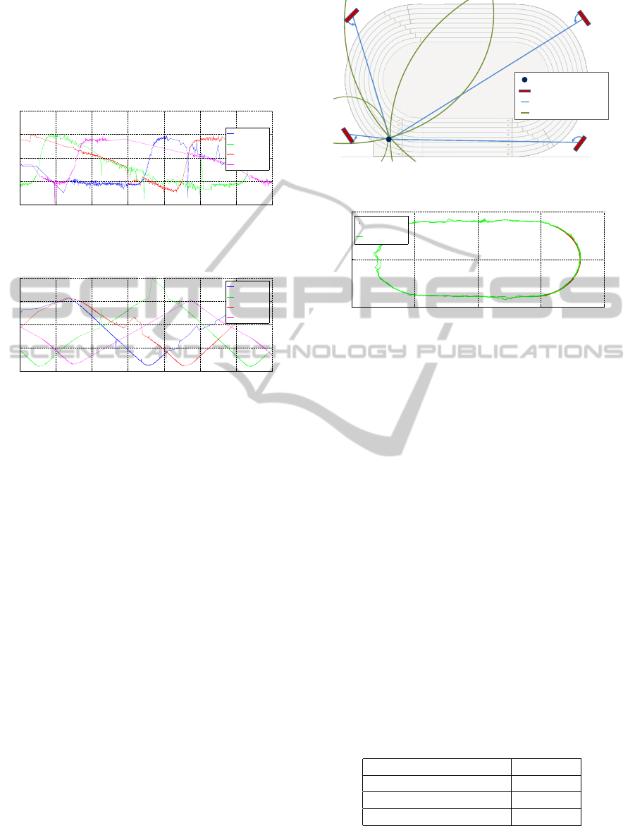
4.2 Analysis
In Figure 8 and Figure 9 the measured raw angle of
arrival and raw distance data over the time are shown.
Each signal of the different receivers is plotted in an-
other colour.
5.442 5.444 5.446 5.448 5.45 5.452 5.454 5.456
x 10
4
0
50
100
150
200
Time [sec]
Angle [degrees]
Receiver 1
Receiver 2
Receiver 3
Receiver 4
Figure 8: Angle results based on Angle of Arrival estima-
tion.
5.442 5.444 5.446 5.448 5.45 5.452 5.454 5.456
x 10
4
0
50
100
150
200
Time [sec]
Distance [m]
Receiver 1
Receiver 2
Receiver 3
Receiver 4
Figure 9: Distance results based on round-trip time.
Every single curve shows spikes depending on
channel propagation, fading and multipath effects
(e.g. Receiver 1 in Figure 8 at 5.451 · 10
4
sec). Be-
cause of the dynamic scenario caused by the runner’s
movement, these effects can be detected and compen-
sated later.
Straight lines are representing gabs in the infor-
mation caused by a poor wireless connection or inter-
ferers (e.g. Receiver 4 in Figure 8 in the time interval
between 5.448 and 5.451 · 10
4
sec). Due to the sys-
tem’s high update rate and redundancy, it is not nec-
essary to get information from every receiver unit at
all times.
An exemplary view of the actual measured dis-
tances and estimated angles is presented in Figure 10:
Each of the four receiver units is showing the esti-
mated angle as a straight line towards the sensors’ po-
sition. The circles around them are representing the
measured distances. In best cases, all lines and circles
are crossing in one single point: the athlete’s position.
The iGPS reference system was installed in the
right part of the stadium due to the need of reference
values. The estimated system latency as well as the
accuracy of the position is determined by the data ob-
served in that part of the stadium. In contrast to that,
the data rate was determined over all data stored in the
corresponding scenario.
Figure 11 shows the position trajectory of the
Runner‘s Position
Receiver Unit
Estimated Angle
Estimated Distance
Figure 10: Position measurement with angle and distance
estimation.
−100 −50 0 50 100
−50
0
50
x−Axis [m]
y−Axis [m]
Reference
Calculated
Figure 11: Measured position in the scenario with a running
person.
measured position values (green line) in the scenario
with a running person for two laps. The red line repre-
sents the position given by the iGPS reference system
which could only cover the right part of the running
track. The position estimates have a small variance
from the reference position. In addition, the estimates
at the right part of the stadium have better perfor-
mance compared with position estimates from the left
part. Reason: The calibration process was performed
in the right part, where the iGPS system was installed,
so the left antennas were not calibrated as fine as the
right antennas. The measurement results of the two
laps are both similiar to each other and comparable to
the described effects.
The estimated accuracy of the position is deter-
mined by the data that where observed in that part
of the stadium, where the iGPS reference system was
installed due to the need of reference values. In con-
trast to that, the data rate was determined over all data
stored in the scenario. Table 1 summarizes the mea-
sured system performance:
Table 1: Summary of measurement results.
Estimated latency 440 msec
Data rate 6.6 Hz
Mean deviation (MAE) 0.689 m
Maximum deviation 2.60 m
”Estimated latency” describes the delay between
the athlete’s actual and calculated position caused by
wireless transmission, network traffic and proccess-
BLINDTRACK:GuidingSystemforVisuallyImpaired-LocatingSystemforRunningonaTrack
187

ing time for the algorithms. ”Data rate” describes the
update rate of the estimated positions; the update rate
for the beld commands sent to the athlete will be less.
The distribution of the measured position errors is
shown in Figure 12.
Figure 12: Distribution of the position error in meters.
5 SUMMARY & ROADMAP
In the scope of this paper, we presented an adaptation
for the BlackFIR locating system to the project needs
of BLINDTRACK. For a system using RTT and AoA
technology, we showed detailed results on a measure-
ment campaign and the accuracy of the calculated po-
sitions. Our system gives visually impaired people
the opportunity to enjoy several social activities with
simple installation complexity. Compared to visual
tracking system, we are able to identify and track ev-
ery runner, even in extreme situations, where the run-
ner is surrounded by many others. In next steps, ad-
justments will be applied resulting in increasing the
accuracy of the current system and further cost reduc-
tion. At the end of this project, the complete system
will be tested and evaluated with blind and non-blind
runners.
ACKNOWLEDGEMENTS
The project has received funding from the European
Union Seventh Framework Programme (FP7/2007-
2013) under the grant agreement No. 605821. It is
a 24 months research project that was launched on 1st
of January 2014 with the cooperation of nine partners.
We thank Mohammad Alawieh, Fraunhofer IIS,
for supporting and revising the paper.
REFERENCES
American Foundation for the Blind (2014). Tips for
runners with visual impairments. http://www.afb.org/
info/living-with-vision-loss/recreation/running-2805/
235.
Competitor.com (2014). Visually impaired runners ready
to tackle boston. http://running.competitor.com/2014/
04/news/visually-impaired-runners-ready-tackle-
boston 98512.
DIN 18035-1 (2003). Sports grounds - part 1: Outdoor play
and athletics areas, planning and dimensions.
England Athletics Limited (2012). Running & sprint-
ing with guides. http://metroblindsport.org/
downloadlibrary/guide-running-v2.pdf.
European Commission (2010). European disability strat-
egy 2010-2020: A renewed commitment to a barrier-
free europe. http://eur-lex.europa.eu/LexUriServ/
LexUriServ.do?uri=COM:2010:0636:FIN:EN:PDF.
Fraunhofer IIS (2012). BLACKFIR 2.4 brochure.
Kalman, R. (1960). A New Approach to Linear Filtering
and Prediction Problems. Journal of Basic Engineer-
ing, 82 (series d) edition.
Nanotron Technologies GmbH (2007). nanoNET Chirp
Based Wireless Networks White Paper.
Nikon Metrology (2010). iGPS datasheet: Priciples of op-
eration / Scalebar / i5 Probe kit / Dynamic tracking
kit.
Sanjeev, Arulampalam, M., Maskell, S., Neil, G., and
Clapp, T. (2002). A Tutorial on Particle Filters for
Online Nonlinear/Non-Gaussian Bayesian Tracking.
IEEE Transactions on Signal Processing, vol.50 edi-
tion.
Std 802.15.4a (2007). IEEE Standard for Information Tech-
nology - Telecommunications and Information Ex-
change Between Systems - LANs and MANs - Specific
Requirements - Part 15.4: Wireless MAC and PHY
Specifications for LR-WPANs - Amendment 1: Add Al-
ternate PHYs. IEEE Std 802.15.4aTM-2007 edition.
Tuncer, T., Friedlander, B., and Yasar, T. (2009). Classical
and Modern Direction-of-Arrival Estimation. Aca-
demic Press.
United Nations (2007). Convention on the rights of per-
sons with disabilities. http://www.un.org/disabilities/
default.asp?navid=13&pid=150.
United States Association of Blind Athletes (2014).
Sports adaptations. http://usaba.org/index.php/sports/
sports-adaptations/.
APPENDIX
SME Participants
INFOALAP-Informatics for the Visually
Impaired Foundation - Hungary
INFOALAP is actively involved in system specifica-
tions, based on its experience with IT for visually im-
paired, and supports the technology optimization by
providing direct evaluation feedback for. They also
support hardware and software development by the
evaluation of ergonomic aspects by its low vision IT
engineers, as well as being active in system tests.
icSPORTS2014-InternationalCongressonSportSciencesResearchandTechnologySupport
188

PPS GmbH - Germany
PPS is the supplier of the technology that is capable of
real-time detection of the running people in the run-
ning track. It closely cooperates with Fraunhofer In-
stitute IIS during the research period and supplies the
prototype of the project. PPS defines the prototype in
regard of later products and assists the development
partners in defining the real use cases as well as the
general evaluation of the developments.
ELITAC - Netherlands
Besides supervising, ELITAC’s role comes at the
phase of tactile belt research and manufacturing.
They strongly cooperate with IBV while they are
working on the development of the tactile belt. ELI-
TAC has already developed tactile devices but none of
them was for the blind.
Eneso Tecnolog
´
ıa de Adaptaci
´
on S.L. - Spain
ENESO is a distributor of BLINDTRACK system.
They have a deep knowledge of the accessibility mar-
ket in Spain, so they will be very active in promoting
and placing the system. They will also contribute their
experience by testing and validating the product.
ADAPTOR HJELPEMIDLER AS - Norway
ADAPTOR plays a significant role in the consortium
as the employer of visually impaired and distributor of
assistive products and provides the research partners
with tangible information on the needs of the market
and assist field testing.
RTD Participants
ATEKNEA Solutions Hungary Kft. - Hungary
Ateknea Solutions brings together four research and
innovation companies operating at a European level
for over 15 years. The group pools the expertise and
know-how of more than 130 professionals working
in five different locations: Barcelona, Brussels, Bu-
dapest, Krakow and Valetta. The innovative com-
panies have successfully participated in more than
150 different projects financed by the European Com-
mission. ATEKNEA is the coordinator of the project
and responsible to ensure fluent project flow.
Fraunhofer Institute for Integrated Circuits IIS -
Germany
The Institute has a first prototype research result,
called RedFIR® know-how and experience that is a
state-of-the-art wireless tracking technology that lo-
cates people and objects in real time and with high
precision. Its main role is to select the best fitting lo-
calization technology for a successful project. Com-
pared to current video-based approaches, this radio-
based technology offers a major advantage: its track-
ing capability is not diminished by obstacles obscur-
ing the line of sight. The RedFIR® real-time tracking
system is more responsive, accurate and flexible than
any comparable technology. Position data is made
available in fractions of a second and automatically
analysed using pattern recognition and event detec-
tion methods. User-specific data preparation and vi-
sualization modes are provided in real time. It has an
accuracy of a few centimetres, making event detection
results and automatically generated statistics highly
reliable. In the consortium Fraunhofer will develop
a system based on RedFIR® but fulfilling the special
needs of visually impaired people and find out a so-
lution that is still affordable and marketable with not
forgetting the basic need: maximum accuracy with
minimum price.
IBV - Biomechanics Institute of Valencia - Spain
IBV do research to understand the tactile sensing
and the perception mechanism in different conditions.
Measurements are taken to define the sensitivity of the
skin from the density and the intensity point of view
as well. They aim to find the optimal sensing posi-
tions on the perimeter of the trunk to feel directions
with confidence and define the number of the vibrat-
ing elements on the belt, and their control to guide a
person to the direction we intend to. They have to co-
operate closely with Elitac in order to manufacture a
defined number of prototypes for testing. A continu-
ous cooperation with the control and communication
circuit designer RTD during the control circuit devel-
opment is also essential.
Other
Budapesti Sportszolg
´
altat
´
o K
¨
ozpont - Hungary
During the project preparation and implementation
Budapesti Sportszolg
´
altat
´
o K
¨
ozpont help with prac-
tical advices of blind running behaviour and critical
points of their secure training. In the testing phase
it will make the field available and will actively take
part in the validation and dissemination.
BLINDTRACK:GuidingSystemforVisuallyImpaired-LocatingSystemforRunningonaTrack
189
